2017 2nd International Conference on Computational Modeling, Simulation and Applied Mathematics (CMSAM 2017) ISBN: 978-1-60595-499-8
Approach to Optimize STL Model for 3D Laser Machining
Hai-bing XIAO, Yong-quan ZHOU
*, Ming-jun LIU and Wei ZHANG
Mechanical & Electrical School, Shenzhen Institute of Information Technology, Shenzhen, China
*Corresponding author
Keywords: STL model, Re-sampling, Mesh optimization algorithm, Texture mapping.
Abstract. Through the introduction of the existing problems of texture mapping process for laser machining of 3D surface, the necessity of STL model optimization is described, and re-sampling algorithm of optimization has been roughly divided into the following three steps: re-sampling point calculation, triangular patch re-sampling and mesh vertex deletion. The practicability and feasibility of the approach to re-sample STL model has been verified. The algorithm can make most of STL models optimized and assure the accuracy of texture mapping for laser marking of 3D surface.
Introduction
The innovation of 5-axis CNC laser machining system has been realizing 3D surface of laser machining such as laser marking, laser engraving, laser texturing, laser ablating, laser cutting etc. The geometry path of laser machining is generated by a specified software package called texture mapping, for which a part’s 3D surface of STL model is parameterized and mapped in order to transfer a specified 2D texture to a part’s 3D surface. However, the users of the software package often encounter the incomplete STL model, which is generated by a commercial 3D modeling software. The troubleshooting of incomplete STL model is to remove or overcome the defects such as triangular mesh distortion, void, degeneration, loss, or too much narrow and flat triangular mesh. Such defects are the root causes of incorrect topology of STL model [1-2], and make the fail of parameterization of triangular mesh of texture mapping.
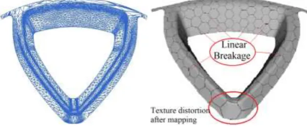
[image:1.595.140.455.549.679.2]Figure 1 shows a STL model of 3D surface of mold cavity of a part, in which the defects of triangular mesh distortion, void, loss, degeneration exits and too much narrow and flat triangular mesh can be found, so that the linear breakage and distortion of mapped 3D texture on the cavity surface can be found after mapping a 2D hexagon texture on the cavity surface (as shown in Figure 2). Therefore, it is always asked by users to optimize the STL model prior to the texture mapping process.
Figure 1. STL mold with defects. Figure 2. Texture defects after mapping.
The Characteristics of Optimization of 3D STL Triangular Mesh Model
(1) Handle large scale of triangular mesh model rapidly and effectively; (2) Build high quality of new triangular mesh model simply and easily;
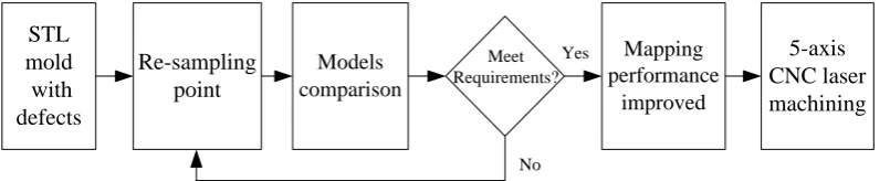
(3) Deal with any popular mesh robustly and keep its original feature even if it contains a lot of degenerated meshes. STL mold optimization flow is adopted as shown in Figure 3.
STL mold with defects
Re-sampling point
Models comparison
Mapping performance
improved
5-axis CNC laser machining Meet
Requirements?
[image:2.595.99.502.140.222.2]No Yes
Figure 3. STL mold optimization flow diagram.
The developed optimization methods of triangular mesh model theoretically rely on delaunay triangular parameterization technology[1-4], in which there are two major problems: first, it can easily make numerical instability when the quality of input triangular mesh is poor, since the calculation of parameterization extremely relies on mesh quality; second, it over relies on the uniform Euclidean measure between the vertices of the mesh, the mesh result is difficult to be adaptive, that is, it cannot be properly re-sampled in the complex geometry and prominent features.
At present, the research and application of 3D printing technology is in the ascendant, many references [5-7] have introduced the optimization method of STL model for 3D printing, but mainly focus on STL solid model instead of face model which texture map needs for laser machining.
Mesh Re-sampling
Re-sampling is one of the key steps of STL model optimization. To keep the feature of original STL model, re-sampling is to fast sprinkle points on original mesh, and make points distribution meets the requirements of model optimization. At first, the re-sampling algorithm is designed to capture the number of re-sampling points on the triangular patches and the model feature lines according to the number of vertices specified by the user, then, the triangular patches and the feature lines are re-sampled on the original mesh. The re-sampling process of optimization of STL model presented in the paper mainly involves three steps: re-sampling point calculation, triangular patch re-sampling and mesh vertex deletion.
Re-sampling Point Calculation
If ds and df are the density functions of calculation of the triangular patches and the feature lines respectively, both functions reflect the distribution of sampling points on triangular patches and the feature lines respectively. Define Rs and Rf as the sampling rate of the triangular
patches and the feature lines, that is, the sampling points on unit triangular patches and the feature lines. Sampling is isotropic, the triangle after sampling should be equilateral triangle[8].
2
1/ 2 s
A s
N R
S R
(1)
WhereNis the number of each triangle per unit area, SA is equilateral triangle area, a is
equilateral triangle side length. According to its feature, the relationship betweenRsandRfis below:
2 f
2 3
s R R
n feature
f f surface
s s
n R d uv dudv R d udu C
V
( , )
( ) (3) Where Vn is vertex points of output model that user expects, Cn is angle point number of model, it is the vertex that connects one or more than two feature edges in the model. When users give the vertex point number V of output model, the re-sampling point Rs on triangular patches
and re-sampling point Rf on feature lines can be calculated.
Re-sampling of Triangular Patches
In order to generate uniform stochastic barycentric coordinates, two random numerical value t1 and t2 uniformly distributed in the [0,1] interval are introduced, then t1 and t2 are sorted, let x1=min( t1, t2), x2=max(t1, t2), the expected value of x1and x2can be deducted as 1/3 and 2/3 respectively.
Therefore, the barycentric coordinates of three intervals, consisting of (0,x1), (x1, x2),(x2,1), are
uniformly distributed. When a random barycentric coordinate is obtained, the point can be inserted into the triangular patch, so that a better quality mesh is formed.
When re-sampling a triangular patch, it is assumed that the initial mesh M is the current triangle T.
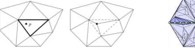
After obtaining a random barycentric coordinates (about sampling triangular T), at first it should be determined which triangle t the barycentric coordinates belong to among mesh M, then the point is inserted into the triangle t, the triangle is divided into three division, then delete original triangle t
as shown in Figure 4. Furthermore, the mesh M is triangulated by edge flipping to improve the mesh quality by Delaunay triangulation. Finally, repeat the above process until the number of re-sampling points equal to ST, the number of re-sampling points required for the current triangle T. During the re-sampling process of triangle patches, only a triangle will be divided into three divisions and processed to edge flip topological operations, so the process of mesh re-sampling can maintain numerical stability, would not impact the sampling quality due to poor mesh quality.
[image:3.595.107.437.441.522.2]
Figure 4. Original triangle divided into three. Figure 5. Edge split topology operation.
Re-sampling of Feature Line
Different from random sampling in the triangle on patches, re-sample the feature line through the accurate calculation of each position of the sampling points, in a feature line, each sampling points is related with sampling rate Rf. Through the calculation of sampling point, the sampling rate Rf
(sprinkling points on unit density) is easily obtained. It is needed to calculate Rf1 (the density of
sampling one point, in the case of even sampling, that is, the lengths between two adjacent points). Each feature line needs to be traversed in sequence, and a point needs to be sampled when the accumulated length is equal to the integer multiple of Rf1. When sampling in a feature line whose
length is l, the position of the sampling point x2[0,1] can be calculated as below,
2 1
1 ( )
x
f f
L x
D
d x dx R (4) Wherex1 is the known position of sampling, df(x) is the density function of feature line, DL
distribution, that is line length). After calculating the new position of x2, replace x1 to x2, and repeat
above process until the sampling points are equal to the required points of feature line.
Because the sampling point is at the edge of the feature line, the sampling point can be added to the mesh which finished patches sampling as shown in Figure 5, and it is assumed that the feature line could be kept well during the re-sampling process if triangular mesh edge split is a type of topology operation, so the numerical value can keep stable during the re-sampling process and would not impact sampling result even if poor mesh quality exists.
Mesh Vertex Delete
After re-sampling of input model, a hybrid mesh model which contains both initial model points and sampling points is obtained, and then the mixed mesh model is edge flipped by Delaunay triangulation, so as to improve the quality of hybrid grid as conducive to the subsequent algorithm operation.
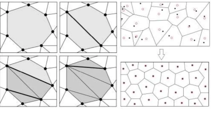
The model of fixed-point requirements should be satisfied, so the vertex points of the hybrid model are deleted, and new formed vertex points are the sampling points, those are vertex points required by user. The mesh obtained after deleting the initial vertex points will re-positioned by the Lloyd relaxation algorithm [8-9], a robust and efficient vertex deletion algorithm is adopted as shown in Figure 6, the idea of this algorithm is that when deleting a vertex points in the mesh, the vertex and adjacent triangles will be deleted, and a hole on the mesh is caused. The next step is to complete the hole and ensure the correct mesh topology as following:
[image:4.595.113.483.427.626.2]The first step of vertex points delete algorithm is vertex point classification, as shown in Figure 7.According to the topological properties of popular mesh, a mesh can be divided into the following two categories: one is simple vertex, that is a triangle’s circle and homeomorphism adjacent to the vertex; another is the boundary vertex point, that is a triangle’s half circle and homeomorphism adjacent to the vertex and is positioned in the mesh boundary.
Figure 6. Vertex points delete by robustness. Figure 7. Vertex points classification.
According to the connectivity of feature line, the simple vertex can be divided into ordinary feature points and angle points. Ordinary feature points are threshold linking feature points of two feature lines, and the angle between two feature lines is less than the given of valve α; angle points are connecting feature points of more than two feature lines, the angle between two lines are bigger than the given valve α.
Experiment and Conclusion
requirements, a better mesh is obtained by sprinkling points on original mesh, thus, the Lloyd relaxation method can converge rapidly in the iterative process. In the process of re-meshing, the algorithm can guarantee the accurate description of the input mesh because it always records the correspondence between the points on the new mesh and the points on the input mesh for laser marking of 3D surface.
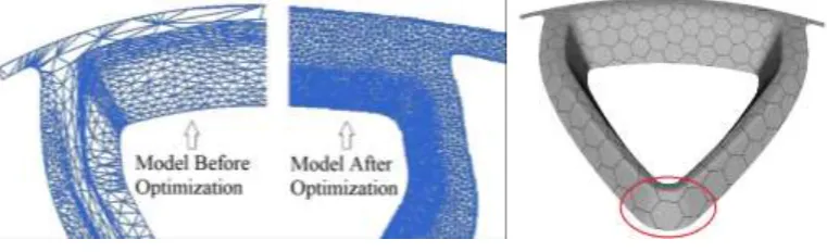
Figure 8. Models comparison. Figure 9. Mapping performance improved.
Figure 8 is the re-meshing model after optimizing original model as shown in Figure 1 by the algorithm, it can be found that based on keeping the feature of original model, the optimized model has removed most of defects and has been used for texture mapping to obtain better result as shown in Figure 9 in which the linear breakage defect does not exist and the performance of decrease of texture distortion gets improved.
Acknowledgements
This work was financially supported by Guangdong Science and Technology Plan (2015A050502006) in China, Shenzhen Science and Technology Plan (GJHZ20150316112419786, JCYJ20150417094158016 and GJHZ201602291617491275), Guangdong higher education excellent youth teacher training Plan (YQ2014124) in China.
References
[1] Jean-Daniel Boissonnat, Kan-Le Shi, Jane Tournois and Mariette Yvinec. Anisotropic Delaunay meshes of surfaces, ACM Trans.Graph, 266(2014) 102-112.
[2] Zichun Zhong, Xiaohu Guo, Bruno Levy. Particle-based anisotropic surface meshing, ACM Trans. Graph. (SIGGRAPH) 32, 4(2013)99:1-99:14.
[3] Information on http://en.wikipedia.org/wiki/Delaunay_triangulation.
[4] Leonidas J. Guibas, Donald E. Knuth, Micha Sharir. Randomized incremental construction of Delaunay and Voronoidiagrams, Algorithmica 7, 1-6 (June), 381-413,1992.
[5] Jean-Marie Mirebeau. Optimal meshes for finite elements of arbitrary order, Constructive approximation 32, 2, 339-383, 2010.
[6] William Oropallo, Les A Piegl. Ten challenges in 3D printing, Engineering with Computers, 135-148, 32(1), 2016.
[7] Yan Fu, Bing-Feng Zhou. Direct sampling on surfaces for high quality remeshing, CAGD 26, 711–723, 2009.
[8] XU Bin, LI Zhong-ke, Laplacian Mesh Optimization Algorithm Based on STL File, Computer Engineering (In China), 2013, 39(11): 245-248.
[9] Xinxin Shen. Two-Manifold Triangular Mesh Re-meshing. A Dissertation Submitted to Zhejiang University for the Degree of Master of Engineering. 2015. (In Chinese)