Systems Reference Library
IBM 1
BOO Operating Procedures
This publication is a guide for operators using the
mM
1800 System console and data processing input/output
devices.
Itcovers
indetail operator duties normally
encountered when using the system console or operating
the data processing input/output devices. No specific
programming system is assumed.
Functions of the system console keys, lights, and
switches are included
inthis publication, as well as
descriptions of the operator keys and lights, manual
controls, setup procedures, and principles of operation
for the data processing input/output devices. Procedures
for clearing conditions that require operator intervention
are given.
Preface
This publication is intended for use as a guide for operators using the data processing (DP) input/output (I/O) devices attached to the IBM 1800 System. It is for operators who have had only a minimum amount of training on stored-program computer systems. This publication covers in de-tail the usual duties of an operator in conjunction with the DP I/O devices and the IBM 1800 System.
The practices and techniques given are approved methods based on the preference of IBM and the practices of many experienced operators. The user must remember, however, that the employer has the prerogative of determining the operator's procedures and responsibilities.
This publication contains a section on the processor-controller and each DP I/O device. Each section is designed as a stand-alone unit containing the pertinent operator information necessary for each device. Pictorial illustrations are included for their value in clarifying procedures.
Second Edition (January 1970)
This is a major revision of and makes obsolete, GA26-S7S3-0 and Technical Newsletter GN26-0237. The format of this manual has been changed and the entire manual has been rewritten. No major technical changes have been made.
Manuals referred to in this publication that have a form number with a four digit prefix are identical in content to the same manual without the initial prefix character. (e.g. GA26-xxxx is the same in content as A26-xxxx.)
The illustrations in this manual have a code number in the lower corner. This is a pub-lishing controi number and is not reiated to the subject matter.
Copies of this and other IBM publications can be obtained through IBM Branch Offices.
A form is provided at the back of this publication for your comments.
This manual was prepared by the IBM Systems Development Division, Product Publica-tions, Department G24, San Jose, California 95114.
© Copyright International Business Machines Corporation 1968
ii
Contents
THE ROLE OF THE OPERATOR Clearing a Parity Check Condition 49
THE PROGRAM AND RUN BOOK Clearing a Forms Check Condition 49
OPERA TOR RESPONSIBILITIES
IBM 1627 PLOTTER 52
INTRODUCTION 2 Operator Controls, Left Panel . 52
Input/Output Control 2 Operator Controls, Right Panel 53
DATA CHANNEL CONTROL 2 Installing a Roll of Graph Paper 53
DIRECT PROGRAM CONTROL . 3 Installing a Sheet of Graph Paper 54
INPUT/OUTPUT INTERRUPTS. 3 Assembling the Pen . 55
Checking Plotter Operation 55
IBM 1801/1802 PROCESSOR-CONTROLLER . 6 Program Checkout Routine 56
Processor-C on troller Console 6
Pushbutton Switches and Lights, Top Row 8 IBM 1816 PRINTER-KEYBOARD AND IBM 1053 PRINTER 58
Pushbutton Switches, Bottom Row 9 PRINTER 58
Rotary Switches 10 KEYBOARD 58
Toggle Switches 11 Operator Controls, Keyboard 58
Status Indicators 11 Operator Controls, 1053 Printer 59
Data Flow Indicators 12 Manual Controls, Printer 60
Main Storage Display (Single Instruction Operations) 13 Print Element and Ribbon Controls
-
61Main Storage Display (Single Cycle Operations) . 13 Inserting Forms . 61
Main Storage Load 13 Changing the Ribbon 62
Changing the Print Element 63
IBM 1054 PAPER TAPE READER 16 Setting Margins . 64
PAPER TAPE INITIAL PROGRAM LOAD . 16 Clearing a Not Ready Condition 64
Operator Controls 16 Clearing an Overprint Condition 64
Identifying Start of Tape 17 Clearing Double Key Errors 64
Loading Punched Tape . 17 Example of Keyboard Operation 64
Loading a Tape Loop 18
IBM 1810 DISK STORAGE 66
Splicing Paper Tape. 19
Operator Controls 66
Clearing Error Conditions 19
Removing a Disk Cartridge. 67
IBM 1055 PAPER TAPE PUNCH. 22 Inserting a Disk Cartridge 68
Operator Controls 22 Clearing a Write Select Error Condition 68
Loading Blank Tape 23 Disk Cartridge Handling 68
Removing Punched Tape 24 IBM 2841 STORAGE CONTROL AND 2311 DISK
Emptying the Chad Box 24 STORAGE DRIVE . 70
Clearing a Not Ready Condition 25 2841 STORAGE CONTROL 70
2311 DISK STORAGE DRIVE 70
IBM 1442 CARD READ PUNCH. 28 Operator Controls, 2841 70
CARD READING 28 Operator Controls, 2311 71
CARD PUNCHING . 28 Removing a Disk Pack 72
CARD FEED. 28 Loading a Disk Pack 73
INITIAL PROGRAM LOAD 28 Disk Pack Handling. 74
Operator Controls 29
Readying the 1442 . 30 IBM 2401 MAGNETIC TAPE UNIT 76
Initiating Last Card Sequence 30 WRITING AND READING MAGNETIC TAPE. 76
Clearing Card Jams . 31 FILE PROTECTION DEVICE 76
Clearing Error Conditions 32 Operator Controls 77
Operating the Power Window 78
IBM 1443 PRINTER 38 Loading Magnetic Tape. 79
CARRIAGE. 38 Unloading Magnetic Tape 80
Operator Controls 39 Placing Tape Markers on Magnetic Tape 80
Manual Controls, Left Side 40 Cleaning the Tape Transport 81
Manual Controls, Front 41 Magnetic Tape Handling 82
Manual Controls, Right Side 42
APPENDIX A. CARRIAGE CONTROL TAPE 83
Inserting a Control Tape 42
Inserting Forms . 43 Marking a Tape for Punching (Six Lines Per Inch) 84
List of Illustrations
Figure Figure
I
1 Processor-Controller Console 7 17 1627 Pen and Paper Motions 52
2 Console Pushbutton Switches and Lights, 18 1627 Switches, Left Panel .. 52
Top Row. 8 19 1627 Switches, Right Panel 53
3 Console Pushbutton Switches and Lights, 20 1816 Keyboard Keys and Lights 59
Bottom Row. 9 21 1053 Printer Keys 60
4 Console Rotary Switches 10 22 Printer Manual Controls 60
5 Console Toggle Switches 11 23 Print Element and Ribbon Controls 61
6 Status Indicators 11 24 2315 Disk Cartridge. 66
7 Data Flow Indicators 12 25 1810 Keys and Lights 66
8 1054 Operator Controls 16 26 1316 Disk Pack . 70
9 1055 Operator Controls 22 27 2841 Switch . 71
10 1442 Card Path . 28 28 2311 Switches and Lights 71
11 1442 Keys and Lights 29 29 2401 Tape Feed Path 76
12 1443 Printing Schematic 38 30 File Protection Ring 76
13 1443 Keys, Switches, and Lights 39 31 2401 Keys and Lights 77
14 1443 Manual Controls, Left Side 40 32 2401 Tape Transport Models 2 or 3 81
15 1443 Manual Controls, Front 41 33 2401 Tape Transport Modell. 82
16 1443 Manual Controls, Front . 42 A-I Carriage Control Tape 83
The IBM 1800 Data Acquisition and Control System was developed to meet the needs for real-time data acquisition, analysis, and control. Real-time applications normally require continuous on-line communication between the system and
some process or operation occuring outside the computer system. These real-time applications, with continuous operation, require little operator intervention once started.
In many installations, however, the real-time control system does not utilize all the computer time. Through time-sharing, idle computer time can be used to perform background jobs such as data processing or scientific com-putations. It is in this area that the operator exhibits his abilities.
In most installations, the tasks of the operator are divorced from those of the programmer, system analyst, and keypunch operator. In some installations, however, one individual performs more than one of these tasks. The subjects treated in this manual will help the operator learn to operate the data processing input/output devices and processor-controller console used in an 1800 system instal-lation.
In most cases, the operator works directly with the machine. In data processing applications, he must under stand that he cannot allow the machine to remain idle. The operator should not attempt to supply data which should have been provided by the programmer. In such cases, the operator should terminate the job and return it to the programmer for correction. This action minimizes or eliminates idle computer time.
The Program and Run Book
The system analyst initiates the first steps in developing a program. He analyzes the information supplied by the user, decides upon the most efficient means of instructing the computer to process the information, and divides the problem into segments. Each pr~blem segment is then solved by the programmer, who lists the specific steps required to instruct the computer to solve that segment. The programmer writes the instructions for the computer in a special programming language. This list of instructions is called a program.
The program is then punched into IBM cards (called a source program deck) by keypunch operators. The
com-The Role of the Operator
puter cannot execute a source program because a source program is in a programming language and not in machine language. The source deck is then translated during a com· puter run by a program called an assembler or a compiler, which produces an object program in machine language. For simplicity, we will refer to the executable program as the "program." An executable program may be in cards as a program deck, or it may be on a disk.
The programmer also supplies a series of instructions and notes (called a run book), which gives the operator specific information regarding the particular program. The program deck and the run book are delivered to the opera tor, who depends on the run book to tell him what he must know to proceed with the processing operation. For example, the programmer includes error messages in his program to describe errors that would occur because of incorrect input data or an incorrect operational procedure. The operator refers to the run book to determine what corrective action to take when an error occurs. The run book also tells him which program deck or disk to use, which forms to use in the printer, and how to continue with the processing when departures from conven tional procedures are necessary.
To this extent the operator works with the programmer.
the
run book, which has been prepared by the programmer for each specific program, is used by the operator as one of his tools while running the program through the computer. The operator uses the program and the machine to complete the processing of data. He does not explore all of the factors that determine the structure of the program.Operator Responsibilities
Introduction
The IBM 1800 Data Acquisition and Control System handles a wide variety of real-time applications such as process control and data acquisition. Each system is individually tailored with modular building blocks that are easily integrated to meet specific system requirements.
Components of the 1800 system are functionally sep-arated into·four categories: Processor~ontroller, data processing input/output (DP I/O), communications input/output, and process input/output. Processor-controller is the name given to the computer subsys'-tern which includes the central processing unit (CPU), main storage, and I/O channel controls.
The 1800 system offers a wide variety of highly flexible input/output (I/O) devices:
IBM 1053 Printer
IBM 1054 Paper Tape Reader IBM 1055 Paper Tape Punch IBM 1442 Card Read Punch
IBM 1443 Printer IBM 1627 Plotter IBM 1810 Disk Storage IBM 1816 Printer-Keyboard
IBM 2311 Disk Storage Drive (via IBM 2841 Storage Control)
IBM 2401 Magnetic Tape Unit
This manual describes oniy the data processing ILO devices in the preceding list and the processor-controller (1801/1802).
In addition to these data processing I/O devices, the 1800 system offers communications devices such as 2790 Adapters, System 360 Adapter, and Communications Adapters as well as process I/O devices. These devices are described in IBM 1800 Functional Characten'stics,
Form GA26-5918. Operator information for 2790 com-ponents can be found in
IBM
2790 Data Communica-tions System Components Description, Form GA27-3015.INPUT/OUTPUT CONTROL
Data processing (DP) I/O operations involve the transfer of information to or from main storage and DP I/O devices. I/O device operation is regulated by a control (adapter) function. All DP I/O deVices, except the 1810 and 2311, require an adapter and/or controls in the processor-controller. The 1810 contains its own adapter(s). The 2311 operates via a 2841 Storage Controi which is in turn controlled by a selector channel located in an IBM 1826 Data Adapter Unit.
In all cases, the control function provides the logical and buffering capabilities necessary to operate the associated device.
The 1800 system uses two methods to control I/O devices:
Data channel control (cycle steal) Direct program control
2 IBM 1800 Operating Procedures
Data Channel Control
High-speed I/O devices, such as magnetic tape units and disk storage devices, must be able to control transmission of data to and from main storage on a cycle-steal basis. The complex of registers, data paths, and control required for this function is called a data channel.
Data channels give the processor-controller the ability to delay the execution of a program while an I/O device com-municates with main storage. For example, if an input device requires a main storage cycle to store data, the data channel with its cycle stealing capability makes it possible to delay the program during execution of an instruction and store the data word without changing the logical condition of the processor-controller. After the data is stored, the processor-controller continues executing the program which was delayed by the cycle stealing.
When several data channels require main storage cycles at the same time, the sequence of transmission is handled automatically according to priorities previously established by the user.
The following DP I/O devices are under data channel control:
IBM 1442 Card Read Punch IBM 1443 Printer
IBM 1810 Disk Storage
IBM 2311 Disk Storage Drive (via 2841 Storage Control and selector channel)
IBM 2401 Magnetic Tape Unit
Direct Program Control
Direct program control transfers individual words of data between processor-controller main storage and the I/O device at a rate controlled by the program and maximum speed of the I/O device. The processor-controller program is interrupted for each word transfer and must branch to a routine which services the I/O device. Therefore, the logical condition of the processor-controller is changed.
The following DP I/O devices are under direct program control:
IBM 1053 Printer
IBM 1054 Paper Tape Reader IBM 1055 Paper Tape Punch IBM 1627 Plotter
IBM 1816 Printer-Keyboard
Input/Output Interrupts
Interrupt is described as an automatic branch in the normal program sequence based upon an external condition.
Input/output interrupts are initiated by such conditions as:
1. Termination of an I/O operation by certain error conditions.
2. Completion of the programmed instruction. 3. Operator intervention at the I/O devices. 4. I/O unit operating under direct program control
requires service.
Input/output interrupts enable the processor-controller to provide appropriate programmed responses to conditions that occur in I/O devices.
I
This page left blank intentionally.
IBM 1801/1802 Processor Controller
The IBM 1801 and 1802 Processor-Controllers are stored program computers, composed of a central processing unit (CPU), main storage, and channel control circuits.
Either the 1801 or 1802 may be used in the 1800 sys-tem. The 1802 includes circuitry and control for connection and operation of the IBM 2401 Magnetic Tape Unit. The 1801 has no standard provisions for magnetic tape units. Each processor-controller is available with five main storage capacities: 4,096; 8,192; 16,384; 24,576; or 32,768 words. Total system main storage capacity can be expanded in 8,192 word increments to 65,536 words with the addi-tion of an IBM 1803 Core Storage Unit. In systems with main storage capacities above 32,768 words, 24,576 words are located in the processor-controller. The remaining main storage words are located in the 1803 Core Storage Unit.
Standard features of the processor-controller include three hardware index registers, 12 levels of priority interrupt (expandable to 24 by special feature), three data channels (expandable to 15 by special feature), three interval timers, an operations monitor, and an operator's console.
The processor-controller contains a binary stored-program CPU. Within its basic design, the CPU has interrupt and cycle-stealing capabilities which are used in controlling the various I/O devices to be attached to the using system. Index registers and indirect addressing are provided to facilitate address modification and programming.
A complete instruction set with powerful options gives the computer very high performance for tasks normally encountered in data acquisition and process control appli-cations.
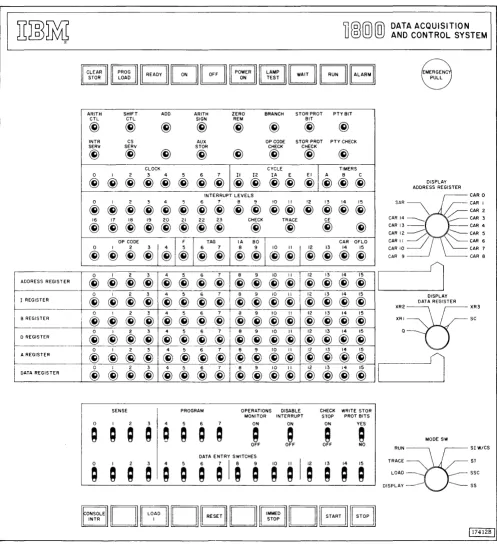
PROCESSOR-CONTROLLER CONSOLE
The processor-controller console (Figure 1) provides the means for manual control of the processor-controller during debugging or operation phases.
The basic operating features and controls provide the facility to:
1. Start or stop instruction execution. 2. Address main storage.
3. Set up and store data or instructions.
4. Communicate with the program via sense or program select switches.
5. Control the cycling rate in the run. single main storage
6 IBM 180e Operating Procedures
cycle, single instruction, or single step modes. 6. Interrupt the program manually.
7. Trace each instruction.
8. Reset all control circuitry and main storage. 9. Turn power on and off.
10. Indicate basic machine conditions and status. 11. Display main storage words and register data. 12. Write or clear storage protect bits.
13. Clear main storage.
14. Allow program execution with an internal error such as invalid operation, parity, or storage protect.
ADDRESS REGISTER
I REGISTER
8 REGISTER I
D REGISTER
A REGISTER
,
I
DATA REGISTER
ARITH CTL
@
INTR SERV@)
0@)
0@
16@)
0@)
0@
0@
0@
0@)
0@)
SHIFT ADD ARITH ZERO BRANCH STORPROT PTYBIT
CTL SIGN REM BIT
@
@)
@)
@
@)
@)
@)
CS AUX OP CODE STOR PROT PTY CHECK
SERV STOR CHECK CHECK
@)
@)
@
@)
@)
@)
@)
CLOCK
I
"'"
I
nM'" I 2 3 4 5 6@ @ @ @@
@@@@
@ @
@@
@ @)
INTERRUPT LEVELS
I 2 3 4 5 6 7 8 9 10 II 12 13 14 15
@ @) @ @ @ @ @ @ @
@@
@
@@@
17 18 19 20 21 22 23 CHECK TRACE CE
@ @) @ @ @) @) @
@
@
@
@
@"~'
@
I@I~
I@"'@ I
~ ~I
i
@
I
@
@
i
o~
I 2 3 4 5 6 7 8 9 10 II 12 13 14 15@)
@@
@@
@ @
@@ @@ @)@@@
I 2 3 4 5 6 7 8 9 10 II 12 13 14 15
@
@)
@
@)@
@) @)
@)@) @)@)
@)
@)@)@)
I 2 3 4 5 6 7 a 9 10 II 12 13 14 15
@) @
@
@)@)
@ @
@)@)@)@)
@@)@@)
I 2 3 4 5 6 7 8 9 10 II 12 13 14 15
@)
@@) @)
@@) @)
@)@ @)@)
@)
@)@)@)
I 2 3 4 5 6 7 8 9 10 II 12 13 14 15@)
~@) @)
@)i @) @) @)
@) @)
@)@)@)
DATA ACQUISITION AND CONTROL SYSTEM
EMERGENC PULL
DISPLAY ADDRESS REGISTER
'&
CARO SAR ~r--
CAR I\ /~CAR2
CAR 14 _____ ~ CAR 3 CAR 13 - - - - CAR 4 CAR 12 --- ~ CAR 5
"'"
CARIO~~// \\~'~'
~CAR 7CAR 9 CAR 8
1
DISPLAY DATA REGISTER
::;=r!f:;'
,----11
@)@)@~I@~@@I@@@@I@@@@II
@)I~
I
A A
-
-
.-
...-SENSE PROGRAM OPERATIONS DISABLE CHECK WRITE STOR MONITOR INTERRUPT STOP PROT BITS o I 2 3 4 5 6 7 ON ON ON YES
Q ; ; ;
; Q Q
~
~
~
A
~
MODE SWOFF OFF OFF NO
RUN~SIW/CS
TRACE~ SJ
LOAD _____ SSC
DIS P LAY --- --- S S
DrEJDBD
DBB
[image:11.613.68.565.68.611.2]r - I l t ' I J n l l T T A I \ I t'InI!TI"'LJr"t' I \ I \ I n I I r " ' L J T t ' T A n n A I r " Ir:-:: .•.. _.-.
'l'
r-V~IIUV I I VIV ~VVI I "'IlL.." J-\IVLJ L . . I U I I I " , I VI I l V V V \I I~UIC "-I
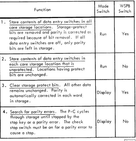
The Clear STaR (Stu rage) Switch has four functions as shown in Table 1. These four functions are enabled by first holding CLEAR STOR down and then pressing START. This dual action requirement prevellts accidental clearing of main storage. Note in Table 1 that each clear storage function is dependent on the positions of two console switches: the mode switch and write storage protect bits switch.
The processor-controller cycles completely through all main storage addresses during execution of each clear storage function.
The PROG (Program) Load Switch is used to load the first 1442 card or 1054 tape record into main storage. This first card or tape record must contain instructions that initiate the loading of the remaining cards or tape records. (The processor-controller must be in run mode for p,rogram operation.) Only one input device can be used for initial program load (IPL) and it must be in ready status. The first
1442 on the system is used for IPL. The 1054 is used for IPL if there is no 1442 on the system.
The first card or tape record is read into main storage beginning at the location specified by the I-register. Normally, RESET is pressed prior to pressing PROG LOAD. This resets the I-register to 0000. After RESET is pressed, the I-register may be manually altered to some address other than 0000. This allows the first card or tape record to be placed at any location in main storage.
In any case, the processor-controller branches to location 0000 to begin instruction execution after the first card or tape record has been transferred to main storage. Therefore, location 0000 should contain a valid instruction.
The Ready Light being on indicates that the processor-controller is in an operative condition.
The Power On Switch is used to turn on the power supplies within the processor-controHer.
Mode WSPB Function Switch Switch
1. Store contents of data entry switches in all core storage locations. Storage-protect
bits are removed and parity is corrected as Run Yes required because of bit removal. If all
data entry switches are off, only parity bits are left in storage.
2. Store contents of data entry switches in each core storage location that is
Run No unprotected. Locations having protect
bits are unchanged.
3. Clear storage protect bits. All other data
remains unchanged. Parity is Display Yes automatically corrected in each word:
in storage.
4. Search for par i ty errors. The P-C cycles through storage until stopped by the
stop key or a parity error. The check Display No stop switch must be on for a parity error to
cause a stop.
Table 1. Clear Storage Functions
The Puwer Off Switch is used to turn off the power supplies within the processor-controller.
The Power On Light being on indicates that the processor-controller power supplies are operative.
The Lamp Test Switch applies lamp voltage to all console lamps when it is pressed. It is used to verify operation of all console lamps.
The Wait Light being on indicates that the processor-controiler is in the stopped or wait state. The Slopped or
POOWNER 1111 LAMP
I I
4 F- 4 F===j
: 1 . - . _T_EST-..JI
L;;J
I RUN I I ALARMI
Figure 2. Console Pushbutton Switches and Lights, Top Row
8 IBM 1800 Operating Procedures
[image:12.613.304.539.127.370.2] [image:12.613.39.544.615.688.2]wait state occurs when:
1. The processor-controller is in load or display mode. 2. The processor-controller has been halted by a wait
instruction from the program.
3. STOP or IMMED STOP has been pressed.
The Run Light being on indicates that the processor-controller is operating under program control.
The Alarm Light being on indicates that the operations monitor has timed out. The alarm light remains on until
the operations monitor switch is turned off. The customer may install an audible alarm to operate in conjunction with the alarm light.
Emergency Pull Switch is for emergency use only. If pulled out, all electrical power within the processor-controller is turned off, including power to the blowers that cool the electronic circuitry. Repeatedly turning the blowers off in this manner may damage some of the circuitry. Therefore, use this switch only in emergencies. The switch must be reset by a customer engineer.
PUSHBUTTON SWITCHES, BOTTOM ROW (Figure 3)
The Console Interrupt Switch enables the operator to signal the program by causing an interrupt. Normally, the
program and sense switches are used in conjunction with console interrupt to allow operator communication to the program.
The Load I (Instruction) Switch is used with the mode switch positioned at LOAD to transfer the contents of the data entry switches into the I-register. The processor-controller is in the stopped condition when it terminates the load I operation.
The Reset Switch is used to reset all I/O devices, basic timing controls, and registers (except index registers and address registers). Digital input and digital-analog output registers are not reset. RESET is effective only when the processor-controller is not in a run state as indicated by the run light being off.
The IMMED (Immediate) Stop Switch stops the processor-controller at the end of the main-storage cycle in progress
when the switch contacts close. All I/O devices, basic timing controls, and registers (except index registers and address registers) are reset. IMMED STOP also stops data channel (cycle steal) operations which can cause loss of information due to premature termination of a data transfer operation.
The Start Switch initiates processor-controller operation as specified by the mode switch. The processor-controller must be ready as indicated by the ready light being on.
The Stop Switch stops the processor-controller at the end of the main-storage cycle in progress when the switch contacts close. The processor-controller registers and 1/0 devices are not reset and data channel (cycle steal) operations will continue until completed.
If an interrupt occurs on an interrupt level with higher priority than any in progress at the same time STOP is pressed, STOP must be pressed again to be effective. Once the processor-controller has been stopped, pressing START causes the program to resume operation.
CONSOLE
Dc:EJDGDI
IMMEDIDGB
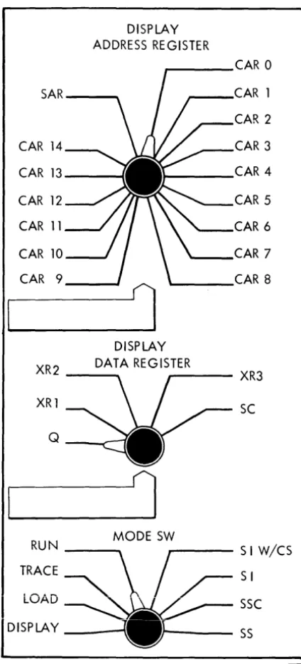
ROTARY SWITCHES (Figure 4)
The Display Address Register Switch is used to select a channel address register or storage address register for display in the address register lights.
DISPLAY ADDRESS REGISTER
CAR 0
SAR CAR 1
CAR 2
CAR 14 CAR 3
CAR 13 CAR 4
CAR 12 CAR 5
CAR 11 CAR 6
CAR 10 CAR 7
CAR 9 CAR 8
DISPLAY
XR2 DATA REGISTER XR3
XR1 SC
Q
1
RUN MODE SW S I W/CS
TRACE SI
LOAD SSC
I
DISPLAY SS[17676c!
Figure 4. Console Rotary Switches
10 IBM 1800 Operating Procedures
The Display Data Register Switch is used to select the Q-register (which is the A-register exteIlsiun), and index register, or the shift counter for display in the data register lights.
The fir/ode SU' (Switch) is used in conjunction with START
I
to extend operator control of the processor-controller. Thefunction of each position of the mode switch is described in the following paragraphs.
DISPLAY is used to display the contents of main storage. Pressing START with the mode switch on DISPLAY causes the data at the address specified by the I-register to be displayed in the B-register lights. The I-register is incremented after each display. Pressing START successively displays the data in ascending main storage locations.
LOAD is used to load main storage locations or the I-register. Pressing START with the mode switch on LOAD causes the contents of the data entry switches to be stored at the address specified by the I-register. (The processor-controller must be in a stopped condition.) The I-register is incremented following each load operation. Pressing START successively loads the contents of the data entry switches into ascending main storage locations.
Pressing LOAD I with the mode switch on LOAD causes the contents of the data entry switches to be stored in the I -register.
TRACE is used to initiate an interrupt on the lowest priority level after the execution of each instruction (except execute I/O instructions). This position of the mode switch is usually used for program debugging.
RUN is used for normal program operation. Pressing START with the mode switch on RUN initiates program operation of the processor-controller.
SI W /CS (Single Instruction With Cycle Steal) allows execution of one instruction each time START is pressed. Data channel (cycle steal) operations can occur during execution of the instruction.
SI (Single Instruction) allows execution of one instruction each time START is pressed. Data channel (cycle steal) operations are preventede
SSC (Single Storage Cycle) allows one main storage cycle each time START is pressed. Single storage cycle operations (usually called single cycle operations) can be used in conjunction with the cycle lights to step through instructions and anaiyze processor-controller operation.
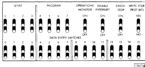
[image:14.620.46.258.159.626.2]TOGGLE SWITCHES (Figure 5)
The Sense and Program Switches are normally used for communication with the program. The contents of these eight switches may be stored in bit positions 0 through 7 of the A-register or a main storage location as directed by the stored program.
The Operations Monitor Switch, when on, enables the operations monitor. The off position disables the opera-tions monitor.
The Disable Interrupt Switch is used to mask or disable all interrupt levels. It is used to choose the time at which the program may be interrupted during program analysis.
SENSE PROGRAM OPERATIONS DISABLE CHECK WRITE STOR MONITOR INTERRUPT STOP PROT BITS
0 ON ON ON YES
~ ~ ~ ~
~ ~
;
;
~
;
~ ~
OFF Off OFF NO DATA ENTRY SWITCHES
3 5 6 7 8 10 II 12 13 14 15
;
~ ~ ~
~ ~ ~ ~
~ ~ ~ ~ ~ ~ ~ ~
Figure 5. Console Toggle Switches
The highest priority level on and unmasked (not disabled) is serviced when the switch is turned off.
The Check Stop Switch is used to stop processor-controller operation when one of the following conditions occurs: operation code check, storage protect check, or parity check. The stop occurs at the end of the main-storage cycle in which the check is detected. The appropriate error light will be on. START must be pressed to restart the system.
The preceding check conditions initiate an internal (check) interrupt if the check stop switch is off.
A clear storage function is stopped when the check stop switch is on and a parity check is detected.
The Write STaR PROT (Storage Protect) Bits Switch enables the writing or clearing of storage protect bits when the switch is on. A parity error may occur if the position of this switch is changed while the processor-controller is running.
The Data Entry Switches provide a means of entering data under either manual or program control. Under program control, the contents of the switches can be stored in main storage or the A-register. Under manual control, the contents of the switches can be stored at the address specified by the I-register by pressing START, or loaded into the I-register by pressing LOAD I provided the mode switch is on LOAD.
STATUS INDICATORS (Figure 6)
ARITH SHIFT ADD ARITH ZERO BRANCH STOR PROT PTY BIT
ClL ClL SIGN REM BIT
~ ~ ~ ~ ~ ~ ~ ~
INTR CS AUX OP CODE STOR PROT PTY CHECK SERV SERV STOR CHECK CHECK
~ ~ ~ ~ ~ ~ ~ ~
CLOCK CYCLE TIMERS
0 I 2 3 4 5 6 7 II 12 IA E EI A B C ~ ~ ~ ~ ~ ~ ~ ~ ~ ~ ~ ~ ~ ~ ~ ~
INTERRUPT LEVELS
0 I 2 3 4 5 6 7 8 9 10 II 12 13 14 15 ~ ~ ~ ~ ~ ~ ~ ~ ~ ~ ~ ~ ~ ~ ~ ~
16 17 18 19 20 21 22 23 CHECK TRACE CE
~ ~ ~ ~ ~ ~ ~ ~ ~ ~ ~ ~
OP CODE F TAG IA 80 CAR OHO 0 I 2
~I~
5 6 7 8 9 10 II 12 13 14 15~ ~ ~ ~ ~ ~ ~ ~ ~ ~I~ ~ ~ ~
The ARITH CTL (Arithmetic Control) Indicator turns on during arithmetic operations.
The Shift CTL (Control) Indicator turns on during shift operations.
The Add Indicator is on during add operations.
The ARITH SIGN (Arithmetic Sign) Indicator turns on when bit position 0 in the A-register does not initially equal bit position 0 in the B-register.
The Zero REM (Remainder) Indicator is on when the A-register contains a 0 balance during a divide instruction.
The Branch Indicator is on during branch instructions. The STaR PROT (Storage Protect) Bit Indicator is on when a storage protect bit is transferred with the 16 data bits between the B-register and main storage.
[image:15.617.62.308.286.401.2]The INTR SER V (Interrupt Service) Indicator turns on when a hardware forced branch instruction IS being executed to enable service of the highest priority interrupt level that is on.
The CS SER V (Cycle Steal Service) Indicator is on during cycle steal operations of a data channel.
The AUX STOR (CE Storage) Indicator is on when CE storage is being used. CE storage is provided for Customer Engineering use.
The OP (Operation) Code Check Indicator turns on when an invalid operation code is detected in the OP reEister. This indicator is turned off and the check indicator is turned on when the next main storage cycle is initiated. This allows the OP code check indicator to indicate any subsequent error.
The STOR PROT (Storage Protect) Check Indicator is turned on when an attempt is made to write into a read-only location of main storage. This indicator is turned off and the check indicator is turned on when the next main storage cycle is initiated. This allows the STOR PROT check indicator to indicate any subsequent error.
The PTY (Parity) Check Indicator is turned on when a parity check (even number of bits on) is detected in the 18-bit word transfer between the B-register and main storage. This indicator is turned off and the check indicator is turned on when the next main storage cycle is initiated. This allows the PTY check indicator to indicate any subsequent error.
The Clock Indicators (0 through 7) show the advance of the basic processor-controller clock during single step opera-tions.
The Cycle Indicators (I I . 12, E, and E I ) show the progress of an instruction during single step or single cycle operations.
The Timers Indicators (A, B, and C) show the status of their respective interval timers. An on condition indicates that the timer is in operation.
The Internlpt Levels Indicators (0 through 23, check, trace, and CE) show the status of their respective interrupt levels. The indicator being on indicates that the level is requesting service.
The OP (Operation) Code Indicators (0 through 4) display the operation code of each instruction.
The F (Format) Indicator is on when a two-word instruction is being executed.
The Tag Indicators reflect the index registers used in modi-fication of the address portion of an instruction.
The IA (Indirect Addressing) Indicator (bit 8) is on when bit 8 of the instruction is also on. This bit only indicates indirect addressing if the F-bit is on.
The BO (Branch Out) Indicator is on when there is a bit in position 9 of an instruction.
The Carry and Overflow Indicators are turned on individ-ually when their respective conditions occur in the A-register.
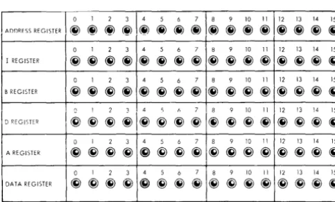
DATA FLOW INDICATORS (Figure 7)
The Address Register Indicators display the data in the register selected by the display address register switch. The selected register is displayed each time the processor-controller comes to a stop or wait condition.
The I (Instruction) Register Indicators display the contents
-
- - --0 I 2 3 4 5 6 7 8 9 10 II 12 13 14 15
I REGISTE,~ ~~~~ ~~~~ ~~~~ ~~~ ~ 0 I 2 3 4 5 6 7 8 9 10 II 12 13 14 15
B REGISTER ~~~~ ~~~~ ~~~~ ~~~~
(\ 1 ? 1 .4 C; f, 7 8 9 10 II 12 13 14 15
D REGISTER
~~~~I~~~~
~~~~ ~~~~0 I 2 3 4 5 6 7 8 9 10 II 12 13 14 15
A REGISTER ~~~~ ~~~~ ~~~~ ~~~~
I
I
DATA REGISTERo I 2 3
I
4 5 6 7I
8 9 10 III
12 "i3 14 i5I
~ @ ~ ~I~ ~ ~ ~I~ @) ~ ~I~ ~ ~ ~lFigure 7. Data Flow Indicators
12 IBM 1800 Operating Procedures
of the I-register. The I-register holds the address of the next sequential instruction and is automatically incremented for sequential instruction operation.
The B (Storage Buffer) Register Indicators display the contents of the B-register. The B-register is used to buffer all word transfers with main storage.
The D (Arithmetic Factor) Register Indicators display the contents of the D-register. The D-register is used to hold one operand of any arithmetic or logical operation. The A-regIster provides the other operand.
The A (Accumulator) Register Indicators display the contents of the A-register. The A-register contains the results of any arithmetic and logical operation. It can be loaded from or stored into main storage,.shifted right or left, and otherwise manipulated by specific arithmetic and logical instructions.
TIle Data Register Indicators display the contents of the
register selected by the display data register switch. The selected register is displayed each time the processor-controller comes to a stop or wait condition.
[image:16.620.37.279.570.716.2]MAIN STORAGE DISPLAY (Single Instruction Operations)
The following procedure may be 'lsed to display main storage data between execution of single instructions. The processor-controller must be in a stopped condition before starting this procedure.
1. Position the mode switch to SI.
2. Press START repeatedly to step program to point at which data display is desired.
3. Record address in I-register. This address is needed to return to next instruction in program.
4. Enter address of main storage location to be displayed in data entry switches.
5. Position mode switch to LOAD. 6. Press LOAD I.
7. Position mode switch to DISPLAY.
8. Press START. The selected data is now displayed in B-register indicators.
9. To display other main storage locations. repeat steps 4 through 8. To resume program, continue with step 10.
10. Enter address recorded in step 3 in data entry switches. 11. Position mode switch to LOAD.
12. Press LOAD I.
12. Position mode switch to RUN. 14. Press START.
MAIN STORAGE DISPLAY (Single Cycle Operations)
To display main storage data between single cycle operations, use the following procedure. The processor-controller must be in a stopped or wait condition.
1. Position mode switch to
sse.
2. Press START repeatedly until desired cycle of instruction is reached.
3. Perform steps 3 through 14 of preceding procedure.
MAIN STORAGE LOAD
To manually load data into main storage, the following procedure is recommended. The processor-controller must be in a stopped or wait condition.
1. Enter main storage address at which data is to be stored in data entry switches.
2. Position mode switch to LOAD.
3. Press LOAD 1.
4. Enter data to be stored in data entry switches. 5. Press START. The data in the data entry switches is
I
This page left blank intentionally.
1054
IBM 1054 Paper Tape Reader
The IBM 1054 Paper Tape Reader provides paper tape input for the 1800 system. The 1054 (maximum of one per system) operates under direct control of the stored program and reads I-inch, eight-track paper tape. The maximum reading rate is 14.8 characters per second.
Paper tape reading under program control is initiated by a control command issued to the 1054. This command loads a character into an input buffer and then moves the paper tape one character position. When the buffer has been loaded with a character, an interrupt is generated signalling the stored program that a character is available for reading into main storage. A subsequent read command from the program reads the character into main storage from the buffer.
Paper Tape Initial Program Load
If there is no 1442 on the system, the 1054 is used for initial program load (IPL). The 1054 is forced into run condition as a result of pressing PROG LOAD and operates at its maximum speed of 14.8 characters per second. Data words are read into main storage, starting at the location
specified by the I-register.
Paper tape channels 1 through 4 of each tape character are used as data bits for assembly in to a 16-bit word during IPL. The 16-bit word is assembled in the paper tape reader for transmission to main storage. When a word is assembled, the I/O channel is signalled and the
word is transferred to main storage. The I-register is then incremented by one.
IPL continues in this manner until a channel-5 punch, in other than a delete character, is detected in the paper tape. When this channel-5 punch is detected, IPL is terminated and the 1054 is stopped. The I-register is then reset to 0000 and the processor-controller commences execution of the loaded program. The paper tape character with a channel-5 punch is not read into main storage.
During program load, delete characters are recognized by the 1054 and are not loaded into the assembly buffer. Delete characters are not recognized nor handled in any special manner by the 1054 except in IPL mode. This allows a leader of delete characters to facilitate loading the tape.
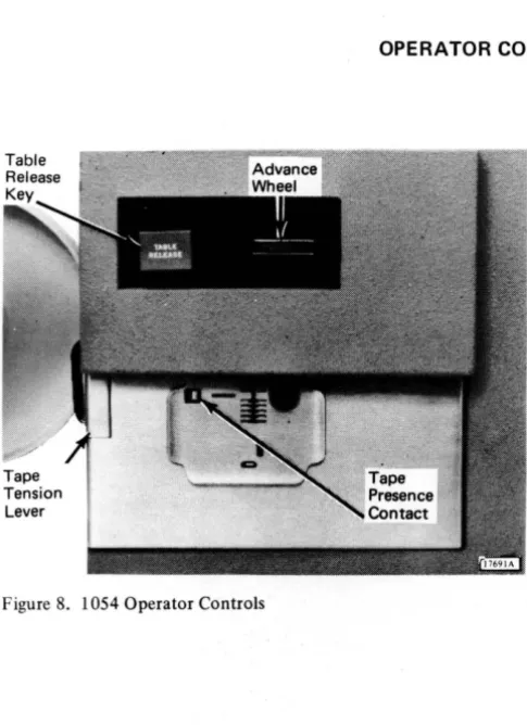
[image:20.607.31.274.391.725.2]OPERATOR CONTROLS (Figure 8)
Figure 8. 1054 Operator Controls
16 IBM 1800 Operating Procedures
The Table Release Key, when pressed, causes the tape guide to raise, permitting insertion or removal of previously punched tape.
The Advance Wheel permits tape to be moved forward or backward while maintaining proper registration. Reading does not occur during this movement.
The Tape Tension Lever actuates a switch which signals a not ready condition if too much tension is placed on the tape as it feeds through the unit.
IDENTIFYING START OF TAPE
1.
j:
Data Channels
~
!-
Feed HoleTAPE MOTION
Q
!
i
2.
Start of tape is identified by either the pointed end of the tape or a mark made to identify start of tape. When loading tape, start of tape should be pointing in the direction of tape movement and the channels should appear as shown at the left. If the channels are reversed, the tape is upside down and must be turned over.
LOADING PUNCHED TAPE
1. Press TABLE RELEASE.
2. Lightly push tape across table toward back of reader, inserting it under tape guides (A). Make sure that top edge of tape is aligned against registration rail (B) at back of table.
3. Move tape either right or left to position a tape column under red line (C) of guide.
4. Press table down to latch it in position. Using advance wheel (D), move tape right or left to ascertain that tape moves freely under guide.
18 IBM 1800 Operating Procedures
6. Hold inner cylinder (E) of take-up reel. Although reel is free-running while power is on, any slight hand pressure will stop it.
7. Grasp outer cylinder of reel and turn slightly counter-clockwise.
8. Pull outward on outer cylinder and reel will separate.
9. Thread tape through guides (F) on right side of reader.
10. Insert tape in slot of take-up reel.
11. Replace outer cylinder (G), turning it slightly clock-wise to lock it in place.
LOADING A TAPE LOOP
A tape loop requires the same loading procedure as normal punched tape. The following suggestions permit loading a tape loop with a minimum of effort.
1. The tape loop should be long enough to feed freely around the tape guides without dragging on the guide edges. However, it should not be long enough to drag on the floor.
2. The loop should also be very clearly marked for: a. Starting position of the loop.
SPLICING PAPER TAPE
Leader • • •
TAPE
~
: : :•••••••••••
MOTION • • •
•••
•••
Delete • • •
Characters ~
Leader
TAPE
~
••••••
•••••
MOTION
•
•••
••
•••
Trailer
•
••••••••••
•
••
• ••
•
••
• • • Delete ~ Characters
• • • Trailer
•••
•••
••••••••••••
•••
•••
• • • Overlap • • • Delete ~ Characters
!
l. 2.
3 .
4 .
5.
6 .
7.
Prepare a leader of at least three delete characters. Prepare a trailer containing the same number of delete characters as leader .
Make straight-edge cut to terminate both leader and trailer .
If tape is Mylar* Tape, remove glaze from bottom of trailer and top of leader with ink eraser to provide a better bonding surface.
Apply tape glue (IBM part 221030) to either top of leader or bottom of trailer and allow glue to become tacky .
Lap leader edge under trailer edge, aligning delete characters and feed holes for registration . Press tape firmly together to form d proper bond and then allow glue to dry.
CLEARING ERROR CONDITIONS
l. Verify that tape is aligned against registration rail. Occasionally it is not properly registered and feeding is accomplished by the feed pins actually using the data holes as feed holes.
2. Verify that tape is not inserted backwards.
3. 4.
5.
Verify that a tape jam has not occurred.
Verify that tape tension lever has not been actuated by too much tension on tape.
I
This page left blank intentionally.
The IBM 1055 Paper Tape Punch provides paper tape
output for the 1800 system. The 1055 (maximum of one per system) operates under direct control of the stored program and punches I-inch, eight-track chad paper tape
(holes completely punched). The punching speed is 14.8
characters per second.
Paper tape punching is initiated by a write command
issued to the 1055. The write command causes the data in the main storage location specified by the command to be punched into the paper tape. The tape is then moved one character position.
Characters are punched in the paper tape as an image of the data contained in main storage locations. One tape character is punched from each main storage location.
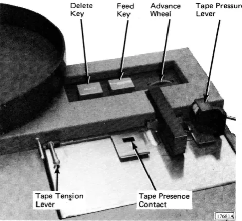
OPERATOR CONTROLS (Figure 9)
Figure 9. 1055 Operator Controls
22 IBM 1800 Operating Procedures
The Delete Key is used to advance the tape by punching
a delete character and a feed hole. Delete characters are punched continuously by pressing and holding DELETE
and FEED.
The Feed Key is used to advance the tape by punching
feed holes. Feed holes are continuously punched by holding FEED down.
The Advance Wheel permits the tape to be moved forward
or backward without punching. If the tape is moved forward, exercise care since no feed holes are punched with this operation.
The Tape Tension Lever actuates a switch which signals a
not ready condition if too much tension is placed on the tape as it feeds from the tape supply pan.
The Tape Presence Contact signals a not ready condition
when the punch runs out of tape.
The Tape Pressure Lever holds the tape against the feed
wheel to ensure proper feeding. During tape punching, this lever is in the down position (active). When tape is being inserted, this lever must be raised until the tape is
[image:26.602.36.272.280.495.2]LOADING BLANK TAPE
1. Lift tape pressure lever (A) clockwise 90 degrees. (System power should be on.)
2. Place reel of blank tape in tape supply pan (B). Supply pan should turn counterclockwise when tape is pulled.
3. Pull tape until about 30 inches extend beyond tape supply pan.
4. Thread leading edge of blank tape over guide pin (C) and under tape tension lever (D). Outside surface of tape in supply pan should be face up under tape tension lever.
5. Slide blank tape under tape guide (E), punch die (F), and tear guide (G). If punch has a take-up reel - a special feature - continue with following steps. If punch does not have take-up reel, proceed to step 11.
6. Hold inner cylinder (H) of take-up reel. Although reel is free-running while power is on, any slight hand pressure stops it.
7. Grasp outer cylinder and turn slightly counterclock-wise. Pull outward on outer cylinder and reel will separate.
8. Thread tape around two guides (I) on right side of punch.
9. Thread tape onto inner cylinder of take-up reel. (Outer surface of tape should still be-face up.)
10. Replace outer cylinder (1) of take-up reel, turning it slightly clockwise to lock it in place.
11. Lower tape pressure lever (K) - counterclockwise 90 degrees.
12. Press and hold feed key until 4 to 6 inches of tape have been punched. (If delete characters are desired, press and hold DELETE and FEED.) This action permits self-alignment of tape for proper punching registration.
24 IBM 1800 Operating Procedures
REMOVING PUNCHED TAPE
1. Press FEED to prepare a trailer of at least 6 inches of tape. (If delete characters are desired, press and hold FEED and DELETE.)
2. Tear tape at tape tear guide (A) with upward motion. This identifies start of next tape and end of previous tape. If tear guide is not used, make sure end of punched tape and start of next tape are identified by some sort of marking. If punch has a take-up reel, continue with step 3.
3. Hold inner cylinder (B) of take-up reel. Although reel is free-running while power is on, any slight hand pressure stops it.
4. Grasp outer cylinder and turn it slightly counter-clockwise. Pull outward on outer cylinder and reel will separate. Punched tape can now be removed.
5. After punched tape has been removed, press FEED to feed enough tape for threading through guides on side of punch. (If delete characters are desired, press and hold FEED and DELETE.)
6. Thread tape through guides (C) on right side of unit and onto inner cylinder. Outer surface of tape in tape supply pan should be face up on inner cylinder of take-up reel.
7. Replace outer cylinder (D) of take-up reel, turning it slightly clockwise to lock it in place.
EMPTYING THE CHAD BOX
1.
2.
CLEARING A NOT READY CONDITION
Verify that tape tension lever is not actuated. When actuated, tape tension lever is up and forward from its normal position.
Verify that tape pressure lever is down and holding tape against feed wheel.
3. 4.
I
This page left blank intentionally.
IBM 1442 Card Read Punch
The IBM 1442 Card Read Punch provides card input/output for the 1800 system. The 1442's (m<Lximum of two per system) operate under data channel control. They transport the cards through the unit and accomplish reading and punching as directed by the stored program. Maximum machine speeds arc:
Operation ll1.odel Speed
Read 6 300 cards per minute
7 400 cards per minute
Punch 6 80 columns per second
7 160 columns per second
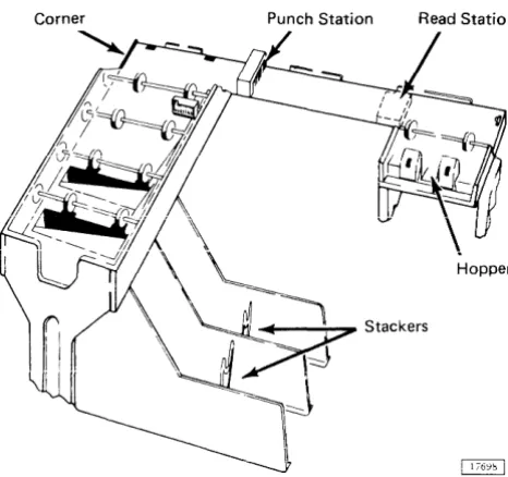
Cards are placed in the hopper face down, 9-edge first. The hopper holds approximately 1,200 cards. Cards are fed from the hopper 9-edge first. Figure 10 illustrates the path cards follow during reading and/or punching operations.
Card Reading
Card reading is initiated by a program read command. If the 1442 is in ready status, the card at the read station is registered and fed through the read station. This feed causes columns 1 through 80 of the card to be read in one continuous motion. The card is read serially - that is, column by column - beginning with column 1. Reading is
Punch Station Read Station
Hopper
Figure 10. 1442 Card Path
28 IBM 1800 Operating Procedures
accomplished through photocell sensing. Each column is read twice by the photocells. and the readings are compared for agreement. As each column is read. the data is trans-ferred to the processor-controller via data channel (cycle steal) operation.
After a read operation is completed, the card is reg-istered at column 1 in the punch station.
Card Punching
Card punching is initiated by a program write command. If the 1442 is in ready status and a card is registered at the punch station, a column of data is requested and trans-ferred to the 1442 via data channel (cycle steal) operation. An incremental punch drive causes the card to be punched and then incremented one column. The cards in the hopper and read station are not moved. The data transfer and punch operation continues until a signal indicating last column is received from the program. Upon receiving this signal, the 1442 punches and then increments the card one more column. An interrupt is generated which signals the program that punching is complete. Once punching is ter-minated in this manner, it cannot be restarted in this card.
If a write command is received when the 1442 is in ready status but a card is not registered at the punch station, a feed cycle is taken to move the card from the read to the punch station. Punching then proceeds as described in the preceding paragraph.
Punch checking is accomplished by comparing punch echo data (created by the actual punching motion) with the character sent to be punched.
Card Feed
Cards are moved through the 1442 in cycles. During a feed cycle, the card at the punch station is transported through the punch station to the stacker, a card at the read station is transported through the read station and regis-tered at the punch station, and the bottom card in the hop-per is fed into the read area. All cards pass through the read and punch stations, but reading and/or punching occurs only by program command.
A feed cycle is initiated by a write command (if no card is present at the punch station), a feed command, or a read command.
Initial Program Load
Initial program load (IPL) is initiated by pressing PROG
[image:32.615.43.276.476.695.2]LOAD on the processor-controller console. During IPL, one card is read into 40 main storage locations beginning with the location specified by the I-register. Following this
load action, the processor-controller branches to location 0000 to begin program execution. The mode switch should be on RUN or Sl/CS for program operation. The 1442 designated as first on the system is used for IPL.
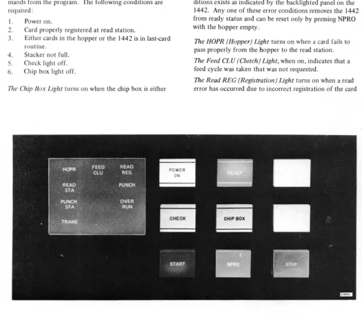
OPERATOR CONTROLS (Figure 11)
The Power On Light is on when operating power is being supplied to the 1442 control circuits.
The Ready Light is on when the 1442 is able to ac~ept com-mands from the program. The following conditions are required:
1. Power on.
2. Card properly registered at read station.
3. Either cards in the hopper or the 1442 is in last-card routine.
4. Stacker not full. 5. Check ligh t off. 6. Chip box light off.
The Chip Box Light turns on when the chip box is either
full or has been removed. This condition removes the 1442 from ready status.
The Check Light turns on when one of the eight error con-ditions exists as indicated by the backlighted panel on the 1442. Anyone of these error conditions removes the 1442 from ready status and can be reset only by pressing NPRO with the hopper empty.
The HOPR (Hopper) Light turns on when a card fails to pass properly from the hopper to the read station.
The Feed CLU (Clutch) Light, when on, indicates that a feed cycle was taken that was not requested.
[image:33.607.45.570.242.709.2]compare equally.
The Read STA (Station) Light. when on, indicates that a card was not properly positioned (feed check) at the read sta tioll.
The Punch Light turns on when a punch check occurs due to failure of the punch echo data and punch character to compare equally. Punching into prepunched columns does not cause a punch check.
The Punch STA (Station) Light, when on, indicates that a card was not properly positioned (feed check) at the punch station.
The Overrun Light turns on when data overrun occurs. That is, data was lost because the data channel failed to transfer data to or from main storage within the time the 1442 required service.
The TRANS (Transport) Light, when on, indicates that a card is out of position in the card transport area between the punch station and stackers.
Thp Start Ke.v is llsed to perform the following functions:
1. To start initial card run-in. The bottom card in the hopper moves to the read area and ready sta tus is restored to the 1442.
2. To restore ready status after manually stopping the 1442.
3. To initiate a last card sequence.
The Stop Key removes the 1442 from ready status when it is pressed. If a 1442 operation is in progress, it is neces-sary to hold STOP down until the operation is complete; otherwise the 1442 will not recognize that STOP has been pressed.
The NPRO (Nonprocess Runout) Key is used to eject cards from the serial path without processing them. Pressing NPRO also resets the eight error conditions. This key is effective only if the hopper is empty. During card opera-tions, NPRO should not be held down at the time the hop-per goes empty, as the signal to the program indica ting that the operation is complete for the last card processed will not be given.
READYING THE 1442
1. With system power on, press NPRO to clear any error condition and eject any cards left in card path.
2. 3.
Place cards face down in hopper, 9-edge first. Press START. When ready light comes on, 1442 is in ready status.
INITIATING LAST CARD SEQUENCE
When the hopper goes empty during a feed cycle, the 1442 is removed from ready status. This signals the program that operator intervention is required.
Processing may be continued by loading more cards into the hopper and pressing START. A last card sequence may be initiated by pressing START without loading more cards
30 IBM 1800 Operating Procedures
in the hopper.
The last card sequence places the 1442 in ready status and allows two more feed cycles to be taken. The last two feed cycles allow processing of the last card and ejects it into the stacker. The program is also signalled that the last card has been processed.
CLEARING CARD JAMS
The check light, along with a read station, punch station, or transport light, indicates a card jam condition. A card saw
should not be used to remove ajam in the punch station as
the punch mechanism could be damaged. The following steps are recommended to remove jammed cards.
1. Remove cards from hopper.
2. Raise two top covers. (Raise cover on right (A)
first, then cover on left (B).)
3. Locate card jam. If card jam is not in punch station
(C), remove jammed cards and proceed with steps 4
through 6. If card jam is in punch station, proceed
with step 7.
4. Close covers and press NPRO to re'set error condition
and run out any cards in card feed or transport areas. 5". Reconstruct any damaged cards and place card deck
back into hopper.
6. Press START. This places 1442 in ready status by
initiating a run in cycle.
7. Turn two twist-type fasteners (D) on inside of rear
cover counterclockwise and lower cover.
8. With power on, rotate punch unit handwheel (E) in
direction of arrow at least one-half revolution.
9. Push down on punch feed release lever (F) and pull
out card. If card remains jammed, loosen lower punch guide holding screw (G) and remove lower punch guide. If necessary, raise plastic card guide (H). The card should now be easily removed.
10. Replace lower punch guide if it was removed.
Punch Station Read Station
I
Hopper
_--;--~ Stackers
Feed Check (punch station) indicates that card 1 is im-properly positioned in punch station at completion of its feed cycle.
Error Indication: PUNCH STA and CHECK.
Card Positions After Error: Shown at left.
Procedure: 1. When program halts, empty hopper and clear 1442 card path.
2. Place cards 1 and 2 in front of card 3 and return deck to hopper.
3. Press START to ready 1442.
Transport indicates that card 1 has jammed in area between punch station and stacker during feed cycle for card 2.
Error Indication: TRANS and CHECK.
Card Positions After Error: Shown at left.
Procedure: 1. When program halts, empty hopper and clear 1442 card path.
2. Place cards 2 and 3 in front of card 4 alld return deck t\J hopper.
3. Press START to ready 1442.
Feed Cycle indicates that 1442 took an unrequested feed cycle and, therefore, cards 1,2, and 3 are each one station farther ahead in 1442 card path than they should be.
Error Indication: FEED CLU and CHECK.
Card Positions After Error: Shown at left.
Procedure: 1. When program halts, empty hopper and press NPRO to eject c~lfds 2 and 3. 2. Place cards 1, 2, and 3 in front of card 4
and return deck tu ho·pper. 3. Press START to ready 1442.
Hooper
---'\---;;:>, Stackers
Hopper
_ - - - ; ; - - ; 7 Stackers
~
~StaCkers
~
Feed Check (read station) indicates that card I failed to eject from read station during its feed cycle.
Error Indication: READ ST A and CHECK.
Card Positions After Error: Shown at left.
Procedure: 1. When program halts, empty hopper and clear 1442 card path.
2. Place cards 1 and 2 in front of card 3 and return deck to hopper.
3. Press START to ready 1442.
Read Registration indicates incorrect card registration or -a difference between first and second reading of a card
column.
Error Indication: READ REG and CHECK.
Card Positions After Error: Shown at left.
Procedure: 1. When program halts, empty hopper and clear 1442 card path.
2. Place cards 1 and 2 in front of card 3 and return deck to hopper.
3. Press START to ready 1442.
Punch Check indicates an error in output punching.
Error Indication: PUNCH and CHECK.
Card Positions After Error: Shown at left.
Procedure: 1. When program halts, empty hopper and press NPRO to eject cards 1 and 2. 2. If necessary, reconstruct card 1 to
pre-punched state.
3. Place reconstructed card 1 and card 2 in front of card 3 and return deck to hopper.
Overrun
(read operation) indicates that data was lost be-cause the data channel failed to transfer data to main storage within the time the 1442 required service.Error Indications: OVERRUN and CHECK.
Card Positions Mter Error: Shown at left.
Procedure: 1. When program hal ts, empty hopper and press NPRO to eject cards 1 and 2. 2. Place cards 1 and 2 in front of card 3 and
return deck to hopper. 3. Press START to ready 1442.
Overrun
(punch operation) indicates that data was lostbe-cause the data channel failed to transfer data from main storage within the time the 1442 required service.
Error indication: OVERRUN and CHECK.
Card Positions Mter Error: Shown at left.
Procedure: 1. When program halts, empty hopper and press NPRO to eject cards 1 and 2. 2. If necessary, reconstruct card 1 to
pre-punched state.
3. Place reconstructed card 1 and card 2 in front of card 3 and return deck to hopper. 4. Press START to ready 1442.
Parity
(read operation) indicates incorrect (even) paritydetected on data transfer to processor-controller.
Error Indication: No 1442 error lights will be on.
Card Positions After Error: Shown at left.
Procedure: 1. When program halts, empty hopper and press NPRO to eject cards 1 and 2. 2. Place cards 1 and 2 in front of card 3 and
return deck to hopper. 3. Press START to ready 1442.
Parity (punch operation) indicates incorrect (even) parity detected on data transfer from processor-controller.
Error Indication: No 1442 error lights will be on. Card Positions After Error: Shown at left.
Procedure: 1. When program halts, empty hopper and press NPRO to eject cards 1 and 2. 2. If necessary, correct card 1 to
pre-punched state.
3. Place corrected card 1 and card 2 in front of card 3 and return deck to hopper. 4. Press START to ready 1442.
Storage Protect indicates attempt to read a column into a
storage-protected location.
Error Indication: No 1442 error lights will be on.
Card Positions After Error: Shown at left.
Procedure: 1. When program halts, empty hopper and press NPRO to eject cards 1 and 2. 2. Place cards 1 and 2 in front of card 3 and
return deck to hopper. 3. Press START to ready 1442.
Chip Box indicates that chip box is full or has been removed from the machine.
Error lndication: CHIP BOX.
Procedure: l. Open front left door (A) of 1442. 2. Using handle (B), pull box from unit
and empty.
3. Replace box and close door.
1443
Printer
IBM 1443 Printer
The IBM 1443 Printer prov