Technology (IJRASET)
Digital Analysis Of Fir Low Pass Filters Using
Bartlett And Bartlett Hanning Windows
K Sneha Rao1, Prabha Singh2,Manoj Singh3, Pranay Kumar Rahi
1,2,3
BE Scholar,4Assistant Professor
1,2,3,4
Department of Electrical & Electronics Engineering Institute Of Technology Korba Korba, Chhattisgarh, India
Abstract: In today’s world digital filter plays an important role in the field of communication and computation. Without digital filter proper communication is not possible because of noise present in the communication channels. For removing the noise various types of digital filters are used and designed . Window techniques are used to design the digital filters. In this paper, we have designed the low pass fir digital filter using bartlett & bartlett hanning window techniques of order 13 by simulating the code in matlab. The matlab program gives satisfactory results with proper magnitude, phase and frequency response plotting. Keywords:- DSP, IIR, FIR, PSE, BARTLETT & BARTLETT HANNING.
I. INTRODUCTION
Signal processing is an enabling technology that encloses the fundamental theory, applications, algorithms and implementation of processing or transferring information contained in many different physical symbolic or abstract formats broadly designated as signals. The signal processed in DSP are a sequence of numbers that represents samples of a continues variable in a domain such as time, space or frequency.[1]
Digital signal processing is an area of science and engineering that has developed rapidly. Digital signal processing (DSP) refers to various techniques for improving the accuracy and reliability of signal processing. The theory behind DSP is quite complex. Basically, the DSP works by clarifying, or systematizing, the level or states of a digital signal.[2]
In particular digital processing hardware allows programmable operations. Through software one can more easily modify the signal processing functions to be performed by the hardware. Thus digital hardware and associated software provide a greater degree of flexibility in filter design. For all this reasons there has been rapid growth in digital signal processing theory and applications over the past three decades.[3]
A. Applications
The main applicationsof DSP are audio signal processing, audio compression, digital image processing, video compression, speech processing, speech recognition, digital communications, digital synthesizers, radar, sonar, financial signal processing, seismology and biomedicine. Specific examples are speech compression and transmission in digital mobile phones, weather forecasting, seismic data processing, image processing, data compression, economic forecasting, analysis and control of industrial processes, spectral analysis and sound reinforcement applications, medical applications such as CT scans and MRI scans, Mp3 compression, computer graphics, channel vocoders, hi-fi loudspeaker crossovers and equalization, homomorphic processing systems, analysing the signals in radar tracking and audio effects for use with electric guitar amplifiers.[1]
B. Advantages
1) The digital signals are fairly immune to the imperfections of real electronic systems which tend to spoil analog signal. 2) A digital signal can be programmably changed to change the functionality.
3) Ease of upgrading and flexibility.
4) It is less sensitive to the environmental changes so its stability is more. 5) DSP based systems can be easily modified.
C. Disadvantages
1) COST: DSP design cost can be very high when large bandwidth signals are involved. And also the analog to digital converter or digital to analog converter device prices are high for large bandwidth.
Technology (IJRASET)
Bandwidth upto 100MHz range are still being processed by analog methods since the DSP methods are available not faster enough.
3) DESIGN Time: It may take long time for DSP design so, you should have a skilled, and perfect people who knows well about DSP techniques.
4) POWER: This is one of the main disadvantage of DSP. DSP chips contain over 4 lakh transistors which dissipates power around one watt.
D. Digital Filters
Digital filters are widely used in the world of communication. A digital filter is mathematical algorithm implemented in hardware/software that operates on a digital input to produce a digital output.
Digital filter clipper from conventional analog filters by their use of finite precision to represents signals and coefficient and finite precision arithmetic to compute the field response.
1) Digital filters are classified either as a) Finite duration impulse response b) Impulse duration impulse response
In signal processing FIR filter is a filter whose impulse response or response to any finite length input is of finite duration , because it settles to 0 (zero) in finite time. The IIR system has an infinite number of non-zero terms, i.e. its impulse response sequence is of infinite duration.[5]
2) FIR filters have the following advantages over IIR filters a) They can have an exact linear phase.
b) They are always stable.
c) The design methods are generally linear. d) They can be realised efficiently in hardware. e) The filter start-up transients have finite duration.
FIR filters are employed in filtering problems where linear phase characteristics within the passband of filter is required. If this is not required, either an IIR or a FIR filter may be employed.[4]
II. WINDOW TECHNIQUE
In the window design method, one first designs an ideal IIR filter and then truncates the infinite impulse response by multiplying it with a finite length window function. The result is a finite impulse response filter whose frequency response is modified form of the IIR filter.[5]
A. Bartlett Window Function
The window function of Bartlett window is given by
W Bart(n) = {
, , ,
B. Bartlett Hanning Window Function
The window function of Bartlett hanning window is expressed by
( ) = −
− − − −
III. SIMULATION AND RESULTS
Parameters Values Sampling frequency(Fs) 48000
Cut off Frequency(Fc) 10800
Technology (IJRASET)
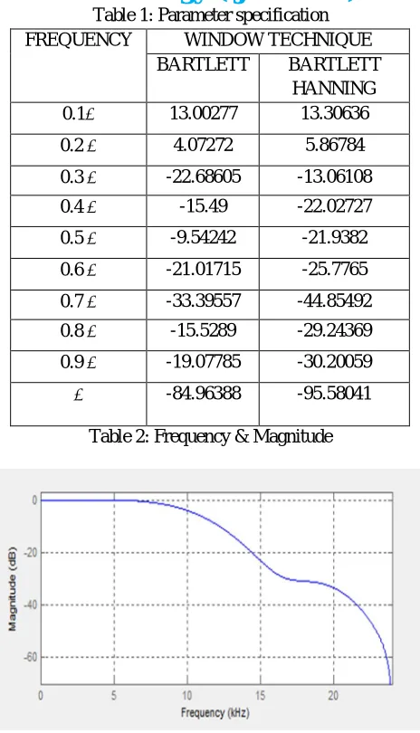
Table 1: Parameter specification FREQUENCY WINDOW TECHNIQUE
BARTLETT BARTLETT HANNING 0.1 13.00277 13.30636
0.2 4.07272 5.86784
0.3 -22.68605 -13.06108
0.4 -15.49 -22.02727
0.5 -9.54242 -21.9382
0.6 -21.01715 -25.7765
0.7 -33.39557 -44.85492
0.8 -15.5289 -29.24369
0.9 -19.07785 -30.20059
[image:4.612.190.422.74.479.2]-84.96388 -95.58041
Table 2: Frequency & Magnitude
Figure 1: Bartlett Window Technique`s magnitude response
[image:4.612.190.422.506.698.2]Technology (IJRASET)
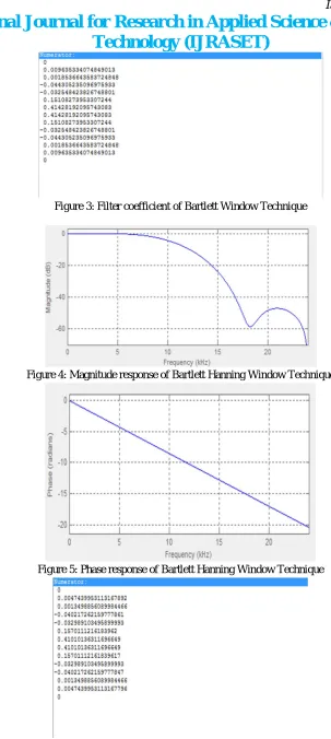
Figure 3: Filter coefficient of Bartlett Window Technique
Figure 4: Magnitude response of Bartlett Hanning Window Technique
Figure 5: Phase response of Bartlett Hanning Window Technique
Technology (IJRASET)
Figure 7: Time domain and Frequency domain of Bartlett Window Technique
Figure 8:Time domain and Frequency domain of Bartlett Hanning Window Techniques
IV. CONCLUSION
In this research paper, Low pass filter has been designed and simulated using two different Window Techniques namely Bartlett and Bartlett Hanning. By analysing the performance of proposed FIR Filter by their magnitude and phase response using MATLAB simulation at same values of sampling frequency 48kHz, cut off frequency 10.8kHz and order of 13, it conclude that Bartlett Hanning Window has better passband response as compare to Bartlett Window technique. So it states that Bartlett Hanning technique is perfect than Bartlett technique.
REFERENCES
[1] https://en.m.wikipedia.org>wiki>Signal_processing.
[2] Whatis.techtarget.com/definition/digital-signal-processing-DSP
[3] John G.Proakis ,Dimitris G. Manolakis “Digital Signal Processing , Principles , Algorithms and Applications “ PEAESON , 4th Edition 2008.
[4] S.Salivahanan, C Gnanpriya, A Vallavaraj “Digital Signal Processing “, Tata Mc Graw-Hill, second edition 2010.
Technology (IJRASET)
[6] Suman Mahant, Pooja Singh Chandel, Pranay Kumar Rahi” Designing a low pass FIR Digital filter by using Bartlett Hanning And Blackmann Harris Window
Techniques”(IJSRET),ISSN 2278-0882,Volume 5,Issue 8,August 2016
AUTHORS
K Sneha Rao Pursuing bachelor of Engineering in Electrical and Electronics Engineering in 4th semester, from Institute of Technology Korba, Chhattisgarh Swami Vivekananda Technical University, Chhattisgarh, India.
Prabha Singh Pursuing Bachelor of Engineering in Electrical and Electronics Engineering in 4th semester from Institute of Technology Korba, Chhattisgarh Swami Vivekananda Technical University, Chhattisgarh, India.
Manoj Singh Pursuing bachelor of Engineering in Electrical and Electronics Engineering in 4th semester, from Institute of Technology Korba, Chhattisgarh Swami Vivekananda Technical University, Chhattisgarh, India.