© 2015, IRJET ISO 9001:2008 Certified Journal Page 60
A NOVEL UNIFIED DATA EMBEDDING TECHNIQUE
SWETHA KRISHNAN, R. ANIL KUMAR
1
Student MTech VLSI and Embedded System, Viswajyothi College of Engineering and Tech., Kerala, India
2Assistant Professor, Electronics and communication, Viswajyothi College of Engineering and Tech., Kerala, India
---***---Abstract -
Data embedding techniques aim atmaintaining high-output image quality so that the difference between the original and the embedded images is imperceptible to the naked eye. Recently, as a new trend, some researchers exploited reversible data embedding techniques to deliberately degrade image quality to a desirable level of distortion. In this paper, a novel unified data embedding technique is proposed to achieve two objectives simultaneously, namely, high payload and adaptive scalable quality degradation. First, a pixel intensity value prediction method called checkerboard based prediction is proposed to accurately predict 75% of the pixels in the image based on the information obtained from 25% of the image. Then, the locations of the predicted pixels are vacated to embed information while degrading the image quality. Data embedding aims to utilize content (e.g., image) as a venue to host external information. On the contrary, purpose of DCT is to make an image distortion less by improving the quality of the image and purpose of perceptual encryption (refer to scrambling) is to make a content imperceptible by converting it into a severely distorted or meaningless form.
Key Words: Data embedding,scrambling,DCT, etc…
1.
INTRODUCTION
Internet and mobile technologies have made the storage, access, and transmission of huge amount of multimedia information more convenient. However, the prevalence of these technologies has led to serious security concerns and handling needs. Various techniques including cryptography, steganography etc. are used to secure information on the internet. Cryptography is the science of converting the messages that are intended to be secret into some other form, such that it is not understandable to anyone other than the intended sender and recipients. Steganography is a technique for securing information by hiding it in some other medium, such that the existence of information is concealed to everyone except for the intended sender and receiver. These issues have driven the research community to invent data hiding techniques. In general, a data hiding technique for digital content cans be classified into two disciplines, namely [1] data embedding and [2] perceptual encryption. Data
embedding aims to utilize content (e.g., image) as a venue to host external information. On the contrary, purpose of perceptual encryption (hereinafter refer to scrambling) is to make a content imperceptible by converting it into a severely distorted or meaningless form [1]. In this work, a novel unified data embedding technique (UES) method is proposed to degrade image quality of an image by inserting external information into it. Instead of transforming to new domain (such as Universal Domain in [10]) or finding some features suitable for data embedding, external information are inserted into selected pixel locations by direct replacement. Pixel intensity values are first predicted by using the proposed novel prediction method, and then the selected locations among the predicted pixels are vacated and replaced by the external information. In addition, UES can operate in two modes, namely, lossless to allow perfect restoration of the original host image, or lossy to accommodate high payload. This work can be considered as an image encryption method with added feature of reversible and irreversible data embedding. Nonetheless, from the perceptive of data.
1.1 Literature Survey
© 2015, IRJET ISO 9001:2008 Certified Journal Page 61 domain can be further into three sub-categories, namely,
compress-and-append, expansion based (EB) and Histogram shifting (HS). A scalable scrambling method with reversible data hiding functionality was proposed in DCT compressed domain was proposed by wong [3]. Among the available image and video compression standards, the DCT based standards remain the mostly considered ones due to their high quality to compression ratio and the number of existing hardware that support these formats. Therefore, there is a need of continued research in data hiding for the future of DCT based compressed contents. Most of the existing scrambling methods focused on security and computation complexity but neglected visual appearance of the scrambled image. For image vendor, it is desirable to produce an image that shows partial detail to attract interested parties while preventing unauthorized, without reconstruction, without the decoding key. Scalable scrambling is a solution to such scenario because it produces image with desired level of distortion while preserving some visual details. At the same time, it will be beneficial to insert information such as resolutions of the image available for purchase, price list, vendor's information, ownership, etc. that stays intact with the partially scrambled image. To the best of knowledge, the scrambling method by Takayamaet al is the only existing work that provides scalable scrambling feature in the DCT compressed domain.
Instead of attempting to suppress quality degradation due to data insertion, Wong utilized this distortion to achieve scalable scrambling effect. In his work, a scalable scrambling method in the DCT compressed domain was proposed while inserting external information into the content, and this method is the first attempt of its kind. It is achieved by scalable scrambling effect by scrambling DC components using a window of varying size while external information is encoded by imposing a specific relationship on the cardinality of two adjacent coefficient blocks. Ong et al. proposed scalable visual quality degradation, by mapping all pixels in the predetermined block to their corresponding mirror values for data embedding purposes Quality of the embedded-scrambled image is further degraded by shuffling pixels in blocks of predefined size.
Prediction of pixels is one of the possibilities for design of the modeling phase. Pixel prediction means that for every pixel in the image, its value is guessed. The idea behind this is that the differences between the predictions and the real values of the pixels are ideally zero. Since the prediction function is not perfect and usually makes (some) errors, those differences will generally be close to zero. This distribution of values is far more suited for compression than is the original, random distribution of the values. The challenge of this all comes from the fact that, while decoding the compressed image, the algorithm can only make use of the pixel values that are already decoded. So, the compression algorithm should only make
use of those pixels that would be available to the decompression algorithm in the corresponding stage of the decoding. Some of existing pixel value predictors are GAP (Gradient Adjusted Prediction) in CALIC (Context Adaptive Lossless Image Compression) compression system, DARC, GBSW (Gradient-Based Selection and Weighting), and GBTA (Gradient-Based Tracking and Adapting).
The limitations of existing predictors is that their prediction accuracy decreases when handling image of high spatial activity and vice versa. Due to the design of the conventional predictors, the earlier predicted pixels are required to carry out the (immediate) next prediction process, i.e., the dependency is cascaded from the last pixel to the first pixel in the image in the worst case scenario. Therefore, the architecture of the conventional predictors has a low degree of parallelism. The computation complexity is also more in conventional predictors. In this method, an efficient pixel intensity value prediction method, called Checkerboard Based Prediction (CBP), is proposed to accurately predict 75% of the pixels in the host image prior to data embedding. Then, data embedding is achieved by directly replacing the pixel values by the external information.
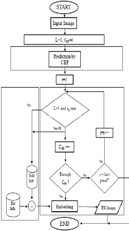
2. Unified Embedding Technique
The proposed method consists of three main processes, namely, pixel value prediction, information embedding, and reconstruction. These processes are elaborated in the following sub-sections
Fig 2.1. Block Diagram of Unified Embedding Technique
2.1 Checkboard Based Prediction (CBP)
© 2015, IRJET ISO 9001:2008 Certified Journal Page 62 limitation of MED is that, by the first two conditions in
Equation , the pixels are duplicated because the predicted value is either exactly N or W, and it always falls within the range of min(N,W) and max(N,W) .
(2.1)
where max (N,W) and min(N,W) return the maximum The prediction scheme of the proposed algorithm depends on the location of the current pixel. Consider the three adjacent pixels, N, NW and W, of the current pixel X. Let Xc , Nc , NWc and Wc represent the pixel color values of X, N,NW and W', and respectively. The prediction scheme uses the following rules to estimate the color value of X.1. If the current pixel is the top leftmost one; then there is no prediction since there are no adjacent pixels and no prior information for prediction. So in this case, X ' =0, otherwise,
2. If the current pixel X is not the top leftmost one but is in the first row, then X ' = Wc, otherwise,
3. If the current pixel X is not the top leftmost one but is in the first column, then X ' = Nc, otherwise,
[image:3.595.328.552.216.321.2]4. In this case, the current pixel X has all three adjacent pixels. If at least two of the three adjacent pixels have their colors located in the same quantized color regions, X ' = the average value of the color values of these pixels; otherwise, the three adjacent pixels have their colors located in different quantized color regions, and so X ' = the average value of the color values of the three pixels. To find which quantized color region a pixel color belongs to, we can simply search for the region that has the nearest centroid from the pixel color.
Figure 2.2. The positions of three adjacent pixels N, NW and W of the current pixel X
Based on empirical results, there are two parameters essential and crucial for accurate pixel value estimation. In particular, they are: (a) the distance from the target pixel - since closer neighboring pixels have higher correlation with the target pixel [refer to
Fig. 2.2(a)], and (b) the bidirectional information around the target pixel - since by knowing the value of both the previous and next pixels in various directions, the pattern of the target pixel can be accurately approximated [refer to Fig. 2.3(b)]. Therefore, CBP (Checkerboard Based Prediction) is proposed as an efficient pixel estimation technique which can be independently exploited in various applications, including decorrelation, compression, data embedding, etc.
Figure 2.3. Essential parameters for accurate pixel
prediction. (a) Distance from the target pixel. (b) Bidirectional information around the target pixel.
First, every other row and column of pixels are stored to be utilized as the reference points to predict the rest of the pixels (i.e., store 25% of the pixels in raw values to predict the remaining 75%) as shown in Fig. 2.3(a). Then, pixel value estimation is invoked in two passes. In the first pass, pixels marked as ‘X’ in Fig. 2.3(b) are predicted. Next, those slightly shaded pixels marked are predicted in the second pass. The pixel values are estimated using Eq. (2.2) and Eq. (2.3) in the first and second passes, respectively, where rnd(·) denotes the rounding operation
(2.2)
(2.3)
[image:3.595.322.547.500.671.2]© 2015, IRJET ISO 9001:2008 Certified Journal Page 63 Figure 2.4. Neighborhood of target pixel ‘X’
Then, the prediction errors are captured as side information and the locations of the predicted pixels are vacated for data embedding purposes.
2.2.
UNIFIED EMBEDDING-SCRAMBLING (UES
)
In the process flow of the proposed embedding-scrambling method, first, the proposed CBP is utilized to predict pixel values in the image. Next, each prediction error, denoted as ep for the rest of the presentation, is
computed as ep= x – xp where x and xp are the original and
predicted value by CBP, respectively. Then, ep is analyzed
to decide if the corresponding pixel location is suitable for data embedding. In particular, if ep falls within a
predefined range as expressed in Eq 2.4,
-ε ≤ ep ≤ ε (2.4)
Where ε ∈ N, then it is utilized for data embedding
purpose. Otherwise it will be left unmodified.
In particular, we classify all pixels in an image into three categories, namely, (a) not-predicted (NP), (b) predicted but not embedded (PN) and, predicted-and-embedded (PE). Here, the set of NP consists of all the reference points in every other column and row, which are utilized to predict the rest of the pixels using the proposed CBP method. Next, PN refers to a pixel whose ep fails the
condition in Eq. (3.4). In other words, PN is a pixel that cannot be predicted accurately by the proposed CBP method, and it is not considered for data embedding. Thus, PN holds the original pixel value. Finally, PE refers to a pixel that satisfies Eq. (2.4), and it is utilized for data embedding. Here, the prediction errors ep are stored as
side information to reconstruct the original image. It is worth emphasizing that due to the nature of CBP, unlike expansion based and histogram shifting methods, the proposed reversible embedding-scrambling method never faces the over/under flow issue. Therefore, location map is not needed to mark the usability of each pixel.
3. METHODOLOGY
A practical method based on the Framework “UES”, primarily consists of four stages: generation of
predicted pixels, data hiding in predicted pixels, data extraction and image recovery. The level 1 embedding is shown here. As level increases it is found difficult to reconstruct the original image. The embedding is also possible if and only if the error ep is minimum. The ep
[image:4.595.347.572.253.655.2]indicates the difference between the original and predicted pixels. If it is minimum then only original image reconstruction will be possible. The amount of data that can be embedded depends on the predicted pixels. If the pixels are minimum then a small amount of data could be stored in it. The extraction process is the reverse.
© 2015, IRJET ISO 9001:2008 Certified Journal Page 64 actual intensity value is stored (i.e., NP and PN), no
information is embedded. In other words, the pixel value is either not predicted (NP) or it is predicted but not vacated for data embedding (PN) because the error fails Eq. (2.4). Therefore, there is no embedded information to be extracted and there is no modification on the host image which needs to be restored.
3.1. Proposed Method
A Discrete Cosine Transform (DCT) expresses a finite sequence of data points in terms of a sum of cosine functions oscillating at different frequencies. DCTs are important to numerous applications in science and engineering, from lossy compression of audio (e.g. MP3) and images (e.g. JPEG) (where small high-frequency components can be discarded), to spectral methods for the numerical solution of partial differential equations. The use of cosine rather than sine functions is critical for compression, since it turns out (as described below) that fewer cosine functions are needed to approximate a typical signal, whereas for differential equations the cosines express a particular choice of boundary conditions.
The basic block diagram for performing DCT is shown in the figure 3.2. The input image will be RGB color image which divided to 8*8 blocks and then quantized to level 50 and then data is embedded into it. In the receiver section the reverse process is done. Each stage is explained in detail in the following section. A Discrete Cosine Transform (DCT) expresses a finite sequence of data points in terms of a sum of cosine functions oscillating at different frequencies
Figure 3.7. Block diagram of DCT process
4. Result and Discussion
Chart-1 shows the comparison chart .The embedding capacity is of .0007 bpp. The PSNR value is higher for modified unified embedding method. This shows that proposed method is better than conventional embedding technique. If we compare the processing time, then also processing time is minimum for the modified unified method.
Chart -1The Comparison Chart of PSNR using various test images
[image:5.595.351.516.287.417.2]The figure 4.10 shows the image with an embedding capacity of .0007 bppafter datahiding.
Figure 4.10. The Resultant image after data hiding
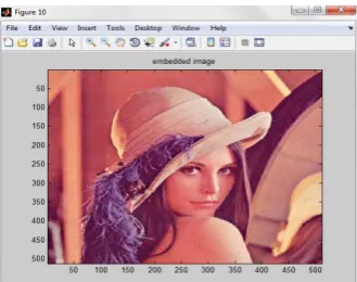
The figure 4.2 shows embedded image with payload capacity of .002 bpp.The image gets distorted as the payload capacity increases and complete recovery of original image with the same quality as that of cover image is a difficult procedure. The distorted image is easily vulnerable to attack.
Figure 4.2. The Embedded image with payload capacity .002bpp
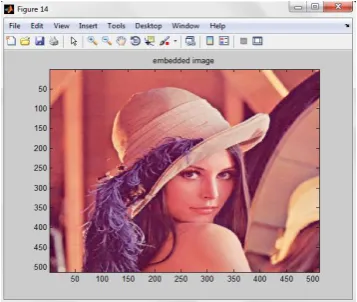
The following figure 4.3 shows embedded image with payload capacity of .004 bpp. The distortion further increases as the embedding rate increases .Here level 1 embedding is done. As the level of embedding increases it becomes difficult for the complete recovery of original
65 66 67 68 69
Lena Baboon Pepper
P
S
N
R
(d
B
)
Input image (jpeg) (.0007 bpp)
PSNR
[image:5.595.42.289.509.598.2]© 2015, IRJET ISO 9001:2008 Certified Journal Page 65 image [1].It is possible to increase the level to 2 and 3 and
[image:6.595.96.245.129.246.2]the possibility of retrieving the cover image is almost null.
Figure 4.3. The Embedded image with payload capacity .004bpp
The simulation result of DCT based technique is shown in figure 4.4. The rest of the steps are same as that of conventional method except instead of normal method, modified UES is selected and data to be embedded is also selected as done in previous method. The embedding capacity is about .0007 bpp.
Figure 4.4. The DCT based embedded image with payload capacity .0007bpp
The embedded image is having same quality as shown in figure 4.1 for higher embedding rates and it is also possible for the complete recovery of cover image. Thus no intruder could easily observe whether the image contains any data or not, and can safely send the data to the destination.
5. CONCLUSIONS
A unified data embedding method called Unified Embedding was proposed. Unified Embedding is able to severely distort the perceptual quality of the host image by means of data embedding. A pixel value predictor was proposed to predict pixel values, where the predicted pixels were replaced by the external information to be embedded. The proposed pixel prediction method can achieve accurate prediction, up to twice the accuracy of
the conventional methods. Then, the predicted pixels were selected based on their prediction errors to embed external information while their prediction errors were stored as side information.
A novel Discrete Cosine Transform (DCT) is proposed with which the quality of embedded image will not get distorted. The benefit of the DCT is that the amount of distortion can be minimized upto 90%, thus the quality of image is maintained as such. The DCT can thus be applied for higher payloads with almost minimum distortion, thus no intruder can easily aware of the data stored in it. For better security an encryption is also proposed using a different keygeneration logic and aggressor cannot easily hack the embedded image.
REFERENCES
[1] Reza Moradi Rad, KokSheik Wong, and Jing-Ming Guo, “An Unified Data Embedding and Scrambling Method,” IEEE Trans. Image Processing, vol. 23, Issue 4, pp. 1463 - 1475, Jan. 2014.
[2] I. Cox, M. Miller, J. Bloom, J. Fridrich, and T. Kalker, Digital Watermarking and Steganography. San Mateo, CA, USA: Morgan Kaufmann,2008.
[3] H. Luo, F. X. Yu, H. Chen, Zh. L. Huang, H. Li, and P. H. Wang, “Reversible data hiding based on block median preservation,” Inf. Sci., vol. 181, no. 2, pp. 308– 328, 2011.
[4] K. Wong and K. Tanaka, “DCT based scalable scrambling method with reversible data functionality,” in Proc. 4th ISCCSP, 2010, pp. 1–4.
[5] S. Ong, K. Wong, and K. Tanaka, “A scalable reversible data embedding method with progressive quality degradation functionality,SignalProcess” Image Commun., vol. 29, no. 1, pp. 135–149, 2014.
[6] X. Zhang, “Separable reversible data hiding in encrypted image,” IEEE Trans. Inf. Forensics Security, vol. 7, no. 2, pp. 826–832, Apr. 2012.
[7] M. Fujiyoshi, “Separable reversible data hiding in encrypted images with histogram permutation,” in Proc. IEEE ICMEW, Jul. 2013, pp. 1–4.
[8] K. Wong, S. Ong, and K. Tanaka, “Improvement of carrier capacity for scalable scrambling method with reversible information insertion functionality,” in Proc. IEEE ICSIPA, Nov. 2011, pp. 312–317.
[9] D. Kundur and K. Karthik, “Video fingerprinting and encryption principles for digital rights manage,” Proc. IEEE, vol. 92, no. 6, pp. 918–932, Jun. 2004.
[10] M. S. Abdul Karim and K. Wong, “Universal data embedding in encrypted domain,” Signal Process., vol. 94, pp. 174–182, Jan. 2014.
[image:6.595.72.251.368.519.2]© 2015, IRJET ISO 9001:2008 Certified Journal Page 66 [12] J. Fridrich, M. Goljan, and R. Du, “Lossless data
embedding-new paradigm in digital watermarking,” EURASIP J. Appl. Signal Process., vol. 2002, no. 2, pp. 185–196, 2002.
[13] M. Celik, G. Sharma, A. Tekalp, and E. Saber, “Lossless generalized- LSB data embedding,” IEEE Trans. Image Process., vol. 14, no. 2, pp. 253–266, Feb. 2005.
[14] J. Fridrich and M. Goljan, “Lossless data embedding for all image formats,” Proc. SPIE, vol. 4675, pp. 572–583, Apr. 2002.
[15] J. Tian, “Reversible data embedding using a difference expansion,” IEEE Trans. Circuits Syst. Video Technol., vol. 13, no. 8, pp. 890–896,Aug. 2003.
[16] D. M. Thodi and J. J. Rodriguez, “Expansion embedding techniques for reversible watermarking,” IEEE Trans. Image Process., vol. 16, no. 3, pp. 721–729, Mar. 2007.
[17] A. M. Alattar, “Reversible watermark using the difference expansion of a generalized integer transform,” IEEE Trans. Image Process., vol. 13, pp. 1147–1156, Aug. 2004.
[18] L.Kamstraand H.J.A.M. Heijmans,“Reversible data embedding into images using wavelet techniques and sorting,” IEEE Trans. ImageProcess.,vol. 14, Dec. 2005. [19] H. J. Kim, V. Sachnev, Y. Q. Shi, J. Nam, and H. G. Choo, “A novel difference expansion transform for reversible data embedding,” IEEE Trans. Inf. Forensics Security, vol. 3, no. 3, pp. 456–465, Sep. 2008.