© 2016, IRJET | Impact Factor value: 4.45 | ISO 9001:2008 Certified Journal
| Page 2290
Less Complex Channel Estimation Technique for MIMO OFDM system
1Sandeepkumar S. Gamit , 2Prof. Sarman K. Hadia , 3Prof. Dharmendra Chauhan
1M.Tech Student, Electronics and Communication, Chandubhai S. Patel Institute of Technology, Gujarat, India
2Asso , Professor, Electronics and Communication , Chandubhai S.Patel Institute of Technology, Gujarat ,India
3Assi, Professor , Electronics and Communication , Chandubhai S.Patel Institute of Technology, Gujarat, India
---***---Abstract - Channel estimation of multiple input multiple
output orthogonal frequency division multiplexing system for coherent system is very much crucial. In this paper we had introduced a new channel estimation technique based on artificial intellgence. It is designed and its performance of the technique is compared to the traditional technique like least square error (LS), least mean square error (LMS), minimum mean square error (MMSE) algorithms and artificial intelligence by using computer simulations.
Key Words: MIMO-OFDM, channel estimation, mobile communication system, artifical intellgence, LS, MMSE
1.INTRODUCTION
The multiple-input multiple-output (MIMO) orthogonal frequency division multiplexing (OFDM) is one of the most promising techniques in the current era. It is widely used in wireless communications. Estimation of Channel has been successfully used to improve the performance of OFDM systems. For instance, dif-ferential detection would result in a 3-dB loss in signal-to-noise ratio (SNR) compared with coherent detection, where channel parameters are required. Most diversity schemes are designed with the assumption that the channel information is available.
For example, channel estimation is crucial for the receiver combining or decoding of space-time code. Therefore, channel estimation is essential in MIMO-OFDM system design Various OFDM channel estimation schemes have been proposed in the literature, mostly for single antenna system [14], [15]. In this paper, we consider channel estimation for transmit diversity using space time coding for OFDM systems. Assuming that the channel is quasi-stationary and the synchronization is perfect, we are interested in channel
estimators based on a single block of OFDM data. The received signal is a superposition of different signals transmitted from different transmit antennas simultaneously. With the assumption of tol-erable leakage, Fourier transform model based algorithms were studied in [1], [2], [16], and [17]. Later, a reduced complexity detection scheme was studied by exploiting the correlation of the adjacent
subchannel responses [3]. A polynomial model based approach was developed in [12]. These typical schemes [2], [9], [10] assume a maximum delay profile and do not adapt to sparse channel conditions or higher delay profiles. Consequently, the estimation accuracy will be degraded under these conditions. Note that the channel impulse response is characterized by the delays of the paths, therefore, estimating time of arrivals (TOAs) is one way to improve channel esti- mation. A multidimensional maximum-likelihood (ML) search is one solution but a prohibitively complex task. A number of alternatives have been proposed to reduce the complexity. The alternating projection (AP) method [5] is interesting due to its good performance. A channel estimation scheme via near-ML TOA estimation, with its root in AP, was presented in [11] with good performances. However, the AP algorithm still suffers from high computational costs, especially when the number of paths is unknown.
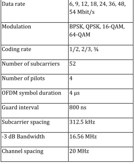
2. OFDM Parameters
© 2016, IRJET | Impact Factor value: 4.45 | ISO 9001:2008 Certified Journal
| Page 2291
Data rate 6, 9, 12, 18, 24, 36, 48,54 Mbit/s
Modulation BPSK, QPSK, 16-QAM, 64-QAM
Coding rate 1/2, 2/3, ¾
Number of subcarriers 52
Number of pilots 4
OFDM symbol duration 4 µs
Guard interval 800 ns
Subcarrier spacing 312.5 kHz
-3 dB Bandwidth 16.56 MHz
[image:2.595.39.264.100.373.2]Channel spacing 20 MHz
Table 1: Main Parameters of the OFDM standard.
In order to limit the relative amount of power and time spent on the guard time to 1 dB, the symbol duration was chosen to be 4 s. This also determined the subcarrier spacing to be 312.5 kHz, which is the inverse of the symbol duration minus the guard time. By using 48 data subcarriers, uncoded data rates of 12 to 72 Mbps can be achieved by using variable modulation types from BPSK to 64-QAM. In order to correct for subcarriers in deep fades, forward error correction across the subcarriers is used with variable coding rates, giving coded data rates from 6 up to 54 Mbps. Convolutional coding is used with the industry standard rate 1/2, constraint length 7 code with generator polynomials (133,171). Higher coding rates of 2/3 and 3/4 are obtained by puncturing the rate 1/2 code.
3. System Descrition
I.The block diagram of an OFDM system . The binary
information data are grouped and mapped into multi-amplitude-multi-phase signals. In this paper, we consider the 16-QAM modulation. After pilot insertion, the modulated data X(k) are sent to an IDFT and are transformed and multiplexed into x(n) as
II.
10
/ 2
)
(
)}
(
{
)
(
N
k
N kn j
e
k
X
k
X
IFFT
n
x
III. For n = 0, 1, 2, ...N-1
IV. where N is the number of subcarriers. The guard
interval Ng is inserted to prevent possible inter-symbol interference in OFDM systems, and the resultant samples xg
(n) are
V.
1
...
,...
1
,
0
1
...,
1
,
)
(
)
(
N
n
N
N
n
n
x
n
N
x
x
g g gVI. where Ng is the number of samples in the guard
interval. The transmitted signal is then sent to a frequency selective multipath fading channel. The received signal can be represented by
VII.
y
g(
n
)
x
g(
n
)
h
(
n
)
w
(
n
)
VIII.
IX. Where h(n) is the channel impulse response (CIR) and
w(n) is the Additive White Gaussian Noise (AWGN) and
is the circular convolution. The channel impulse response h(n) can be expressed as [17]X.
10
) ( 2
)
(
r
i
N n T f j
i
i Di
e
h
n
h
XI. Where r the total number of propagation paths, hi is
the complex impulse response of the ith path, fDi is the ith
path’s Doppler frequency shift which causes Inter channel Interference (ICI) of the received signals, τi is the delay
spread index, and i is the ith path delay time normalized by the sampling time. After removing the guard interval from yg(n), the received samples y(n) are sent to a Fast Fourier Transform (FFT) block to demultiplex the multi-carrier signals.
XII.
10
/ 2
)
(
1
)}
(
{
)
(
N
n
N kn j
e
n
y
N
n
y
FFT
k
Y
XIII. If we assume that the guard interval is longer than the
length of channe1 impulse response- there is no inter-symbol interference between OFDM symbols- the demultiplexed samples Y (k) can be represented by
XIV.
Y
(
k
)
X
(
k
)
H
(
k
)
W
(
k
),
k
0
,
1
,...
.
N
1
XV. Where
k N j T f
T f N n T f j
i
i Di
Di Di
e
e
h
k
H
2 ) sin( 2
)
(
and W(k)is
XVI. the Fourier transform of the AWGN w(k).
XVII. After that, the received pilot signals fYp(k)g are
extracted from fY (k)g, the channel transfer function fH(k)g can be obtained from the information carried by fHp(k)g. With the knowledge of the channel responses fH(k)g, the transmitted data samples fX(k)g can be recovered by simply dividing the received signal by the channel response:
XVIII.
)
(
ˆ
)
(
)
(
ˆ
k
H
k
y
k
© 2016, IRJET | Impact Factor value: 4.45 | ISO 9001:2008 Certified Journal
| Page 2292
XIX. where ^H (k) is an estimate of H(k) . After signal
demapping, the source binary information data are reconstructed at the receiver output.
XX. The OFDM transmission scheme makes it easy to
assign pilots in both time and frequency domain. two major types of pilot arrangement. The first kind of pilot arrangement shown it is denoted as block-type pilot arrangement. The pilot signal is assigned to a particular OFDM block, which is sent periodically in time domain. This type of pilot arrangement is especially suitable for slow-fading radio channels. The estimation of channel response is usually obtained by either LS or MMSE estimates of training pilots [5].
XXI. The second kind of pilot arrangement, is denoted as
comb-type pilot arrangement. The pilot signals are uniformly distributed within each OFDM block. Assuming that the payloads of pilot signals of the two arrangements are the same, the comb-type pilot assignment has a higher retransmission rate. Thus, the comb-type pilot arrangement system is provides better resistance to fast-fading channels. Since only some sub-carriers contain the pilot signal, the channel response of nonpilot subcarriers will be estimated by interpolating neighboring pilot sub-channels. Thus, the combtype pilot arrangement is sensitive to frequency selectivity when comparing to the block-type pilot arrangement system That is, the pilot spacing ( f)p, must be much smaller than the coherence bandwidth of the channel ( f)c [3].
4. Channel Estimation
For comb-type pilot sub-carrier arrangement, the Np pilot signals Xp(m) ;m = 0; 1; ...;Np - 1, are uniformly inserted into X(k). That is, the total N sub-carriers are divided into Np groups, each with L = N/Np adjacent sub-carriers. In each group, the first sub-carrier is used to transmit pilot signal. The OFDM signal modulated on the kth sub-carrier can be expressed as
1
...,
,
2
,
1
,
inf
0
)
(
)
(
)
(
L
l
data
ormation
l
m
X
l
mL
X
k
X
p Let T p p p p p pL
N
H
L
H
H
N
H
H
H
H
))]
1
)(
1
((
)...
1
(
)
0
(
[
)]
1
(
)...
1
(
)
0
(
[
be the channel response of pilot carriers, and
)]
1
(
)...
1
(
)
0
(
[
p p p pp
Y
Y
Y
N
Y
be a vector of received pilot signals. The received pilot signal vector Yp can be expressed as
p p p
p
X
H
W
Y
Where
1
)
(
...
0
0
.
.
.
.
...
)
1
(
.
.
.
0
....
0
)
0
(
p p p pN
X
X
X
where Wp is the vector of Gaussian noise in pilot sub-carriers.
A. LS Estimation
In conventional comb-type pilot based channel estimation methods, the estimation of pilot signals, is based on the LS method is given by
) 1 ( ) 1 ( ... ) 1 ( ) 1 ( ) 0 ( ) 0 ( )] 1 ( ... ) 1 ( ) 0 ( [ ˆ 1 , , , , p p p p p p p p p p p ls p ls p ls p ls p N X N Y X Y X Y Y X N H H H H
The LS estimate of Hp is susceptible to AWGN and Inter- Carrier Interference (ICI). Because the channel responses of data subcarriers are obtained by interpolating the channel characterstics of pilot subcarriers, the performance of OFDM systems which are based on comb-type pilot arrangement is highly dependent on the rigorousness of estimate of pilot signals. Thus, a estimate better than the LS estimate is required. The MMSE estimate has been shown to be better than the LS estimate for channel estimation in OFDM systems based on block-type pilot arrangement. The Mean Square Error (MSE) estimation, given in [17], shows that MMSE estimate has about 10-15 dB gain in SNR over the LS estimate for the same MSE values. The major drawback of the MMSE estimate is its high complexity, which grows exponentially with the observation samples.
B. MMSE Estimation
The MMSE estimator employs the second order statistics of the channel conditions in order to minimizes Mean Square Error (MSE). Let Rhh, RHH, and RYY be the autocovariance
matrix of h, H, and Y , respectively and RhY be the cross
covariance matrix between h and Y . Also σ2w denotes the AWGN variance E{|w2|}. Assume the channel vector h, and the
AWGN w are uncorrelated, it can be derived that [18]
H hh H
H
HH
E
HH
E
Fh
Fh
FR
F
R
{
}
{(
)(
)
}
© 2016, IRJET | Impact Factor value: 4.45 | ISO 9001:2008 Certified Journal
| Page 2293
) 1 )( 1 ( 0
) 1 (
) 1 ( 0 00
...
....
.
.
.
.
...
....
.
.
.
....
...
N N N N
N
N N N
TW
TW
TW
TW
And
N k i j k
i
N e
N TW, 1 2
is called as the twidle factor matrix. Assuming Rhh (thus RHH)
and σw2are known at the receiver in advance, the MMSE
estimator of the h is given
.
ˆ H
YY hY
MMSE R R YY
h
At last it can be estimated that
Hmmss=dshgfd
MMSE employs the second order statistics of the channel for estimation. Sometimes the channel statistics are not available, so it is difficult to estimate the channel in this situation. However, in OFDM systems the signal can be available at the receiver by means of pilot carriers.
Our Proposed Algorithm: 1. The Algorithm is as follows:
1) Initialize the observation weights wi = 1=n; i = 1;, 2,..., n.
2)For m = 1 to M.
a) Fit a classifier T(m)(x) to the training data using weights wi.
b) Compute
ni
n
i i i
m i i m
w
x
T
c
w
err
1 1
) ( )
(
/
))
(
(
||
c) Compute
)
1
log(
1
log
) (
) ( )
(
K
err
err
mm m
d) Set
)))
(
(
.
exp(
( ) ( )i m i m i
i
w
I
C
T
x
w
e) Re-normalize wi.
3) Output
)
)
(
(
max
arg
)
(
1
) ( ) (
k
x
T
I
x
C
M
m
m m
k
IV. SIMULATION RESULTS
The OFDM system channel estimation was simulated with LS, MMSE, BLUE and AdaBoost methods. In all simulations we have used QAM16 as the modulation scheme for the individual carriers. Other parameters of the simulation are given in the Table.I. Figure.3 shows comparison of Bit Error Rate (BER) for LS, MMSE, BLUE and AdaBoost. Figure.3 shows that the AdaBoost algorithm improves the performance specially in low SNR values. However, at high SNR both MMSE and AdaBoost show a similar performance. Furtheremore, AdaBoost gives better performance when compared to LS and BLUE. Nevertheless, BLUE and LS are performing same or we can tell BLUE gives very marginal improvement to LS.The reason for this performance increase is because of the covariance matrix used in the BLUE. As our noise is ASWGN and it has variance of 1 so the BLUE’s performance is all most that of LS algorithm.
V. CONCLUSION
© 2016, IRJET | Impact Factor value: 4.45 | ISO 9001:2008 Certified Journal
| Page 2294
renders the QAM mapping obsolete and thereby reducing thecomplexity of receiver designs.
REFERENCES
[1] G. Eason, B. Noble, and I.N. Sneddon, “On certain
integrals of Lipschitz-Hankel type involving products of Bessel functions,” Phil. Trans. Roy. Soc. London, vol. A247, pp. 529-551, April 1955. (references)
[2] J. Clerk Maxwell, A Treatise on Electricity and
Magnetism, 3rd ed., vol. 2. Oxford: Clarendon, 1892, pp.68-73.
[3] I.S. Jacobs and C.P. Bean, “Fine particles, thin films and
exchange anisotropy,” in Magnetism, vol. III, G.T. Rado and H. Suhl, Eds. New York: Academic, 1963, pp. 271-350.
[4] K. Elissa, “Title of paper if known,” unpublished. [5] R. Nicole, “Title of paper with only first word
capitalized,” J. Name Stand. Abbrev., in press.
[6] Y. Yorozu, M. Hirano, K. Oka, and Y. Tagawa, “Electron
spectroscopy studies on magneto-optical media and plastic substrate interface,” IEEE Transl. J. Magn. Japan, vol. 2, pp. 740-741, August 1987 [Digests 9th Annual Conf. Magnetics Japan, p. 301, 1982].
[7] M. Young, The Technical Writer’s Handbook. Mill Valley,