Journal of Chemical and Pharmaceutical Research, 2013, 5(12):859-864
Research Article
CODEN(USA) : JCPRC5
ISSN : 0975-7384
Micro electrical discharge machining single discharge temperature
field simulation
1,2
Z.L.Peng*,
1Y.N.Li,
1D.Fang and
1Y.Y.Zhang
1
School of Mechanical Engineering, Qingdao Technological University, Qingdao, China
2College of Electromechanical Engineering, China University of Petroleum, Qingdao, China
_____________________________________________________________________________________________
ABSTRACT
A single discharge temperature field simulation in micro electrical discharge machining (micro EDM) using finite element method is introduced, which mainly influences the materials removal of electrodes. With given process parameters, the materials removal amount of both tool electrode and work piece in single discharge were calculated considering heat source model, energy distribution and boundary conditions. The influences of process parameters on the material removal amount of anode and cathode respectively have been researched and discussed under the analysis of simulation results. Results show that the discharge current has more degree of influence on material removal amount than the discharge on-time is. Meanwhile, with the discharge current increases, the difference of material removal amount between anode and cathode in micro EDM enlarges. From the simulation results, it is interestingly found that the influences of material removal amount against discharge on-time are not the same as the discharge current. With the discharge on-time increases, the material removal amount of both the electrodes increases, but the difference of the removal amount between the anode and cathode has a maximum value at the discharge on-time of 8µs. The simulation results are helpful to select machining parameters in the discharge experiments for good machining performance.
Key words: micro EDM, single discharge, temperature field simulation
_____________________________________________________________________________________________
INTRODUCTION
Recent years, micro electro-mechanical system (MEMS) has been increasingly with the development of science and technology. The practical application of MEMS eventually relies on precision manufacturing technology with the features of high precision and high stability of small device or components [1-4]. As the machining dimension reducing, the traditional machining method has shown vain to meet the latest requirements in some cases. The micro machining technology needs to transform from traditional silicon material to the superior performance alloy materials, from traditional separation processing to integrate processing by various processing methods.
The research of new micro machining method for metal micro parts fabrication in the micron or nanometer scale with three-dimensional processing capacity becomes urgent increasingly. It is well known that micro EDM has been widely used in the field of micro machining of electrical conductive material. When a discharge occurred between the tool electrode and the work piece, a little amount materials will be removed from both electrodes under the discharge energy. As the advantages of non-contact machining, discharge energy easy to be controlled, electro-thermal removal process and so on [5,6], micro EDM is now successfully used in micro machining of hard-to-cut materials, micro holes and micro three-dimensional metal structures.
deposition process [7]. And now we can see that researching the removal amount of anode and cathode respectively in single discharge has the beneficial to understanding the discharge feature in micro EDM.
It is difficult to observe or measure the discharge course as the discharge stochastic nature in micro EDM and little discharge distance. The material migration process in discharge has not form an undisputed explain.
Numerous numerical simulation method have been tried to reveal the physical essence of discharging itself and many beneficial results have been obtained [8-11]. It is shown that different heat sources including point heat source, and circular heat source, Gaussian heat source and so on has been used in simulation and hoped to get close to the actual discharge. However, it is not easy to obtain a uniform simulation model to explain the discharge features in micro EDM.
In this paper, a single discharge temperature field simulation in micro EDM using finite element method is introduced. From the view point of temperature field, the materials removal amount on both anode and cathode in single discharge will be researched. With given process parameters, the materials removal amount of both tool electrode and workpiece in single discharge were calculated considering heat source model, energy distribution and boundary conditions. The removal amount of materials from electrodes in simulation is assumed the areas where temperature exceeds the electrode material molten point. Then the material removal amount of anode and cathode can be calculated with different discharge parameters. We believed that this research of the maximum difference of removal amount between electrodes in single discharge will be a valuable point for selecting discharge polarity and optimizing discharge parameters. It is also beneficial to understanding the intrinsic of material migration process in both micro EDM removal and micro EDM deposition process.
SINGLE DISCHARGE TEMPERATURE FIELD SIMULATIONS Relations of simulation with discharge parameters
The purpose of this research is to establish the relation of simulation results and micro EDM discharge experiments. The removal amount of anode and cathode in single discharge can be calculated. The maximum removal difference between the electrodes can be obtained. In order to obtain the best machining performance, in micro EDM removal process, we can select the polarity to reduce the tool electrode wear, and we can select high level of tool wear to achieve micro EDM deposition process also.
[image:2.595.125.498.596.754.2]In micro EDM, when the distance between the electrodes is so small that the electric field force exceeds the insulation strength of the dielectric, cathode surface will emit a mass of electrons under the action of electric field force. The emitted electrons will be accelerated and moved to the anode and ions move to cathode. In this course, the high speed particles motion will collide with the dielectric medium particles, so that electric particles increase tempestuously to form a plasma discharge channel and generate a large amount of heat. Both anode and cathode will be melt or gasify a small amount. Then with the voltage drops into the pulse interval, single discharge terminate.
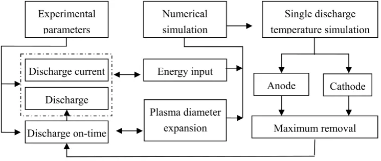
Fig. 1 shows the relations of experimental discharge parameters with the numerical simulation results. The values of the discharge current, discharge on-time and discharge voltage in experimental parameters correspond to the energy input in the simulation. As the discharge voltage is usually sustained at a constant, the discharge current and discharge on-time are more important to influence the energy input. The discharge on-time can also be decided by the plasma diameter expansion, which expresses the heat source load area. The simulation results of maximum removal amount difference can be calculated and the value can be feed back to the experimental parameters to obtain the optimal machining performance.
Fig. 1 Relations of simulation with discharge parameters Experimental
parameters
Discharge Discharge current
Discharge on-time
Single discharge temperature simulation
Anode Cathode
Maximum removal Numerical
simulation
Energy input
Simulation process
Heat source model: In micro EDM, the thermal effect is closely related to the material removal process. A large
[image:3.595.223.391.191.297.2]portion of released energy by discharge forming a high temperature heat source transmits to the tool electrode and the workpiece. The surface heat source plays a major role on the material removal of electrodes. The surface source on the electrode is not displayed uniform as the discharge channel characteristics. The effect of heat flux density in the surface source will show as Gauss distribution, which is a normal heat source model adopted in the plasma numerical simulation. And the Gauss heat source has the better consistence with the particles distribution in discharge channel. Fig. 2 shows the Gauss heat source distribution. The particle density is highest in the center, lowest at discharge channel edge and zero at the point where heat flux density is lower than 0.05qm.
Fig. 2 Gauss heat source model
The Gauss heat source formula is shown as following relations:
)
exp(
kr
2q
q(r)
=
m−
(1)
Where, q is the heat flux density at the radius of r (W/m2); qm is the maximum of heat flux density (W/m2); k is the coefficient of concentration.
Then we define Q is the energy input on the Gauss heat source distribution area, U is the discharge voltage, I is the discharge current, η is the energy distribution factor. qm can be expressed as followed.
UI t R Q k
qm
η
π
π
()3 2
=
= (2)
Combine with formula (1), we can obtain the heat flux density on the discharge channel.
)
)
(
3
exp(
)
(
3
)
(
2 22
R
t
r
ηUI
t
R
r
q
=
−
π
(3)It can be seen from equation (3) that the heat flux density is related with the discharge current, discharge on-time, energy distribution ratio and heat flux load area.
Energy distribution ratio: As the polarity effect of EDM, the energy distribution into anode is not the same as
cathode. The energy distribution factor η is key factor to influent the material removal amount of electrodes. Many studies have been acted to determine the value in given conditions. Hayakawa et al. [12] reported that the energy distributed into work piece was nearly 50%. Xia et al [13] believed that the energy distributed ratio to anode and cathode was about 40% and 25%, respectively. From the former researches, we can see that energy distribution is higher on the anode than that of cathode. And almost all the discharge energy is conducted into the electrodes, the heat dissipated by convection and radiation can be negligible in the micro EDM process. In this study, the energy distribution factor is selected 0.5 to anode and 0.25 to cathode.
Heat source load area: The diameter of discharge channel between electrodes is the area of heat source load in
Considering the unique characteristics of micro EDM process, the discharge parameters should be selected the lower value including discharge current and discharge on-time to ensure the micro energy obtained. In order to enlarge the removal amount between anode and cathode, narrow discharge on-time should be used.
Boundary Conditions and meshed model: In this simulation, a Fourier heat conduction equation is established
and the boundary conditions are determined under the several suppositions.
The initial temperatures of electrodes T=T0=298 Kelvin. The external areas of electrodes discharge surface are supposing insulated. The heat convection mode is used, which is expressed as
q=h (TS−TB) (4)
Where, h is the heat convection coefficient, TS electrodes surface temperature (K) and TB is medium temperature (K).
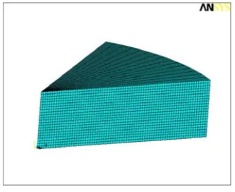
In order to guarantee the accuracy of the calculation and the less computing time in simulation, 1/8 research area of discharge point and non uniform mesh model has been used. The mesh model is shown in Fig. 3.
Fig. 3 1/8 discharge point and non uniform mesh model
RESULTS AND DISCUSSION
Results of material removal with discharge on-time
In simulation, the discharge current was set as 4A, and the discharge on-time was set as 2µs, 4µs, 8µs and 16µs respectively. The energy distribution factor η was set as 25% for cathode and 50% for anode. We believe that the material removed amount in single discharge is the volume where temperature is higher than the material melt point. And the simulation results are shown in Fig. 4 using discharge current 4A, discharge on-time 2µs.
[image:4.595.223.390.283.419.2]a) b)
[image:4.595.161.460.561.678.2]Repeating the similar simulation process, we can obtain the removed volume on anode and cathode of single discharge under rest discharge on-time, and the results are shown in Figure 5.
[image:5.595.208.406.111.258.2]Fig. 5. Removed volume with discharge on-time
Figure 5 show that the removal volume of anode, cathode and the volume difference under the different discharge on-time of 2µs, 4µs, 8µs and 16µs and the discharge current set 4A. We can see that with the discharge on-time increases, the removed volume (melted material) increases both anode and cathode. It is interesting that there is a peak value of removal volume difference at about 8µs of discharge on-time. It is helped to select discharge parameters for obtaining the maximum removal difference between tool electrode and work piece.
Results of material removal with discharge current
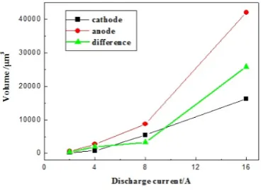
In this process, the discharge on-time was set at 4A, and the discharge current was set at 2A, 4A, 8A and 16A respectively. The energy distribution factor η was set as 25% for cathode and 50% for anode according to the analysis of above. And we can obtain the removed volume on anode and cathode of single discharge under different discharge current. The simulation results are shown in Fig. 6.
Figure 6. Removed volume with discharge current
From the figure we can see that with the discharge current increases, the removed volume (melted material) increases both anode and cathode. There is not a peak value in the difference curve of the two electrodes. But when the discharge current exceed the value of 8A, the removed volume of electrodes and the removal volume difference are all increased extremely. So in discharge experiments, we can enlarge the discharge current to increase the removal volume difference between tool electrode and workpiece.
CONCLUSION
In this paper, a single discharge thermal simulation of anode and cathode are researched, and the removal volumes of anode and cathode in single discharge under different discharge energy are analyzed. The following conclusions are drawn.
[image:5.595.211.397.441.575.2](2) The influence of material removal amount by discharge current is higher that of the discharge on time. The higher the discharge current is, the larger the removal volume difference in single discharge between anode and cathode is.
(3) Simulation results show that there is a peak value of removal volume difference between anode and cathode at discharge on-time with 8µs. It is helped to determin discharge parameters range for the experiments.
Acknowledgements
This research was supported by National Natural Science Foundation of China (51105217), China Postdoctoral Science Foundation (2012M511556), Special Funds for Postdoctoral Innovative Projects of Shandong Province (201202039), and Qingdao Municipality Planning Project of Science and Technology (13-1-4-167-jch).
REFERENCES
[1] E. Brinksmeier, R. Gläbe, O. Riemer, S. Twardy. Microsyst Technol. 2008 (14): 1983-1987.
[2] H. S. Liu, B. H. Yan, C. L. Chen, F. Y. Huang. Int J Mach Tools Manuf.2006 (46):80-87.
[3] M. Geiger, M. Kleiner, R. Eckstein, N. Tiesler, U. Engel. CIRP Ann Manuf Technol.2001 (50): 445–462.
[4] C.H. Li, Y.L. Hou, Z.R. Liu, Y.C. Ding. Int. J. Abras. Technol. 2011 (4):77-89.
[5] M. P. Jahan, Y. S. Wong, M. Rahman. J Mater Process Technol. 2009 (209):1706-1716.
[6] F. Vollertsen, Z. Hu, H.S. Niwhoff, C. Theiler. J Mater Process Technol. 2004 (1-3):70-79.
[7] Z.L.Peng, Z.L.Wang, Y.H.Dong, H.Chen. J Mater Process Technol.2010 (210):129-136.
[8] S. N. Joshi, S. S. Pande. Appl. Soft Comput. J.2011 (11): 2743–2755.
[9] P. Allen, X. Chen. J Mater Process Technol.2007 (186): 346–355.
[10] X.D.Yang, J.W.Guo,X.F.Chen. Precis Eng. 2011 (35):51-57.
[11] M. Zahiruddin, M. Kunieda. CIRP Ann Manuf Technol.2012 (61): 187–190.
[12] S. Hayakawa, M. Yuzawa, M. Kunieda, N. Nishiwaki. IJEM.2001 (6):19-26.
[13] H. Xia, M. Kunieda, N. Nishiwaki. IJEM. 1996 (1): 45-52.