OPTICAL INJECTION PHASE-LOCK
LOOPS
by
ALDARIO CHRESTANIBORDONALLI
Submitted to the University of London in fulfilment of the requirements for the degree of Doctor of Philosophy
Supervised by Professor A. J. Seeds
Department of Electronic and Electrical Engineering University College London
Torrington Place, London, W C IE 7JE
All rights reserved
INFORMATION TO ALL USERS
The quality of this reproduction is dependent upon the quality of the copy submitted. In the unlikely event that the author did not send a complete manuscript and there are missing pages, these will be noted. Also, if material had to be removed,
a note will indicate the deletion.
uest.
ProQuest 10017161
Published by ProQuest LLC(2016). Copyright of the Dissertation is held by the Author. All rights reserved.
This work is protected against unauthorized copying under Title 17, United States Code. Microform Edition © ProQuest LLC.
ProQuest LLC
789 East Eisenhower Parkway P.O. Box 1346
Abstract
Optical Injection Phase-Lock Loops
Locking techniques have been widely applied for frequency synchronisation of semiconductor lasers used in coherent communication and microwave signal generation systems. Two main locking techniques, the optical phase-lock loop (OPLL) and optical injection locking (OIL) are analysed in this thesis. The principal limitations on OPLL perform ance result from the loop propagation delay, which makes difficult the implem entation o f high gain and wide bandwidth loops, leading to poor phase noise suppression perform ance and requiring the linewidths o f the sem iconductor laser sources to be less than a few megahertz for practical values of loop delay. The OIL phase noise suppression is controlled by the injected power. The principal limitations of the OIL implem entation are the finite phase error under locked conditions and the narrow stable locking range the system provides at injected power levels required to reduce the phase noise output of semiconductor lasers significantly.
my mother Marlene
Acknowledgements
My sincere thanks to Professor Alwyn J. Seeds for his expert supervision, for his support and counselling throughout the work and for his patience and dedication in reading and commenting upon the contents of this thesis.
Also, I would like to thank Dr. D. W ake (BT Research Laboratories), for supplying the lasers, and many staff and students at UCL, particularly the clean room and workshop staff, for their advice and assistance.
I wish to express my friendship and acknowledgement to all my fellow students, staff and ex-staff of the Microwave Opto-Electronics Group: B. Cai, D. Atkinson, St. J. Hoskyns, X. Huang, C. P. Liu and, in particular, C. Walton, who helped me with the electronics design. They have brought many useful ideas and com m ents to the development of this work.
I would like to acknowledge the support and encouragement from all my family and friends, particularly Lilian, my wife, David, Peter and Victor.
Introduction
24
1 .1 - Locking Techniques 24
1.1.1 - The Optical Phase-Lock Loop 25
1.1.2 - Optical Injection Locking 28
1.2 - The Optical Injection Phase-Lock Loop 29
1.3 - OIPLL Applications 32
1.4 - Structure of the Thesis 33
References 34
Chapter 2:
Optical Phase-Lock Loop Theory
40
2.1 - Block Diagram and Transfer Functions 40
2.1.1 - Time Domain Analysis 40
2.1.2 - Frequency Domain Analysis 44
2.2 - Loop Filters and Stability 46
2.2.1 - First Order Loop 47
2.2.2 - Modified First Order Loop 50
2.2.3 - Second Order Type II Loop 53
2.3 - Noise Sources for OPLLs 57
2.4 - Conclusions 59
References 60
Chapter 3\
Optical Injection Locking Theory
62
3.1 - Block Diagram and System Equations 62
3.1.1 - Time Domain Analysis 62
3.1.2 - Frequency Domain Analysis 69
3.2 - Phase-Lock Loop Model for Injection Locking 71
3.3 - Noise Analysis 74
3.4 - Conclusions 74
References 76
Chapter 4:
Optical Injection Phase-Lock Loop Theory
78
4.1 - Block Diagram and Transfer Functions 79
4.1.1 - Time Domain Analysis 79
4.1.2 - Frequency Domain Analysis 81
4.2 - Loop Filters and Stability 82
4.2.1 7 First Order Loop 82
4.2.2 - Modified First Order Loop 84
4.2.3 - Second Order Type II Loop 86
4.3 - Noise Sources for OIPLLs 88
4.4 - Locking Technique Performance 90
4.4.1 - Phase Error and Noise Sources 90
4.4.1.1 - Laser Phase Noise 91
4.4.1.2 - Detector Shot Noise 93
4.4.2 - OPLL Performance 94
4.4.3 - OIL Performance 102
4.4.4 - OIPLL Performance 106
4.5 - Differential Phase Effects on OIPLL Systems 110
4.6 - Conclusions 115
References 117
Chapter 5:
Optical and Electrical Design
120
5.1 - Experimental Arrangement 120
5 .1 ,2 - Path Matching Correction 125
5.2 - Semiconductor Lasers 127
5.2.1 - General Characteristics 128
5.2.2 - Tuning Characteristics 135
5.3 - Opto-Electronic Receiver Design 145
5.4 - Loop Electronics Design 150
5.5 - Effect o f Real Loop Filter Response 157
5.6 - Conclusions 158
References 160
Chapter 6:
Experimental Results
162
6.1 - The OIPLL Experimental Arrangement 162
6.2 - The OPLL Experiment 165
6.3 - The OIL Experiment 172
6.3.1 - Injection Ratio Calibration 173
6.3.2 - OIL Phase Noise Suppression 179
6.4 - The OIPLL Experiment 182
6.5 - Conclusions 187
References 188
Chapter
7: Conclusions
190
7.1 - Main Results 190
7.1.1 - OIPLL Theory 190
7.1.2 - OIPLL Experiment 191
7.2 - Discussion 192
7.3 - Suggestion for Future Work 193
7.3.1 - Implementation of Heterodyne OIPLLs 194
7.3.2 - Implementation of the System in OEIC Form 194
7.3.3 - Completing the Study of OIPLL Performance 196
References 196
Appendix
A: Heterodyne Photodetection
200
Appendix B:
Laser Electric Field and Associated Photon Number
202
References 203
Appendix C:
Detector Shot Noise
204
References 205
Appendix
D: Passive Optical Components
206
D .l - The Polarising and Neutral Beam Splitters 206
D.2 - H alf and Quarter-Wave Plates 207
D.3 - The Isolator 209
References 210
Appendix E:
Delayed Self-Homodyne Technique
211
References 217
Appendix F:
Hi-Bi Mach-Zehnder Interferometer
218
A amplifier gain
a fibre losses in the fibre path a o f the DSHT
Acr photodetector cross-section area (m^)
AFC automatic frequency control
AlGaAs aluminium gallium arsenide
AM amplitude modulation
AMP amplifier
Ap photodetector illuminated active area (m^)
Ar offset generator signal amplitude (V)
ATT attenuation
b fibre losses in the fibre path b of the DSHT
BS beam splitter
C coupler
c velocity of light (m/s)
CFIS collimating, focusing and isolating fibre-pigtailed system
C O2 carbon dioxide
CR fibre chuck rotator
D diffusion coeficient (m^/s)
d laser active area thickness (m), distance into photodetector (m)
DFB distributed feedback
DS detection system
DSHT delayed self-homodyne technique
e electron charge (C), exponential symbol
E(s) error transfer function
E(t) laser complex emission field (V/m)
Ely laser 1 electric field in the y direction (V/m)
E2y laser 2 electric field in the y direction (V/m)
E a ( t ) electric field travelling the fibre arm a in the DSHT (V/m)
Ea(t) laser a electric field (V/m)
Eao laser a electric field amplitude (V/m)
Eb(t) electric field travelling the fibre arm b in the DSHT (V/m)
Eb(t) laser b electric field (V/m)
Ebo laser b electric field amplitude (V/m)
Ec(s) OIPLL error transfer function
Efhd(t) fast axis electric field component in the H delayed axis direction (V/m) Efhp(t) fast axis electric field component in the H principal axis direction (V/m)
Efout(t) HBF fast axis output electric field (V/m)
Efqd(t) fast axis electric field component in the Q delayed axis direction (V/m)
E f q p ( t ) fast axis electric field component in the Q principal axis direction (V/m)
Efr(t) fast axis electric field component reflected by the PBS (V/m)
Eft(t) fast axis electric field component transmitted by the PBS (V/m)
Em(t) master laser electric field (V/m)
Emo master laser electric field amplitude (V/m)
Eo laser field amplitude (V/m)
Eo(t) modulated complex electric field (V/m)
Eout(t) total electric field at DSHT fibre output (V/m)
Er(t) total PBS reflected electric field (V/m)
Es(t) slave laser electric field, HBF slow axis electric field (V/m)
Eshd(t) slow axis electric field component in the H delayed axis direction (V/m)
Eshp(0 slow axis electric field component in the H principal axis direction (V/m)
Eso slave laser electric field amplitude (V/m)
Es out(t) HBF slow axis output electric field (V/m)
Esqd(t) slow axis electric field component in the Q delayed axis direction (V/m)
Esqp(t) slow axis electric field component in the Q principal axis direction (V/m)
Esr(t) slow axis electric field component reflected by the PBS (V/m)
Est(t) slow axis electric field component transmitted by the PBS (V/m)
Et(t) total PBS transmitted electric field (V/m)
Etot(t) total electric field of the beam reaching the photodetector active area (V/m)
F(s) loop filter transfer function
f(t) loop filter impulse response
FC 3 dB fibre coupler
fc modified first order loop filter cut-off frequency (Hz)
FCC focusing and collimating pigtailed fibre
F^ phase Langevin noise term (s O
F^(s) Laplace transform of F^
Fftn(s) slave laser modulation response transfer function
ffm(t) impulse response of the laser FM response
Fi photon number Langevin noise term (s ^)
Fj(s) Laplace transform of Fj
FM frequency modulation
F n ( s ) Laplace transform of F „
f p & a ( 0 impulse response of the photodetector and amplifier
fpd(t) phase detector impulse response
FPI Fabry-Perot interferometer
fr laser resonance frequency (Hz)
FSR free spectral range (Hz)
FWHM full width half maximum
G(s) open loop transfer function
G(t) laser complex gain (s‘0
GaAs gallium arsenide
Gc(s) OIPLL open loop transfer function
Gcd(s) OIPLL open loop transfer function considering differential phase
Gi photon number differential gain (s ’)
Gn carrier number differential gain (s ’)
Go free-running laser gain (s ’)
H half-wave plate
h Planck constant (Is)
h
Planck constant /2n
(Is)H(s) closed loop transfer function
HBF hi-bi fibre
Hc(s) OIPLL closed loop transfer function
Hcd(s) OIPLL closed loop transfer function considering differential phase
HeNe helium neon
Hoil(s) injection locking transfer function
I laser pumping current (A)
Ï average photocurrent (A)
I(t) number of photons
i(t) photocurrent due to E,o,(t) (DSHT) (A)
i a ( t ) loop photodetector output current (A)
ib(t) current after phase detector (A)
i c ( t ) current after loop filter (A)
im(s) Laplace transform of îm(t)
îm(t) deviation from the steady state value for 1^(1)
Im(t) master laser photon number
Imo Steady state value for 1^(1)
io amplitude of i,i(t) and 1,2(1) (A), amplitude of i(t) (DSHT) (A)
ior photocurrent amplitude due to the reflected PBS beam after HBF (A)
iot photocurrent amplitude due to the transmitted PBS beam after HBF (A)
i r ( t ) photocurrent due to the reflected PBS beam after HBF (A)
iref network analyser reference signal (A)
î s ( s ) Laplace transform of îj(t)
î s ( t ) deviation from the steady state value for Ij(t)
Is(t) slave laser photon number
ISO isolator
Î50 non-injection photon number steady state value
Iso steady state value for 1,(1)
1^(1) current produced by a photodetector in a period T (A)
i,(t) photocurrent due to the transmitted PBS beam after HBF (A)
It(co) Fourier transform of iy(t)
i,i(t) transmitted PBS photocurrent for 2n7C+7t/2 operating points (A) i,2(t) transmitted PBS photocurrent for 2n7t+37c/2 operating points (A)
I,h laser threshold current (A)
J carrier injection density (A/m^)
k loop gain (s ')
kamp gain of the loop first stage amplifier
kco coupling efficiency
kco-isa LSA coupling efficiency
kcr, (Ak)cr critical loop gain (s ^
kd phase detector gain factor (V/rad)
kd' defined as kd/Ri2 (V/rad)
km phase detector constant
ko slave laser gain factor (Hz/A)
kj intensity modulation index
koiL injection locking gain term (s ’)
k'pd effective photodetector gain factor (A/rad)
kpd photodetector gain factor (A/rad)
kpd-isa LSA photodetector gain factor (A/rad)
kv loop DC gain (s ’)
1 HBF length (m)
L lens, slave laser effective cavity length (m), photodetector side length (m)
L(s) determinant of the OIL process matrix
LiNbOa lithium niobate
Lm FPI mirror distance (m)
LSA lightwave signal analyser
LUT laser under test
m integer number
M mirror
m(t) electric field modulation function
M L master laser
M OD modulator
n material refractive index, integer number
h(s) Laplace transform of n(t)
No free running steady state carrier number
N'(s) Laplace transform of n'(t)
N(t) carrier number
n'(t) quadrature representation of the additive photodetection noise
n (t) deviation from the steady state value for N(t)
n(t) photodetection additive noise (A)
NApMCfm) laser FM response obtained from network analyser
NA,i(C0m) network analyser measurement using iti(t) NA,2(C0m) network analyser measurement using it2(t)
NBS neutral beam splitter
UcCt) laser carrier density (m-^)
nf HBF fast axis refractive index
ng group refractive index
No steady state value for N(t)
Hphoton photon density (m-^)
ns HBF slow axis refractive index
Nt total number of events occuring within T
Ny average number of events within T
OEIC(s) opto-electronic integrated circuit(s)
OIL optical injection locking
OIPLL(s) optical injection phase-lock loop(s)
OPLL(s) optical phase-lock loop(s)
P polariser, total power coupled into photodetector (W)
Pa laser a optical power coupled into the photodetector (W)
Pb laser b optical power coupled into the photodetector (W)
PBS polarising beam splitter
PC polarisation controller
Pd c(k) average dissipated power due to the DC photocurrent (W)
p^^(A(|)) phase difference probability density function
PH photodetector
Pin total power coupled into the spectrum analyser (W)
Pm detected master laser optical power (W)
Pmo master laser injected optical power (W)
PMPh power meter photodetector
Ps detected slave laser optical power (W)
Pso slave laser optical power (W)
Q quarter-wave plate
r photodetector load resistance (12)
R photodetector responsivity (AAV), spontaneous emission rate (s ’)
RBW resolution bandwidth (Hz)
RC resistor-capacitor
Ri(t) photocurrent autocorrelation function (A^)
Rii amplifier input impedance (Q)
Ri2 loop filter input impedance (Q)
Rioad spectrum analyser input impedance (12)
Rioss carrier loss (m-^s ’)
S(f) measured power spectral density (W/Hz)
Sbeat(f) beat signal power spectral density (W/Hz)
SENS sensitivity
S(|,(f) phase error spectrum related to measured power spectral density (rad^/Hz)
SpM(f) FM noise spectral density (Hz^/Hz)
Si(f) power spectral density due to photocurrent (W/Hz)
SL slave laser
S,(f) laser spectral density (W/Hz)
So maximum intensity for the DSHT measurement (W/Hz)
So il(F ) OIL phase error spectrum (rad^/Hz)
SoiPLL(f) OIPLL phase error spectral density (rad^/Hz)
S oiP L L -d(f) OIPLL phase error spectral density considering differential phase (rad^/Hz)
SopLL(f) OPLL phase error spectral density (rad^/Hz)
SpN(f) phase noise spectral density (rad^/Hz)
SpN-ML(f) master laser phase noise spectral density (rad^/Hz) SpN-sL(f) slave laser phase noise spectral density (rad^/Hz)
Ssh(f) DSHT power spectral density due to the laser phase noise (W/Hz)
Ssn(f) shot noise power spectral density (A^/Hz)
SsnCO shot noise translated phase noise power spectral density (rad^/Hz)
ST sweep time (s)
T delay between the fibre arms of the DSHT (s), period of time (s)
ta time interval for light travelling the master laser-photodetector path (s)
tb time interval for light travelling the injection path (s)
tc time interval for light travelling the slave laser-photodetector path (s)
Tes average time between cycle slips (s)
td delay between reference and test signals for the network analyser (s)
Td loop propagation delay (s)
tf HBF fast axis time interval (s)
To average delay between the two HBF axis (s)
ts HBF slow axis time interval (s)
TS translation system
u(t) representation of the current resulting from a single electron generation
U(t) total energy (J)
U(co) Fourier transform of u(t)
V single carrier drift velocity (m/s)
Va(t) signal coupled into the phase detector after the amplifier (V)
VB video bandwidth (Hz)
Vb(t) signal after the phase detector (V)
Vg group velocity (m/s)
Vr(t) offset generator signal (V)
W G wave-guide
x(t) complex wave function
XeF xenon fluoride
z characteristic impedance of the medium
(Q.)
a
linewidth enhancement factor ( a factor)P frequency modulation index
Ô path mismatch phase term (rad), constant defined as tan i(a )
Aô phase shift due to the delay between HBF axes (rad)
Ad wavefront mismatch (m)
Af, AfpwHM FWHM laser linewidth (Hz)
Affm peak frequency deviation (Hz)
Afmeas linewidth measured by the DSHT (Hz)
Afmi master laser FWHM laser linewidth (Hz)
Afms FWHM master and slave laser summed linewidths (Hz)
Afsi slave laser FWHM laser linewidth (Hz)
AfsT laser linewidth due to spontaneous emission (Hz)
AG steady state gain (s-*)
ANq steady state carrier number
At delay between the HBF axis coupled electric fields after length 1 (s)
AV laser active area volume (m^)
Aco OIL locking bandwidth (rad/s)
AcOfr detuning when the photon number equals the free-running value (rad/s)
AcOh hold-in range (rad/s)
AcOhoiL injection locking hold-in range (rad/s)
AcOhi OIL half locking bandwidth (rad/s)
AcOi lock-in range (rad/s)
AcOms defined as IttAf^g (rad/s)
AcOpi pull-in limit (rad/s)
AcOpo pull-out range (rad/s)
Eo vacuum permittivity (F/m)
Ef material permittivity (F/m)
(t)(t) laser phase (rad)
0 (t) optical intensity (W/m^)
0 ] (t) laser 1 average optical intensity (W/m^)
0 2(1) laser 2 average optical intensity (W/m^)
0max maximum optical intensity (W/m^)
(|)a(t) laser a phase (rad)
(|)b(t) laser b phase (rad)
(|)m(s) Laplace transform of
^^{i)
(|)m(t) master laser phase (rad)
(|)mo Steady state value of (j)o,(t)
<t>ms(t) phase error after the photodetector (rad)
0 0 average laser intensity in the DSHT (W/m^)
# )
<|).(s)
4)»o % Y^'(T)r “'(t„t2)
r„(s)
Ym(t)r,(s)
Y(t) j-«(2m) n 9 K A 1^00
8(s)
0 (t) 8(t)8 d i f f
00
0o i l(s)
0OIPLl(s)
0o p l l(s)
A(|> 2 OIL 2 OIPLL 2 OIPLL-d
offset generator phase (rad) Laplace transform of (|)g(t) slave laser phase (rad) steady state value of (|)s(t)
laser 1 and 2 total optical intensity (W/m^) laser damping constant
second order laser emission field coherence function laser emission field complex degree of coherence second order phase coherence function
Laplace transform of Ym(t)
deviation from the steady state value for Laplace transform of Ys(t)
deviation from the steady state value for (|)g(t)
2mth-order coherence function of a complex wave x(t)
normalised second order coherence function injection coupling efficiency
frequency modulation phase (rad) wavefront mismatch angle (deg)
proportionality constant of DSHT theory material permeability (H/m)
vaccum permeability (H/m)
discrimination response correction phase term (rad) Laplace transform of 0(t)
phase error at the phase detector or photodetector output (rad) deviation from the steady state value for 0(t)
differential phase (rad or deg) steady state value for 0(t) OIL phase error (rad) OIPLL phase error (rad) OPLL phase error (rad) injection locking rate (s ') phase error variance (rad^) phase difference variance (rad^) OIL phase error variance (rad-) OIPLL phase error variance (rad^)
^OPLL OPLL phase error variance (rad^)
T modified first order filter time constant (s)
Ti,T2 second order filter time constant (s)
Tc laser coherence time (s)
Td photodetector electron transit time (s)
Ti laser round trip time (s)
Tp laser photon life time (s)
Ts laser carrier life time (s)
cOa laser a angular frequency (rad/s)
0)b laser b angular frequency (rad/s)
cOcr critical angular frequency for loop stability (rad/s)
cOm ML angular frequency (rad/s), angular modulation frequency (rad/s)
cOms laser heterodyne beat angular frequency (rad/s)
oOno zero delay natural frequency (rad/s)
(Do laser angular frequency (rad/s)
(Dr offset generator signal angular frequency (rad/s)
CDs SL angular frequency (rad/s)
Ç magnitude of the laser flicker noise (Hz^)
^0 zero delay damping ratio
Chapter 1:
Fig. 1.1 - General block diagram of an OPLL system. Fig. 1.2 - General injection locking experiment. Fig. 1.3 - General block diagram of an OIPLL.
Chapter 2:
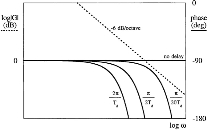
Fig. 2.1 - The heterodyne optical phase-lock loop. Fig. 2.2- Bode plot of G(s) for a first order loop.
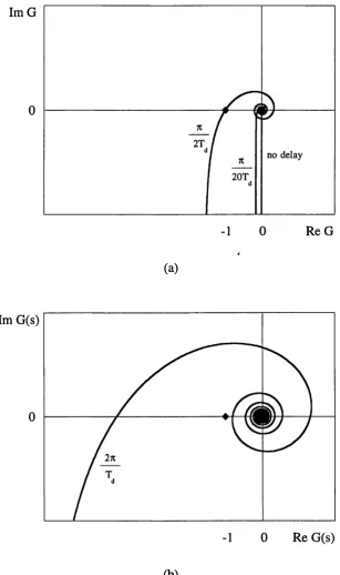
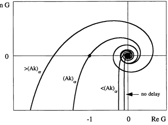
Fig. 2.3 - Nyquist plots of G(s) for a first order loop, (a) zero delay system and increasing values of Ak. (b) Ak beyond critical.
Fig. 2.4 - Bode plot for a modified first order loop. Fig. 2.5 - Nyquist plot for a modified first order loop. Fig. 2.6 - Bode plot for a second order loop.
Fig. 2.7 - Nyquist plot for a second order loop.
Chapter 3:
Fig. 3.1 - Block Diagram of an optical injection locking system.
Fig. 3.2 - Locking characteristics for a DFB laser (1550 nm, InP/InGaAsP, second order grating, length 322 p.m, effective refractive index 3.23, K factor 23/cm, facet reflections 0.2% and 30% , linewidth enhancement factor 5.4 and internal loss 50/cm).
Fig. 3.3 - Block diagram of the injection locking process given by eq. (3.2.1).
Chapter 4:
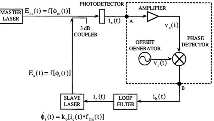
Fig. 4.1 - The optical injection phase-lock loop system, (a) homodyne, (b) heterodyne.
Fig. 4.2 - Detailed homodyne OIPLL bock diagram where the injection locking process is represented as a first order phase lock-loop of gain
Fig. 4.5 - Nyquist plot for second order OPLL (p = 0) and OIPLL (p
^
0) systems.Fig. 4.6 - FM noise spectral density of a single mode semiconductor laser, a: spontaneous emission noise; b: fluctuation of carrier density noise; c: self-heating noise; d: flicker noise (1/f noise); e: total FM noise.
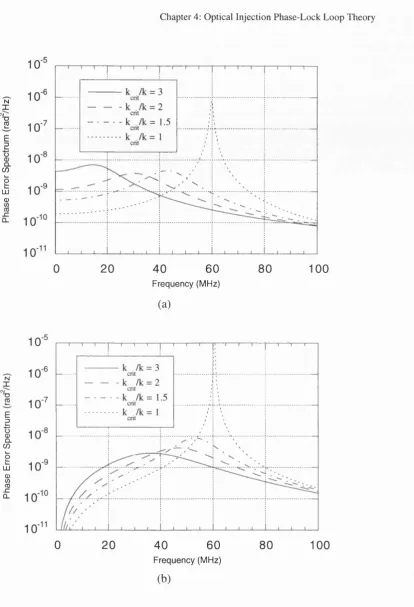
Fig. 4.7 - Phase error spectra for modified first order (a) and second order type n (b) OPLLs having the ratio between critical gain (Section 2.2) and the loop gain as a parameter, for loops with zero-delay damping ratio of 0.707.
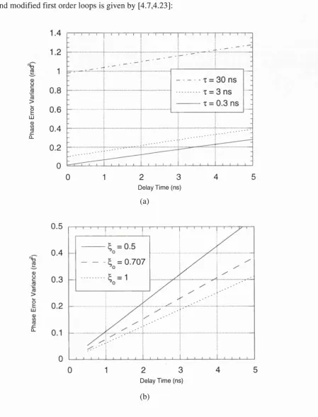
Fig. 4.8 - Phase error variance for a modified first order (a) and a second order type II (b) OPLL systems. The loop gain is set at 10 dB below the critical loop gain calculated for each point from the correspondent value of loop delay (Section 2.2).
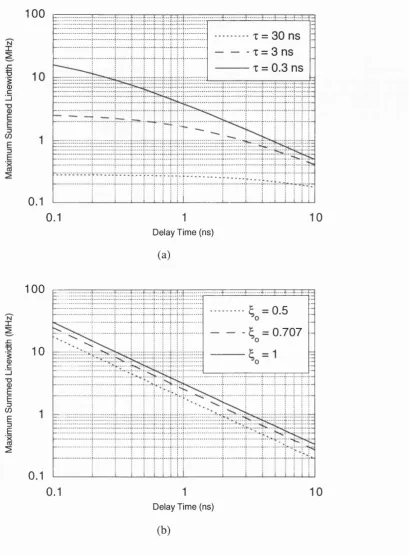
Fig. 4.9 - Maximum summed linewidth versus delay time for (a) a modified first order and (b) a second order type II OPLL system.
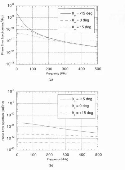
Fig. 4.10 - Phase error spectrum for OIL system with injection ratios o f -50 dB (a) and -30 dB (b), having the phase detuning between the lasers as a parameter.
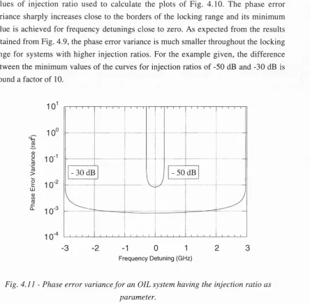
Fig. 4 .1 1 - Phase error variance for an OIL system having the injection ratio as parameter.
Fig. 4.12 - Phase error spectra for various optical locking techniques, with injected power ratio of -30 dB and total loop propagation delay of 3 ns.
Fig. 4.13 - Phase error variance for the OIPLL system versus the delay time, having the injection ratio as parameter. The gain of the OPLL part of the system was set to be 10 dB below the critical gain, as used to calculate Fig. 4.8.
Fig. 4.14 - Maximum OIPLL summed linewidth versus the delay time having the injection ratio (inj) as parameter. The integration bandwidth is 1 GHz, the loop gain was set to be the maximum stable gain for the equivalent OPLL and Tes = 10 years.
Fig. 4.15 - Block diagram of the OIPLL system showing the optical paths that contribute for Ojiff. The thickest line represents the electrical path.
Fig. 4.16 - Phase error spectrum of OIPLL system considering the effect of Ojiff. The parameters to calculate the curve for = 0° are the same as those used in Fig. 4.11.
Fig. 4.17 - Maximum master laser frequency detuning with path mismatch.
Chapter 5:
system; LSA: lightwave signal analyser.
Fig. 5.2 - The bulk optics OIPLL. ML: master laser; SL: slave laser; L: lens; ISO: isolator; H: half-wave plate; Q: quarter-wave plate; PBS: polarising beam splitter; M: mirror mounted on a translation stage; LSA: lightwave signal analyser; FPI: Fabry- Perot interferometer.
Fig. 5.3 - Schematic diagram o f the bulk-optics OIPLL w ith polarisation direction of the beams after each component. ML: master laser; SL: slave laser; P I: front polariser of commercial isolator; P2: rear polariser of commercial isolator; ISO: isolator crystal; H I and H2: half-wave plates; Q: quarter-wave plate; NBS: neutral beam splitter; PBS: polarising beam splitter; M: mirror.
Fig. 5.4 - Experimental arrangement for the OIPLL optical path matching. ML: master laser; SL: slave laser; L: lens; ISO: isolator; H: half-wave plate; PBS: polarising beam splitter; C: coupler; FC: fibre coupler; FPI: Fabry-Perot interferometer; PMPh: large area photodetector of the optical power meter.
Fig. 5.5 - Michelson interferometer response with frequency for different values of path mismatch between the two interferometer arms.
Fig. 5.6 - Schematic diagram of the front structure o f a buried-heterostructure DFB semiconductor laser (a). Detailed lateral view of the active region (b).
Fig. 5.7 - Optical power and voltage across the laser versus bias current for laser
1 (a) and laser 2 (b).
Fig. 5.8- O ptical spectrum for lasers 1 (a) and 2 (b). RBW : resolution bandwidth; VB: video bandwidth; ST: sweep time; SENS: sensitivity.
Fig. 5.9 - Schematic diagram of the linewidth measurement set-up using an optic fibre Mach-Zehnder interferometer. LUT: laser under test; L: lens; ISO: isolator; FC: fibre coupler; PC: polarisation controller; PH: photodetector; AMP: amplifier.
Fig. 5.10 - Comparison between the spectral spread of the laser optical spectrum and the result from the delayed self homodyne experiment.
Fig. 5.11 - Estimation of the laser 1 (a) and 2 (b) linewidths from the spectrum analyser measurements using the delayed self homodyne experiment of Fig. 5.9.
Fig. 5.12 - Set-up for the laser static tuning measurements. LUT: laser under test; FPI: Fabry-Perot interferometer; FC: optical fibre cable; ISO: isolator; L: lens.
Fig. 5.13 - Static tuning characteristic of laser 1 with current (a) and temperature (b).
Fig. 5.15 - The frequency discrim inator based on a hi-bi M ach-Zehnder interferometer. LUT: laser under test; L: lens; ISO: isolator; CR: fibre chuck rotators; HBF: hi-bi fibre; Q: quarter-wave plate; H: half-wave plate; PBS: polarising beam splitter; PH I and PH2: photodetectors.
Fig. 5.16 - Frequency discriminator response.
Fig. 5.17 - FM response for lasers 1 (a) and 2 (b) detected by a frequency discriminator based on a hi-bi Mach-Zehnder interferometer of resolution 11 GHz and measured by a network analyser. Static tuning sensitivity: laser 1, 0.8 GHz/mA, laser 2,
1.3 GHz/mA.
Fig. 5.18 - Balanced receiver for a single-facet homodyne OIPLL system. Q: quarter-wave plate; H: half-wave plate; PBS: polarising beam splitter; NBS: neutral beam splitter; PH I and PH2: photodetectors; L: lens; ISO: isolator.
Fig. 5.19 - W avefront mismatch between the master and slave laser signals. Fig. 5.20 - D egradation o f the dissipated pow er for the AC term o f the photocurrent as a function of wavefront misalignment.
Fig. 5.21 - Amplifier in summing configuration to combine the signals coming from the balanced photodetectors.
Fig. 5.22 - Schematic diagrams for voltage and current feedback amplifiers Fig. 5.23 - Conventional integrator configuration using voltage feedback amplifiers.
Fig. 5.24 - Integrator configuration using current feedback amplifier.
Fig. 5.25 - Transconductance stage to combine the laser bias with the loop signal.
Fig. 5.26 - Diagram of the loop circuit built. Fig. 5.27 - Loop circuit frequency response.
Fig. 5.28 - Real and ideal OPLL and OIPLL modelling considering the design parameters measured in previous sections. Injection ratio is assumed to be -31.4 dB.
Chapter 6:
Fig. 6.1 - The bulk optics OIPLL. ML: master laser; SL: slave laser; L: lens; ISO: isolator; H: half-wave plate; Q: quarter-wave plate; PBS: polarising beam splitter; M: m irror m ounted on a translation stage; PH I and PH2: photodetectors; LSA: lightwave signal analyser; FPI: Fabry-Perot interferometer.
resolution bandwidth; VB: video bandwidth; ST: sweep time; ATT: attenuation.
Fig. 6.4 - The experimental set-up for the monitoring path. ML: master laser; SL: slave laser; NBS: neutral beam splitter; H: half-wave plate; PBS: polarising beam splitter; ISO: isolator; C: coupler; FC: 3 dB fibre coupler; FPI: Fabry-Perot interferometer.
Fig. 6.5 - Beat signal spectrum measured by the lightwave signal analyser. Fig. 6.6 - OPLL spectrum obtained from the lightwave signal analyser. The loop parameters are such that ^ = 0.76.
Fig. 6.7 - The experimental configuration for the slave laser photocurrent measurement. ML: master laser; SL: slave laser; L: lens; ISO: isolator; H: half-wave plate; PBS: polarising beam splitter.
Fig. 6.8 - Photocurrent produced by the slave laser due to master laser power injection versus the rotation of the half-wave plate angle.
Fig. 6.9 - Experimental arrangement for the slave laser linewidth enhancement factor measurement. ML: master laser; SL: slave laser; L: lens; ISO: isolator; H: half wave plate; PBS: polarising beam splitter; NBS: neutral beam splitter; C: coupler; FC: fibre coupler; FPI: Fabry-Perot interferometer.
Fig. 6.10 - Voltage across slave laser versus locking range for the linewidth enhancement factor measurement.
Fig. 6.11 - Measured half-locking bandwidth versus the half-wave plate mount angle.
Fig. 6.12 - M easured and expected values for half-locking bandw idth and injection ratio for the OIL experiment.
Fig. 6.13 - M easured power spectral density o f the OIL system for different values of injection ratio and detuning. The lightwave signal analyser is set to lightwave- electrical mode: resolution bandwidth 300 kHz; video bandwidth 30 kHz; sweep time 166.7 s; attenuation 0 dB. (a) Injection ratio -47 dB, detuning -6.7 deg; (b) Injection ratio -36.4 dB, (b l) detuning -3 deg, (b2) detuning 7 deg; (c) Injection ratio -31.4 dB, (c l) detuning -4 deg, (c2) detuning 7 deg.
Fig. 6.14 - Power spectral density for the OIPLL system for injection ratios (a) -47 dB, (b) -36.4 dB and (c) -31.4 dB. RBW: resolution bandw idth; VB: video bandwidth; ST: sweep time; ATT: attenuation.
Fig. 6.16 - Phase error variance for OIL and OIPLL systems as a function of the detuning betw een m aster and slave laser frequencies. Injection ratio -47 dB. M easurement bandwidth 500 MHz.
Fig. 6.17 - Phase error variance for OIL and OIPLL systems as a function of the detuning betw een m aster and slave laser frequencies. Injection ratio -36.4 dB. M easurement bandwidth 500 MHz.
Fig. 6.18 - Phase error variance for OIL and OIPLL systems as a function of the detuning betw een m aster and slave laser frequencies. Injection ratio -31.4 dB. Measurement bandwidth 500 MHz.
Chapter 7:
Fig. 7.1 - Block diagram of a heterodyne OIPLL using side frequency locking of slave laser.
Fig. 7.2 - Diagram of an OIPLL in a planar OEIC structure. ML: master laser; SL: slave laser; WG: wave guide; MOD: modulator; C: coupler; PH I and PH2: photodetectors; AMP: amplifier; LF: loop filter.
Appendix A:
Fig. A. 1 - Schematic diagram of a fibre-based coherent detection system.
Appendix B:
Fig. B .l - Longitudinal section of the laser active area.
Appendix D:
Fig. D .l - Variable ratio beam splitter for linearly-polarised light inputs. Case A: full reflection, (p = 0°. Case B: full transmission, (p = 45°.
Fig. D.2 - Diagram of a commercial isolator based on the Faraday rotation effect and the schematic representation of it.
Appendix F:
components.
Fig. F.3 - Representation of the principal and delayed axes of the quarter-wave plate and the relative position of the fast axis at the hi-bi fibre output.
Fig. F.4 - Orientation of the quarter wave-plate axes in relation to the half-wave plate axes for the fast axis of the hi-bi fibre.
Fig. F.5 - Polarising beam splitter orientation axes in relation to the half-wave plate axes for the fast hi-bi fibre axis.
Fig. F.6 - Representation of the principal and delayed axes of the quarter-wave plate and the relative position of the slow axis at the hi-bi fibre output.
Fig. F.7 - Orientation of the quarter wave-plate axes in relation to the half-wave plate axes for the slow axis of the hi-bi fibre.
Chapter 1
Introduction
This Chapter introduces the optical injection phase-lock loop (OIPLL) and its applications. Laser locking techniques and their limitations are reviewed. The OIPLL system is then presented. A summary of the possible applications o f the OIPLL configuration is given and the structure of the thesis is presented.
1.1 - Locking Techniques
single laser source with a finite frequency error and the improvement of the technique w ould require more complex feedback loops, with the addition of extra integration, making the system susceptible to instabilities.
The synchronisation of two independent laser sources required the development of locking techniques. The basic principle in these systems is that the frequency of a laser source, known as slave source, follows the frequency variation o f another laser source, known as master source. Different laser frequency synchronisation methods and configurations have been widely investigated, with the principles involved very similar to those used in electronic and/or microwave systems [1.6-1.10,1.29]. In this Section, the optical phase-lock loop [1.11-1.28] and optical injection locking [1.30-1.54] techniques are discussed, showing the different system configurations, previous works and principal limitations. In the next section, the optical injection phase-lock loop [1.61-1.62] is introduced as a solution for the optical phase-lock loop and optical injection locking main operational problems.
1.1.1 - The Optical Phase-Lock Loop
The optical phase-lock loop (OFLL) is a feedback system that controls the optical phase of an optical source to follow the optical phase excursions of an incoming optical signal. This is done by comparing the phase of the input signal to that of the local optical source, generating a phase error signal responsible for the local source frequency control. As the local signal source frequency is controlled to follow the changes in the input signal phase, the local source will be referred to as the slave source whilst the input signal source will be referred to as the master source.
Fig. 1.1 shows the general schematic diagram of an OPLL. The general schematic diagram corresponds to that of the heterodyne OPLL. In heterodyne systems, master and slave sources operate at different frequencies. The signals from both sources are mixed on the active area of a photodetector, producing at its output a beat signal at a frequency corresponding to the frequency offset between the two sources. A phase detector compares the phase of the beat signal to that of an offset generator operating at a frequency close to that of the beat signal. A phase error signal is then produced at the output of the phase detector. The loop filter processes this signal and tunes the slave laser in such a way as to minimise the phase error. The loop acquires lock when the frequency offset between the two optical sources is kept constant and equal to that of the offset generator.
Chapter 1 : Introduction
homodyne systems, master and slave sources oscillate at the same frequency and the photodetector is responsible for the phase detection. The signals from both sources are m ixed on the active area of the photodetector, which generates a photocurrent proportional to the phase difference between the two signals. This phase error signal is then processed by the loop filter, tuning the frequency of the slave laser to minimise the phase error of the loop. The loop acquires lock when the frequency offset between the lasers is zero.
PHOTODETECTOR
AMPLIFIER
PHASE DETECTOR OFFSET
GENERATOR MASTER
SOURCE
LOOP FILTER SLAVE
SOURCE
Fig. 1.1 - General block diagram o f an OPLL system.
The utilisation of OPLL systems has been limited in the past by a series of technological problems. One of them, and perhaps the m ost im portant, was the availability of suitable optical sources. The optical sources normally used were lasers and, these present wideband phase noise along with poor frequency tuning response and frequency instability. The advent of semiconductor lasers provided compact and readily tunable sources making the OPLL a promising technique for laser synchronisation.
A fter that, many other works appeared using different type o f lasers and different
techniques of frequency tuning were tried. A homodyne system was realised using CO2
lasers [1.12] operating at 10.6 pm and tuned by a combination of piezoelectrically positioned mirror and internal electro-optic frequency modulator. Heterodyne systems were also achieved with HeNe lasers, generating 2 MHz [1.13] and 5 MHz signals [1.14]. M ore recently, solid state lasers have been used in homodyne [1.15,1.16] and heterodyne OPLLs generating 4 GHz [1.17] and 12 GHz [1.18] modulated signals. In all cases, very narrow linewidth, and, therefore, low phase noise lasers, were used (linewidth less than 200 kHz).
The use of semiconductor lasers would ensure faster and simpler tuning as any frequency correction could be achieved directly through the laser bias current. H ow ever, the amount of phase noise that such sources presented prevented their utilisation in OPLL systems. Line narrowing techniques had to be applied to correct the sem iconductor laser phase noise problem . One o f the first experim ents using semiconductor lasers was an heterodyne OPLL where weakly coupled external cavities were used to narrow the system semiconductor laser linewidths [1.19]. In order to minimise the complexity of the OPLL system, the utilisation of two different types of laser in homodyne OPLL configurations has also been proposed, where a LiNbOg modulator tuned external cavity semiconductor laser was locked to a HeNe laser input signal [1.20]. External cavity sem iconductor lasers were im proved and used in heterodyne OPLLs, generating signals at 250 MHz [1.21], and in homodyne OPLLs [1.22]. Another way of narrowing the semiconductor laser linewidth was to employ optical feedback from external high finesse resonators. This technique was used in heterodyne OPLLs, achieving 25 MHz [1.23] and 40 MHz [1.24] generated signals, and in homodyne OPLLs [1.25].
Chapter 1 : Introduction
requirements for practical values of loop propagation delay. The loop delay limits the loop gain and bandwidth and, therefore, the phase noise suppression of the system. Unless complex loop electronics [1.26] or passive loop filters [1.27] are built, measures that can ensure short loop delay, the poor phase noise suppression requires the linewidth of the laser to be narrow (less than few MHz) to provide acceptable loop performance.
In Chapters 2 and 4, the limitations imposed by the loop propagation delay on the loop gain and bandwidth and laser linewidth will be discussed and the difficulties of implementing stable OPLLs with non line-narrowed semiconductor lasers will become apparent.
1.1.2 - Optical Injection Locking
Optical injection locking (OIL) is another frequency synchronisation technique that has been applied to optical sources. The principle is simple as locking is obtained by injecting part of the output light generated by a master source into the laser cavity of a slave source. The injected signal stimulates emission inside the slave source cavity in such a way that the slave source frequency is pulled from its free running value to that of the m aster source. Fig. 1.2 shows the schematic diagram of a general injection locking experiment. The OIL is basically an homodyne technique. However, by placing a phase modulator between the points A and B inside the injection path and locking the slave source to one of the side frequencies of the optical m aster modulated signal, a heterodyne configuration can be obtained, as a beat signal at a frequency corresponding to the m aster signal m odulating frequency is produced at the output o f the photodetector. Depending on the type of laser, similar heterodyne behaviour can be obtained by modulating directly the master source and locking the slave source to one of the modulation side bands.
PHOTODETECTOR MASTER
SOURCE
R-o
SLAVESOURCE ! MODULATOR:
The idea of the synchronisation of two sources by injection locking dates from the first theoretical and experimental reports about the injection locking of electronic oscillator [1.29] and the application of the injection locking principle to laser sources was straightforward. The injection locking of light sources has been demonstrated with many types of laser. Some examples are the injection locking experiments using CO2
[1.30], X eF [1.31] and flash lamp pum ped dye [1.32] lasers. One o f the first semiconductor laser injection locking experiments used a system comprising AlGaAs double heterostructure Fabry-Perot lasers [1.33]. The dependence o f the locking bandwidth on the injected power was observed in a system using two AlGaAs double heterostructure Fabry-Perot semiconductor lasers [1.34], where a theoretical model for the injection locking of semiconductor lasers was also presented. The first experiment reporting the heterodyne injection locking of semiconductor lasers used GaAlAs lasers and produced locked signals up to 9.5 GHz, with locking bandwidth of 400 M Hz and low level injection [1.35]. The asymmetry of the OIL locking bandwidth was reported [1.36] and a sequence of the first detailed theoretical studies of the OIL process of semiconductor lasers followed [1.37-1.40]. Also an investigation of instabilities inside the locking range for higher levels of injection was reported [1.41] and the injection process using DFB lasers started to be developed [1.42]. Full theoretical and experimental works on Fabry-Perot [1.43-1.47] and DFB [1.48-1.50] lasers were later presented. The utilisation of the OIL process also offered a way to measure the effective linew idth enhancem ent factor o f the injected sem iconductor laser [1.51-1.54]. Compared to the OPLL process, the OIL does not suffer the delay time limitations as no feedback loop is present and the phase noise suppression achieved with the OIL process depends only on the amount o f injected power into the slave laser cavity [1.48]. Therefore, there is no necessity for extremely narrow linewidth lasers to obtain low levels of phase noise in the OIL system. However, high level injection compromises the stability of the locking range in such a way that only a narrow part of the range is useful [1.44,1.47,1.49]. In Chapter 3 and 4, the theoretical analysis of the OIL process is presented, and the locking range limitations and phase noise suppression characteristics are given.
1.2 - The Optical Injection Phase-Lock Loop
Chapter 1 : Introduction
m aster laser light into the slave laser cavity is also present, introducing an extra dam ping term to the system and relaxing the restrictions that apply to OPLL configurations. The phase of the input signal is compared with the phase o f the slave laser. W hile the injection locking part of the OIPLL is mostly responsible for the phase noise suppression o f the system, the feedback loop tracks low frequency phase excursions of the master laser by controlling the phase emission of the slave laser in the same way as in the OPLL case.
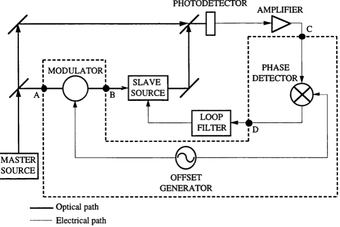
Fig. 1.3 shows the general block diagram of an heterodyne OIPLL system. By disregarding the components inside the dashed box and connecting points A and B and C and D, an homodyne OIPLL system is formed. Part of the light from the master laser is injected into the slave laser cavity for the OIL process. The other part is combined with the output light of the slave laser on the active area of the photodetector for the OPLL part o f the system. The phase error signal generated at the output o f the photodetector is processed by the loop filter and tunes the slave laser in order to minimise the phase error. Locking is acquired when the two lasers oscillate at same frequency.
PHOTODETECTOR
Optical path Electrical path
AMPLIFIER
PHASE DETECTOR u
m o d u l a t o r!
OFFSET GENERATOR SLAVE
SOURCE
LOOP FILTER MASTER
SOURCE
Fig. 1.3 - General block diagram of an OIPLL.
of the system. The other part of the master laser light is combined with the output light from the slave laser on the active area of the photodetector for the OPLL part of the system, generating a beat signal at a frequency corresponding to the frequency offset between the two lasers. The phase of the beat signal is compared with the phase of the signal generator by a phase detector. The phase error signal generated at the output of the phase detector is processed by the loop filter and tunes the slave laser in order to minimise the phase error. Locking is acquired when the frequency offset between the two lasers is equal to the signal generator frequency.
The idea of synchronising two sources using a com bined phase-lock and injection locking system has already been used in the control of electronic oscillators. First, homodyne configurations were proposed, where the stabilisation of high power level oscillations with low power level signals of high stability and low noise was achieved [1.55,1.56]. The generation of 11 GHz carriers for microwave systems using phase lock and injection locking control of a voltage controlled oscillator [1.57] was reported. It was not long until hybrid injection phase-lock loops started to appear. In these systems, the injection of electronic signals was substituted by the injection of laser light into the electronic oscillator. Many different configurations were proposed [1.58-1.60] and they found their main application in microwave signal generation. Recently, theoretical analyses of the utilisation of injection locking and phase lock control o f laser sources, in particular, using sem iconductor lasers, were reported [1.61,1.62].
Chapter 1 : Introduction
lasers is presented, where the main advantages and limitations of such a system in relation to the equivalent OPLL and OIL systems are presented.
1.3 - OIPLL Applications
The OIPLL technology can find many applications in optical communication systems. The fact that semiconductor lasers without narrowing techniques can offer compact and low cost systems makes the implementation of OIPLL configurations even more attractive.
The simplest and most common optical fibre data transmission scheme uses intensity modulation of the optical source. At the receiver, the information transmitted through an optical fibre is recovered by means of the direct detection of the fluctuations of the beam intensity by a photodetector. This method offers simplicity and relatively low cost, but suffers from limited sensitivity and does not uses the wide bandwidth capabilities of the optical fibres.
Despite the theoretical possibilities of coherent detection systems, it was only by the beginning o f the nineteen-eighties that sem iconductor laser structures were sufficiently developed to produce stable frequency and spectrally pure devices in such a way that coherent detection configurations [1.19] could be practical. Coherent optical systems are very similar to radio systems in the sense that, like the radio carrier, the optical carrier can also be modulated using different m odulation form ats and the detection process down-converts the information from the optical carrier to a much lower frequency where it can be treated electronically. The frequency conversion is made by mixing the incoming modulated optical signal with a local oscillator laser signal. The im provem ent of the w avelength/frequency selectivity and receiver sensitivity are the main advantages of coherent systems com pared to the direct detection systems. Therefore, not only would coherent systems offer optical fibre links with longer distance between repeaters but also they would allow a further step towards the utilisation of the bandwidth potential of the optical fibres. The w avelength selectivity provided by the coherent receiver could easily be used to access the wide optical bandw idth o f the optical fibre as frequency and w avelength division multiplexing are possible with very narrow channel spacing. This characteristic is nowadays becoming more important than the improved receiver sensitivity in long distance com m unication links due to the developm ent o f optical fibre am plifier technology.
are around 1300 and 1550 nm. The regions of these windows used in coherent communication are from 1270 to 1350 nm and from 1480 to 1600 nm, respectively. For a system whose channel spacing is 5 GHz, it would theoretically be possible to obtain at least 2800 channels in the 1300 nm window and 3000 channels in the 1550 nm window. However, the possibility of making such systems will depend on the ability to develop coherent systems that can be tuned over a significant part of the fibre bandwidth and still offer high degree of stability and temporal coherency, and a suitable coding method for inserting data on the optical carrier. Analog formats modulate the coherent optical carrier in amplitude, frequency and phase before demodulation using coherent optical receivers. In the case of digital transmission, amplitude, frequency and phase shift keyed modulation techniques can be applied.
The OIPLL configuration is basically a coherent technique and can offer wide tunability while tracking temporal fluctuations in phase. With the tuning capability of OIPLL systems, not only could OIPLL be used in coherent detection but also in the generation and detection of closely spaced carriers for different channels in multiplex systems.
1.4 - Structure of the Thesis
The first aim of this thesis is to compare the locking techniques described in Sections 1.1 and 1.3, providing an understanding of the mechanisms involved in each one of them, with special attention to the OIPLL characteristics. The OIPLL limitations and modelling are studied and set the guidelines for an experimental design. The second objective is to present the design, construction and evaluation of the first OIPLL.
Chapter 2 presents the theoretical analysis of the OPLL system. The general block diagram and general set of equations in tim e and frequency dom ain for hom odyne and heterodyne system s are presented, considering non-zero loop propagation delay time. Discussions of the loop filter design and loop stability are introduced. Finally, the main sources of noise are identified.
In Chapter 3, the basic principles of the optical injection locking system are introduced. The block diagram and equations in time and frequency domain for an OIL system are presented. The effect of increasing the level of injection power into the slave laser cavity and the stability of the locking process are analysed. Considering the OIL equations, a simple model for the injection locking system based on phase-lock loop theory is presented, leading to the system noise characterisation.
Chapter 1 : Introduction
diagrams for homodyne and heterodyne systems and the homodyne OIPLL equations in time and frequency domain are presented, considering non-zero loop propagation delay. System stability for different loop filter configurations is analysed with and without injection (OPLL case). The main noise sources are identified and a full analysis and comparison of the performance of the different locking techniques is conducted, based on the phase error spectrum and phase error variances of the different systems. Finally, the OIPLL analysis is completed by considering the phase shifts in the phase detection process due to optical path mismatch.
Chapter 5 concentrates on the optical and electrical design of an experimental OIPLL. The design of an experimental arrangem ent that could accom modate OIL, OPLL and OIPLL techniques, offering a reasonable way of controlling the optical path m ismatch is presented. The main characteristics o f the optical sources used in the OIPLL experiment are described and measured, including the tuning characteristics of the laser sources. The design of the optoelectronic balanced receiver is presented along with a method to obtain effective optical wave overlap. Finally, the design of the loop electronics is presented, starting by giving an overview of each part of the loop circuit, followed by measurements of the circuit response.
Chapter 6 presents experimental results for the first OIPLL, along with results obtained for the equivalent OPLL and OIL systems used alone, applying the techniques, m odelling and design detailed in previous Chapters. Parameters of the experimental systems are measured and the phase noise suppression performance of the three locking techniques are presented and compared with each other and with the theoretical predictions.
Chapter 7 presents a sununary of the main conclusions of this project and gives suggestions for future work.
References
[1.1] Y. A. BYKOVSKII et al.: "Use of a Fabry-Perot resonator for the stabilization of the frequency of an injection laser",
Sov. Phys.-Semiconductors,
vol. 4, pp. 580-583, 1970.[1.2] C. J. NIELSEN and J. H. OSMUNDSEN: "New approach towards frequency stabilization of narrowed semiconductor lasers".
Electron. Lett.,
vol. 19, pp. 644-646, 1983.[1.4] S. YAMAGUCHI and M. SUZUKI: "Frequency stabilization of a diode laser by use of the optogalvanic effect",
Apply. Phy s. Lett,
vol. 1 1 ,pp. 597-598,1982.
[1.5] S. YAM AGUCHI and M. SUZUKI: "Frequency locking o f an InG aA sP
semiconductor laser to the first overtone vibration-rotation lines of hydrogen fluoride", App/y.
Phys. Lett.,
vol. 11, pp. 1034-1036, 1982.[1.6] H. BELLESCIZE: "La reception synchrone".
Onde Electron.,
vol. 11, pp. 230- 240, 1932.[1.7] K. R. W ENDT AND G. L. FREDEND ALL : "Automatic frequency and phase
control of synchronization in television receivers",
Proc. IRE,
vol. 31, pp. 7- 15, 1943.[1.8] G. R. VAUGHAN, E. F. OSBORNE and G. S. ENTW ISTOLE: "Locked
oscillator phase modulator", NASA Report N65-29140, Appendix D, 1964.
[1.9] M. PETER and M. W. P. STRANDBERG: "Phase stabilization of microwave
oscillators",
Proc. IRE,
no. 43, pp. 869-873, 1955.[1.10] J. H. SCHADER: "A phase-lock receiver for the arraying o f independently directed antennas",
IEEE Trans.,
vol. AP-12, no. 2, pp. 155-161, 1964.[1.11] L. H. ENLOE and J. L. RODDA: "Laser phase-locked loop",
Proc. IEEE,
vol. 53, no. 2, pp. 165-166, 1965.[1.12] W. R. LEEB, H. K. PHILIPP, A. L. SCHOLTS and E. BONEK: "Frequency stabilisation and phase locking of CO2 lasers",
Appl. Phys. Lett,
vol. 41, no. 7, pp. 592-594, 1982.[1.13] J. SOOHOO and C. L. HAYES: "Phase locking of a multimode to a single mode He-Ne laser".
Optics Lett,
vol. 4, no. 7, pp. 202-204, 1979.[1.14] J. L. HALL, M. L. SHENG and G. KRAMER: "Principles o f phase-locking: application to internal mirror HeNe lasers phase-locked via fast control of the discharge current",
IEEE J. Quantum Electron.,
vol. QE-23, no. 4, pp. 427- 437,1987.[1.15] L. G. KAZOVSKY and D. A. ATLAS: "A 1320 nm experim ental optical phase-locked loop",
IEEE Photon. Technol. Lett,
vol. 1, no. 11, pp. 395-397,1989.
[1.16] L. G. KAZOVSKY and D. A. ATLAS: "A 1320-nm experim ental optical
phase-locked loop: performance investigation and PSK homodyne experiments at 140 Mb/s and 2 Gb/s",
Joum. Lightwave Technol.,
vol. 8, no. 9, pp. 1414-Chapter 1 : Introduction
[1.17] D. A. ATLAS and L. G. KAZO V SK Y : "2 G bit/s PSK h eterodyne
communication system using optical phase-locked loop",
Electron. Lett.,
vol. 26 no. 14, pp. 1030-1032, 1990.[1.18] M. J. W ALE and M. G. HOLLYDAY: "Microwave signal generation using optical phase-locked loops", European M icrowave Conference, workshop A proceedings, pp. 77-82, 1991.
[1.19] R. C. STEELE: "Optical phase-locked loop using semiconductor laser diodes".
Electron. Lett.,
vol. 19, no. 2, pp. 69-70, 1983.[1.20] D. J. M AYLON, D. W. SMITH and R. W YATT: "Sem iconductor laser
homodyne optical phase locked loop".
Electron. Lett.,
vol. 22, no. 8, pp. 421- 422, 1986.[1.21] J. HARRISON and A. M OORADIAN: "Linewidth and offset frequency
locking of external cavity GaAlAs lasers",
IEEE J. Quantum Electron.,
vol. QE-25, no. 6, pp. 1152-1155, 1989.[1.22] J. M. KAHN: "1 Gbit/s PSK homodyne transmission system using phase- locked semiconductor lasers",
IEEE Photon. Electron. Lett.,
vol. 1, no. 10, pp. 340-342, 1989.[1.23] C. H. SHIN and M. OHTSU: "Heterodyne optical phase-locked loop by confocal Fabry-Perot cavity coupled AlGaAs lasers",
IEEE Photon. Technol.
Lett.,
vol. 2, no. 4, pp. 297-300, 1990.[1.24] H. R. TELLE and H. LI: "Phase-locking of laser diodes".
Electron. Lett.,
vol. 26, no. 13, pp. 858-859, 1990.[1.25] C. H. SHIN and M. OHTSU: "Homodyne optical phase locking of resonant cavity coupled semiconductor lasers",
IEEE J. Quantum Electron.,
vol. 29, no. 2, pp. 374-385, 1993.[1.26] R. T. RAMOS and A. J. SEEDS: "Fast heterodyne optical phase-lock loop using double quantum well laser diodes".
Electron. Lett.,
vol. 28, no. 1, pp. 82- 83, 1992.[1.27] U. GLIESE, N. T. NIELSEN, M. BRUUN, E. L. CHRISTENSEN, K. E.
STUBKJAER, S. LINDGREN and B. BROBERG: “A wideband heterodyne optical phase-locked loop for generation of 3-18 GHz microwave carriers” ,
IEEE Photon. Technol. Lett.,
vol. 4, no. 8, pp. 936-8, 1992.[1.28] G. SANTARELLI, A. CLAIRON, S. N. LEA and G. M. TINO: "Heterodyne optical phase-locking of extended-cavity semiconductor laser at 9 GHz",
Optics Comm.,
vol. 104, no. 4, 5, 6, pp. 339-344, 1994.[1.30] J. L. LACHAM BRE, P. LA VIGNE, G. OTIS and M. NOËL: "Injection locking and mode selection in TEA-CO2 laser oscillators",
IEEE J. Quantum
Electron.,
vol. QE-12, no. 12, pp. 756-764, 1976.[1.31] J. GOLDHAR, J. DICKIE, L. P. BRADLEY and L. D. PLEASANCE:
"Injection locking of a xenon fluoride laser",
Appl Phys. Lett.,
vol. 31, no. 10, pp. 677-679, 1977.[1.32] S. BLIT, U. GANIEL and D. TREVES: "A tunable, single mode, injection- locked flashlamp pumped dye laser",
Appl Phys.,
vol. 12, no. 1, pp. 69-74,1977.
[1.33] S. KOBAYASHI and T. KIMURA: "Coherence of injection phase-locked
AlGaAs semiconductor laser".
Electron. Lett.,
vol. 16, no. 7, pp. 668-670, 1980.[1.34] S. KOBAYASHI and T. KIMURA: "Injection locking characteristics of an AlGaAs semiconductor laser",
IEEE J. Quantum Electron.,
vol. QE-16, no. 9, pp. 915-917, 1980.[1.35] L. GOLDBERG, H. F. TAYLOR and J. F. WELLER: "FM sideband injection locking of diode lasers".
Electron. Lett.,
vol. 18, no. 23, pp. 1019-1020, 1982. [1.36] K. KOBAYASHI, H. NISHIMOTO and R. LANG: "Experimental observationo f asym m etric detuning characteristics in sem iconductor laser injection locking"
Electron. Lett.,
vol. 18, no. 2, pp. 54-56, 1982.[1.37] K. OTSUKA and S. TARUCHA: "Theoretical studies on injection locking and injection-induced modulation of laser diodes",
IEEE J. Quantum Electron.,
vol. QE-17, no. 8, pp. 1515-1521, 1981.
[1.38] R. LANG: "Injection locking properties of a semiconductor laser",
IEEE J.
Quantum Electron.,
vol. QE-18, no. 6, pp. 976-983, 1982.[1.39] C. H. HENRY : "Theory of the phase noise and power spectrum of a single mode injection laser",
IEEE J. Quantum Electron.,
vol. QE-19, no. 9, pp. 1391-1397, 1983.[1.40] P. G ALLION and G. DEBARGE: "Influence of amplitude-phase coupling on the injection bandwidth of a semiconductor laser".
Electron. Lett.,
vol. 21, no. 7, pp. 264-266, 1985.[1.41] G. G R 06K O PF and L. KÜLLER: "Experimental study of stability properties o f injection-locked InG aA sP/InP laser diodes".
Optical and Quantum
Electron.,
vol. 17, pp. 269-275, 1985.Chapter 1 : Introduction
semiconductor lasers",
Joum. Lightwave Technol.,
vol. LT-3, no. 1, pp. 63-67, 1985.[1.43] F. M OGENSEN, H. OLESEN and G. JACOBSEN: "Locking conditions and
stability properties for a semiconductor laser with external light injection",
IEEE J. Quantum Electron.,
vol. QE-21, no. 7, pp. 784-793, 1985.[1.44] C. H. HENRY, N. A. OLSON and N. K. DUTTA: "Locking range and
stability of injection locked 1.54 |xm InGaAsP semiconductor lasers",
IEEE J.
Quantum Electron.,
vol. QE-21, no. 8, pp. 1152-1156, 1985.[1.45] P. SPANO, S. PIAZZOLLA and M. TAMBURRINI: “Frequency and intensity
noise in injection-locked semiconductor lasers: theory and experiments”,
IEEE
J. Quantum Electron.,
vol. QE-22, no. 3, pp. 427-435, 1986.[1.46] I. PETITBON, P. GALLION, G. DEBARGE and C. CHABRAN: "Locking
bandw idth and relaxation oscillation o f an injection-locked semiconductor laser",
IEEE J. Quantum Electron.,
vol. 24, no. 2, pp. 148-154, 1988.[1.47] O. LIDOYNE, P. GALLION, C. CHABRAN and G. DEBARGE: “Locking
range, phase noise and power spectrum of an injection-locked semiconductor laser” ,
lEE Proc.,
vol. 137, pt. J, no. 3, pp. 147-154, 1990.[1.48] K. KIKUCHI and C. E. ZAH: "Spectral phase noise and phase modulation characteristics of AM sideband injection-locked sem iconductor lasers".
Electron. Lett.,
vol. 23, no. 9, pp. 437-439, 1987.[1.49] R. HUI, A. MECOZZI, A. D ’OTTAVI and P. SPANNO: "Injection locking in distributed feedback semiconductor lasers:",
IEEE J. Quantum Electron.,
vol. 27, no. 6, pp. 1688-1695, 1991.[1.50] T. OGAWA, Y. IDA and K. HAYASHI: "Experimental determination of gain compression factors of a DFB laser in presence of TM light injection"
IEEE
Photon. Electron. Lett.,
vol. 4, no. 4, pp. 345-348, 1992.[1.51] R. HUI, A. D ’OTTAVI, A. MECOZZI and P. SPANNO: "Novel measurement
technique of a factor in DFB semiconductor lasers by injection locking".
Electron. Lett.,
vol. 26, no. 14, pp. 997-998, 1990.[1.52] H. N AKA JIM A and J. C. BOULEY: "O bservation o f pow er dependent linew idth enhancem ent factor in 1.55 p m strained quantum well lasers".