http://dx.doi.org/10.4236/ars.2015.42013
A Synoptic Review on Deriving Bathymetry
Information Using Remote Sensing
Technologies: Models, Methods and
Comparisons
Shridhar D. Jawak1, Somashekhar S. Vadlamani2, Alvarinho J. Luis1
1Polar Remote Sensing Division, Earth System Science Organization (ESSO), National Centre for Antarctic & Ocean Research (NCAOR), Ministry of Earth Sciences, Vasco-Da-Gama, India
2Department of Civil Engineering, Symbiosis Institute of Technology, Symbiosis International University, Pune, India
Email: [email protected], [email protected], [email protected]
Received 22 May 2015; accepted 26 June 2015; published 29 June 2015
Copyright © 2015 by authors and Scientific Research Publishing Inc.
This work is licensed under the Creative Commons Attribution International License (CC BY).
http://creativecommons.org/licenses/by/4.0/
Abstract
bathymetry derivation methods/algorithms and their implications in practical applications.
Keywords
Optical Remote Sensing, Bathymetry, SAR, LIDAR, Stumpf Model, Jupp’s Model, Lyzenga Model
1. Introduction
Hydrography measures the physical features of water bodies with their prediction of change over time, which includes not only bathymetry, but also the shape and features of the shoreline, the characteristics of tides, cur-rents, waves, and the physical and chemical properties of the water for the purpose of safe navigation [1]. Ba-thymetry is a method of quantifying depths to study the topography of water bodies, including oceans, seas, riv-ers, streams, and lakes. The measurement of bathymetry using satellite imagery is one of the fundamental re-searches in the field of remote sensing (RS) of the marine environment, which has numerous practical applica-tions to the coastal environment and its monitoring. Accurate determination of water depth is essential for vari-ous purposes such as monitoring underwater topography, movement of deposited sediments, and producing ma-ritime charts for navigation. Such information is also vital for port facility management, dredging operations,
and to predict channel infill and sediment budget. Bathymetric information plays an essential role in all branches of oceanography, paleoclimate studies, and marine geology. Bathymetric mapping is the process of making ba-thymetric maps based upon the depth data. Baba-thymetric maps represent the water body depth as a function of geographical coordinates, similar to topographic maps representing the altitude of Earth’s surface at different geographic coordinates. The most popular type of bathymetric maps is represented by lines of equal depths called isobaths [2]. Nowadays, bathymetry is mapped using echo sounders and the depth datasets are processed to compile nautical charts, shaded relief maps, and digital terrain/bathymetric models. Bathymetric data are gener-ally used to generate navigational charts, 3D models, and seafloor profiles. Traditiongener-ally, ocean floor data are collected by measuring the time taken by the laser light, or an acoustic sonar pulse, to travel through the water column to the ocean floor and back, based on the speed of sound in water, sensor characteristics, time, and other variables. Spatial resolution, coverage, temporal resolution and data type vary among the different bathymetry acquisition systems [3]. Traditional bathymetric acquisition methods are capable of generating accurate point measurements or depth profiles along transects, but are constrained by their inefficiency, logistical expenses and inaccessibility in remote areas . Environmental conditions and technical restraints avoid their explicabilities to near-shore waters [4] as shallow coastal waters are perilous for navigation, especially during low tides. An al-ternative is to combine the shipboard and the satellite data to improve bathymetric prediction [5]. By comparison, RS method is faster and applicable to various environments, including shallow coastal waters, and clear rivers
Table 1.Types of non-imaging and imaging systems with their strengths and limitations (source: modified from Gao [7]).
Method Sensor Type Accuracy Controlling Factors Advantages Drawbacks Scope of Application
Imaging Microwave or SAR
sensor Active Relatively low
Image resolution, slicks, waves, fronts, weather condition
- Applicable over large areas - Unaffected by cloud cover
- Relative low accuracy Bathymetry derivation from open oceanic waters Non-
imaging Radar Altimetry Active Very low accuracy
Elastic thickness of the lithosphere and/or crustal thickness, sediments
Global coverage, needs only simple altimetry with no iono/tropo-sphere measurement
Possible over a limited wavelength band Coarse bathymetry derivation for oceans Non-
imaging LIDAR Active ≈15 cm
Water clarity or turbidity, bed material, surface state
Wide depth range; concurrent measurement not essential - Expensive - Limited swath width Varied aquatic environments of narrow range
Imaging Optical (analytical) Passive Relatively high
Water quality (clarity or turbidity), cloud cover, atmospheric conditions
- Based on physical process
- Relatively higher accuracy
- Complex execution as input parameters are required - Real-time in-situ data essential
Turbid and shallow inland waters, estuaries, river channels
Imaging Optical (empirical) Passive Varying accuracy
Atmospheric calibration, water turbidity, bottom reflectance
- Simple to execute - Accurate at definite depth
- Limited depth - Accuracy lower at a larger depth - Real-time ground truth essential
Near shore and coastal waters, open waters
Imaging Video Passive Relatively high Image resolution - Capable to produce minor bathymetric change Restricted area Bathymetry along profiles Intertidal zone and estuaries
of the returned radiation pulses from the object at the sensed spots, which is eventually used to produce bathy-metric information. However, this method is limited by the coarse bathybathy-metric sampling interval and high cost. The basic assumption for deriving ocean bed topography from satellite altimeter measurements (non-imaging method) is summarized elsewhere [9]. The conceptual approach employs the sparse depth sounding measure-ments to restrict the long-wavelength depth while the shorter-wavelength topography is envisaged from the down-ward-continued satellite gravity measurements [10]. On the other hand, imaging methods approximate the water depth based on the pixel values or digital numbers (DN) of an image. Imaging methods make use of the visible and/or near infrared (NIR) light and microwave radiation. Radio detection and ranging (radars) are imaging sensors whilst radar altimeters and scatterometers are non-imaging sensors used for bathymetry derivation. Ra-dar satellites use short pulses of electromagnetic radiation (EMR) in the microwave range (10 s or 100 s of GHz), therefore they do not depend on daylight and are unaffected by wind, fog, dust, clouds, and bad weather condi-tions. These satellites measure the radar pulses reflected from the ground surface, evaluate the signal strength or intensity to recover information on the structure of the earth’s surface, and identify the elapsed time between pulse emission and return. In case of microwave imagery, radar observes the backscattered variations from the sea surface, e.g. roughness caused by modulations in the wave spectrum with respect to the surface current [11]. Such variations in the current velocity at the ocean surface can be recognized because of interactions between tidal flow and bed topography. Although imaging method using microwave data is not subject to cloud cover, it is rather complicated because numerical inversion in place of analytical inversion is employed to derive bathy-metry from speckle infested radar imagery. Additionally, its accuracy is rather low as a result of its vulnerability to wind influences [12].
2. Remote Sensing Technologies Involved in the Derivation of Bathymetry
2.1. Bathymetric Measurements Using Optical RS
Optical RS-based bathymetry is derived from the principle that the total amount of radioactive energy reflected from a water column is a function of water depth. Optical RS takes advantage of shortwave radiation in the blue and green spectrum that has strong penetration capabilities. As the incident solar radiation propagates through the water, it is scattered and absorbed by water molecules and in-water constituents, leaving varied energy to be emitted and recorded in RS imagery. The energy received by the sensor is inversely proportional to the water depth after removing atmospheric corrections and water column effects. Therefore, the intensity of the returned signal is indicative of the depth at which the solar radiation has penetrated. Optical RS can be implemented for bathymetry derivation using two methods; analytical modeling and empirical modeling. Analytical modeling of bathymetry is based on the characteristics of propagation of light in the water column. An analytical model is based on number of optical properties of water, such as the attenuation coefficient and backscattering are re-quired as input parameter [7]. The flow radiative transfer model is a commonly used analytical model and it re-quires the input of the spectral signatures of suspended and dissolved materials, and bottom reflectance [13]. In case of empirical models, the mathematical relationship between the remotely sensed radiance of a water body and the depth at few sampled locations (ground truth) is established empirically independent of the characteris-tics of light transmittance in water. A strong correlation exists between water depth and the single band radiance for waters of uniform optical properties and bottom reflectance. Lyzenga [14] suggested the use of multiple spectral bands to overcome the problem of varying optical properties of the water column. The establishment of this empirical model requires a set of in-situ measurements that may include water and bottom reflectance, the vertically averaged diffuse attenuation coefficient, and the concentrations of suspended inorganic constituents, chlorophyll, and dissolved organic carbon. The field measured spectral reflectance over a wide range of wave-length is helpful to understand the most suitable band(s) for sensing bathymetry. This is especially significant in conditions of spatially varying turbidity and water qualities. In addition, other in-situ measurements may include a collection of water samples and determination of water depth at the sampling locations (determined by the GPS) using echo sounder. The least square regression analysis is used to formulate this empirical model. Re-gression of the observed water depth against the spectral reflectance in the most sensitive spectral band (s) is capable to yield an efficient empirical model for water depth. Applications of this model to the entire satellite image results in the generation of a bathymetric map. The empirical modeling method is valid given that the to-tal water reflectance is related essentially to water depth, and to water turbidity [15]. This claim has been backed by Ji et al. [16] who concluded that water column scattering dominates the exit radiance from the water except if it is very shallow and transparent water bottom [7]. Optical RS methods are potentially used for derivation of bathymetry from space-borne/airborne multispectral (MS) and hyperspectral (HS) imageries.
2.1.1. Bathymetric Measurements Using MS Imagery
Coastlines, lakes, shoals and reefs are some of the most continuously varying dynamic regions of the Earth. Monitoring and measuring spatial changes are critical for understanding the environment. Near-shore bathyme-try can be estimated using MS satellite imagery [17]-[21]. MS/HS imagery provides bathymetry measurements which are not reliable enough to be used for navigation purposes. However, MS/HS imagery based method is a cost effective option for bathymetry over large areas. These bathymetric products are suitable for a range of en-vironmental and scientific applications. Imagery derived bathymetry is not directly measured, it is inferred, and as such the bathymetry is estimated, with a lower accuracy than LIDAR or multi-beam echo sounders. The depth to which the imagery is useful is limited by light attenuation. Depending on water clarity, depths derived from aerial or satellite imagery are limited to 25 - 30 m because of light penetration issues [22]. There are two recog-nized techniques for deriving bathymetry using MS satellite imagery: 1) radiometric approach and 2) photo-grammetric approach [23].
measure-ments, e.g. WorldView-2 (WV-2). These sensors are capable to detect light between 400 and 450 nm wave-lengths – the EMR spectrum that provides the deepest penetration of clear water. Several studies using these da-tasets have shown that accurate and precise bathymetric quantification can be achieved up to 20 meters and deeper. WV-2 is the first industrial high-resolution satellite to provide 1.84 m resolution MS imagery, plus a coastal blue spectral band focused on the 400 - 450 nm range, which can be used for bathymetric measurements with substantially improved depth and accuracy [24]-[29]. Large synoptic collections, enabled by WV-2 agility and rapid retargeting capabilities, allow to evaluate the differing absorption of the blue, coastal blue, and green spectral bands, and to calibrate their bathymetric measurements using a few insitu points, and then consistently extend the model across the entire study area.
2) Photogrammetric approach using digital elevation model (DEM) for deriving bathymetry: In this method, stereoscopic images can be collected over the target area, a DEM [30] or digital bathymetry model (DBM) of the shallow ocean floor can be produced from the imagery. Early studies with both satellite imagery and digital photography appeared promising, and reveal that this method can be used to generate accurate bathymetric models of shallow environments without insitu data. However, the method has not been widely studied because of the limitations in the capabilities of current sensors. The challenge in collecting stereoscopic imagery of the shallow ocean floor is to understand the interaction of light with the air/water interface. At high angles of inci-dence, the light is entirely reflected off the surface of the water, preventing any observation of sub-aquatic fea-tures. Present multispectral satellite sensors are not capable to collect enough high-resolution stereoscopic im-agery within the narrow angle needed to penetrate the sea surface. In addition, none of them is capable to pro-vide shorter wavelength blue light necessary for maximum depth penetration. WV-2 can be used for imple-menting this new method for measuring bathymetry. The Coastal Blue band can deliver maximum water pene-tration and WV-2’s enhanced agility enables the acquisition of enormous amounts of high-resolution in-track stereo imagery at the ideal angle for water penetration. The advantage of this approach is that numerous images can be co-registered using tie points that are visible on land and water, and the resulting stereo composite can be used to calculate the water depth without relying on insitu measurements. [31]
2.1.2. Bathymetric Measurements Using HS Imagery
With the advent of HS scanners [32] which sample the upwelling radiance spectrum in several tens of bands which have water penetration, more spectral discrimination power can now be brought to bear on the coastal op-tics problem. HS methods facilitate to discriminate more independent environmental variables than mul-ti-spectral methods. HS imagery is more complex than MS imagery. The derivation of bathymetry from HS im-agery is still under development. The increased number of spectral bands used by HS sensors enables the dis-crimination between different components of the water column and sea bed. However, this extra complexity has restricted its applicability to the research application [33]. The additional spectral bands enable a more accurate evaluation of water depth and bottom type than is possible from the MS sensors discussed in the previous sec-tion. HS imagery is still largely acquired using airborne acquisition methods and so does not have the advantag-es associated with satellite imagery. The first HS sensor in space, Hyperion, has been used for mapping shallow water benthic habitat [34]. Airborne hyperspectral instruments can also provide the spectral and spatial resolu-tions needed for deriving bathymetry. However, the cost of acquisition is higher, to the point of limiting the usage of HS airborne imagery in mapping large coastal areas. Increased developments and launches of satel-lite-based HS sensors will make this acquisition technique more feasible for large area bathymetry processing. As an airborne technique, the advantages for deriving bathymetry from HS sensors are limited compared to oth-er available airborne technologies. Thoth-ere is no easily identifiable depth, covoth-erage or environmental advantages to airborne HS imagery derived bathymetry over LIDAR-based bathymetry.
2.2. Bathymetric Measurements Using LIDAR
the energy to return. The infrared light is reflected back to the sensor from the water surface while the green light penetrates through the water column. The water depth is estimated from the time difference between the infrared and green laser reflections using simple mathematical calculations that incorporate the characteristics of the water column along with system and environmental parameters. In LIDAR-based bathymetry systems, long-er wavelength radiation is not ideal because of increasing absorption by watlong-er. Also, shortlong-er wavelengths are not ideal because of strong scattering and absorption by in-water constituents, which causes shallower penetration in the water column [40]. Bathymetric LIDAR data are typically very dense, with millions of data points. Point spacing can vary from centimeter to several meters, which can be used to generate high resolution digital eleva-tion or bathymetry models (DEMs or DBMs) to supplement SONAR or eco-sounding data for hydrographical and navigational purpose. The spatial resolution of depth measurements collected by LIDAR bathymetry sys-tems depends on two principal variables; (a) the physical characteristics of the LIDAR sensor/laser scanner and scanning instrument, and (b) water depth. LIDAR based bathymetry systems are capable of measuring water depth from 1.5 to 60 m [41] at an accuracy up to 15 cm. The aircraft altitude above the water surface plays an important role in the spatial resolution of the footprint of the seafloor. The temporal resolution of the airborne LIDAR is limited by the episodic nature with which the surveys are carried out. The accuracies associated with the LIDAR bathymetry are quite high. Bathymetric LIDAR systems receive both image-based and discrete vec-tor data. The actual signal received by the receiver is a waveform, and the properties of the waveform may vary from one sensor to the other. A variety of types of data transformations can be derived from the source data to establish models to represent bathymetry. The actual water depth is simply a difference between the two peaks of the waveform depicting the two surfaces, i.e., maxima of the two main signals [39]. Depth measurements captured as a point can undergo further data processing for modification of the ocean floor model and to account for any systematic errors introduced during the collection process. Based on the intensity of the signal from the ocean floor, LIDAR can also compute the surface difference between ocean surface and ocean floor. The reflec-tance values are captured as a digital number (DN) value stored as a raster format associated with the depth measurement [3].
2.3. Bathymetric Measurements Using LIDAR
Analogous to MS and HS imagery which deduce depth, SAR does not directly measure bathymetry; it infers depth from changes in the sea surface [12] [42]. This enables SAR to provide a potential solution in turbid aqua-tic environments where other RS techniques are unsuccessful. However, SAR is one of the less frequently used technologies employed to determine near-shore bathymetry and the technique is not currently reliable enough to be used as a supplementary technology in bathymetry gaps caused by turbidity. Under favorable meteorological and oceanic hydrodynamic conditions (moderate winds and strong tidal currents), air and space borne SAR im-agery can be used to identify features of the bottom topography of shallow seas [43] [44]. SAR bathymetry de-termination is based on its capability to quantify the change in height and roughness of the sea surface. The rougher water enhances the radar backscatter giving a brighter zone on the radar image [42] [45]. Practical oper-ation SAR bathymetric measurement requires knowledge of the tidal currents and the wind, as the wind speed and direction affects the roughness modulation. The SAR imaging mechanism consists of three steps: a) the in-terface between (tidal) flow and bottom topography results in the inflection of the surface flow speed. This rela-tion can be illustrated by numerous models with an increasing level of complicarela-tions such as: continuity equa-tion, shallow water equations, etc., b) modulations in the surface flow velocity cause deviations in the surface wave spectrum, which can be modeled with the action balance equation, and c) a deviation in the surface wave spectrum causes variations in the level of radar backscatter. Bragg model two-scale and first iteration Kirchhoff model can be used to compute the backscatter deviations. More detailed mathematical illustration is found else-where [46]. SAR has the benefit of being unaffected by atmospheric disturbances and cloud cover. SAR pro-duces relative bathymetry, rather than absolute depths. The technology is particularly suited to areas of sand-banks and shoals where there are continuous changes in bathymetry. However, there are several uncertainties inhe-rent in the measurement and manipulation of SAR bathymetry observations used to estimate ocean depth. These make SAR derived bathymetry difficult to determine and inherently unreliable compared to other technologies.
2.4. Bathymetric Measurements Using Altimetry
can be used to approximate the bathymetry of deep-seafloor features, e.g. seamounts and ridges. Dense satellite altimeter measurements can be used in combination with sparse insitu depth soundings of the seafloor to com-pile a uniform resolution bathymetric map of the seafloor topography. These maps have comparatively low ac-curacy and resolution to be used for assessing navigational hazards, but these maps can be useful for various ap-plications, e.g. locating obstructions to the major ocean currents and shallow seamounts. Altimetry-derived ba-thymetry also reveals plate boundaries and oceanic plateaus. The basic theory for deducing seafloor topography from satellite altimeter measurements is summarized elsewhere [9]. The conceptual approach uses the sparse in situ depth soundings to restrict the long-wavelength depth while the shorter-wavelength topography is inferred from the downward-continued satellite gravity measurements [10] [47]. There are a number of complications that need careful handling; the most important ones are 1) computing bathymetry from gravity anomalies is possible over a limited wavelength band, and 2) longer wavelengths are highly dependent on the elastic thick-ness of the lithosphere. The feasibility study of a bathymetry calculation technique based on the one-dimensional filtering of SEASAT tracks is published elsewhere [9]. Fundamentally, the algorithm is based on the linear ap-proximation of the relationship between the geoid and a given density contrast interface. Several algorithms are developed to derive bathymetric predictions from satellite altimeter. The most popular methods are: 1) the one-dimensional inversion of satellite tracks using linear approximation of the transfer function [9] [48] [49], 2) the one-dimensional adjustment of synthetic and satellite tracks [50], 3) the geometrical analysis of satellite tracks [51], 4) the two-dimensional inversion of geoid anomalies [52], and 5) the two-dimensional inversion of satellite data and the merging with conventional geophysical measurements [10] [53] [54].
3. Methods for Derivation of Bathymetry Information Using RS Technology
Numerous algorithms have been developed for deriving bathymetry information from multispectral and hyper-spectral imageries, SAR imageries, and LIDAR data. Some of the most important algorithms are described in the following section;
3.1. Derivation of Bathymetry Using Optical Remote Sensing Models
Following are the most commonly used algorithms for calculating the bathymetry from multispectral and hyper- spectral imageries.
3.1.1. Stumpf Model/Linear Ratio Model
Stumpf et al. [55] proposed a “Ratio method” to overcome the drawbacks of changing substrate albedo in deriv-ing bathymetry information. The model is based on the theory of light attenuatderiv-ing exponentially with depth, and proposed that the effects of substrate albedo are minimized using two bands to derive the depth. This principle is explained mathematically as follows:
(
)
(
)
–1 ln ln
d w
Z g= A −R∞ − R −R∞ (1)
where Z is depth, g is a function of the diffuse attenuation coefficients for both downwelling and upwelling light, Ad is the bottom albedo, R∞ is the water column reflectance if the water were optically deep, and Rw is observed
reflectance. The ratio model addresses the drawback by comparing the attenuation of two spectral bands against each other rather than using albedo as a variable in depth derivation. Different spectral bands attenuate at dif-ferent rates. Therefore, the ratio between two spectral bands will vary with depth. The modification in the bot-tom albedo should affect both spectral bands equally, but the modification in attenuation with depth will be greater than the alteration attributable to bottom albedo so that the ratio between two bands should remain com-parable over different substrates at the similar depth. This can be illustrated mathematically as follows:
( )
(
)
( )
(
)
1 0
ln
– , ln
w i
w
nR
Z m m
nR i
λ λ
= (2)
where, Z is depth, m1 is a tunable constant to scale the ratio to depth, n is a constant to ensure the ratio remains positive under all values, Rw is observed reflectance, and m0 is the offset for a depth of m0. The ratio transform
me-thod has fewer empirical coefficients required for the solution, which makes the meme-thod easier to use and more stable over broad geographic areas, and 3) the ratio method can be tuned using available reliable depth sound-ings.
3.1.2. Jupp’s Model or Depth of Penetration Zone (DOP) Model [56] [57]
A model that finds large usage in literature to reconstruct the bathymetry in coastal zones from MS imagery is the depth of penetration zone (DOP) method proposed by Jupp [56]. There are two parts to Jupp’s method: 1) the computation of DOP zones, and 2) the interpolation of depths within DOP zones. The method [56] has three critical assumptions: 1) attenuation of light is an exponential function of depth, 2) water quality does not vary within an image, and 3) reflective properties of the substrate are constant. The second and third assumptions are the weakness of this model because in some cases water and seabed properties fluctuate, as the satellite image normally covers a very large area. Considering a bunch of monochromatic light, the relative loss of radiant flux is proportional to the size of the path, to less of a coefficient of proportionality (extinction coefficient). Jupp’s model can be mathematically expressed as:
( ) (
e2kz 1 e 2kz)
e b w
L = − L + − − L (3) where Le is measured at-sensor radiance, Lb is the emergent radiance from the seabed, Lw is the emergent
ra-diance from different layers of water, z is depth, k is the coefficient of absorption. If the term Lw is hypothesized
as negligible and is directly related to the quality of the water (suspended sediments) and small changes in the seabed, then, among the depth of the water column and the logarithm of the measured at-sensor radiance, there will be a linear relationship. Under these conditions, rearranging Equation (3) lead to the classical DOP equation for the water depth determination:
( )
( )
1ln 2 1ln 2 ,
N e i N b i
i i
iN iN
L L
Z
k k
= =
= −
− −
∑
∑
(4)where N is the number of spectral bands. In practice, to guarantee homogeneity, the DOP model assumes con-stant coefficient of absorption, which is the main cause of the failure of the DOP algorithm in some cases, where the spatial lack of homogeneity is very high.
3.1.3. Lyzenga Model or Linear Band Model
Satellite RS data is the amount of light reflected, which is affected by the atmosphere, water clarity, depth at-tenuation, bottom reflectance, scattered suspended material and so on [58]. Campbell [59] described that the sunlight spectrum has different penetrability, bottom reflectance and suspended material scattering. Therefore, to advance the accuracy of water-depth estimation, the RS data can be classified using multiband radiance. In ideal conditions, under the assumptions of a homogeneous atmosphere, similar wave situation, similar water property, and homogeneous bottom property, the water depth can be retrieved from a satellite. After penetrating the water column, the satellite sensor detects the visible light reflected from the bottom. In the water column, the light is attenuated exponentially with depth by Beer’s Law and the relationship of observed reflectance to depth and bottom albedo could be described as [55] [60];
(
b)
exp(
)
R= A R− ∞ −gz +R∞ (5) where R∞ is the water column reflectance, if the water is optically deep, Ab is the bottom albedo, z is the depth,
and g is a function of the diffuse attenuation coefficients for both down-welling and up-welling light. However, the derivation of depth from a single band is dependent on the albedo Ab, with a decline in albedo resulting in
amplification in the estimated depth. Lyzenga [36] proposed a linear solution of correction for albedo with two bands as;
0 1 i 2 j
(
)
ln
j j Wj
X = L −L (7) where, Lj = above-surface reflectance in band j and Lwj = averaged deep-water reflectance. The reflectance
val-ues were log-transformed to create a linear relationship between input reflectance and depth. Deep-water reflec-tance was used to account for reflection because of surface effects and volume scattering in the water column and was assumed to result mostly from external water reflection, including sun-glint effects, and atmospheric scattering. However, the effect of deep water radiance was almost negligible in shallow water bodies. To ac-count for water quality heterogeneity and depth-independent variability in reflectance values between bands this algorithm was updated by Lyzenga [36], and again Lyzenga et al. [61]. This produced (N + 1) depth-indepen- dent variables that could be used as indices of bottom type, and finally modeled depth as:
0 1
N j j j
h h= −
∑
= h X (8) where ho and each hj are constants defining a linear relationship between Xj and depth. ho and all of h1 to hj aredetermined through multiple linear regression between a set of known depths and the log-transformed reflec-tance values found at those depths. The method increases operational flexibility since wavelength bands are not restricted by the algorithm.
3.2. Derivation of Bathymetry Using LIDAR Models
To map large linear bathymetry rivers, bathymetric LIDAR is a suitable RS technique, complementary to SONAR [62]. Most of the research works carried out by different authors was based on comparing the optical modeling results with LIDAR bathymetry results where the accuracy of optical models was compared to LIDAR bathymetry results.
Bathymetry Estimation on a Simulated Green LIDAR Full Waveform (GLFW)
A procedure for estimating the bathymetry (Ĥ) from peaks detection of surface and bottom on a simulated
GLFW was developed using an approximation method. This approximation is classically based on a mixture of Gaussians laws fitted by an iterative least squares optimization algorithm. With approximation, water depth Ĥ
can be estimated from a simulated GLFW having a real depth H. The method is based on three major steps: (1) Minimum depth determination, (2) Confidence interval of the minimum depth detectable. (3) Comparison of the values according to surface roughness parameters. Using this model waveforms can be generated and analyzed using a classical approximation method of water depth. Results for a flat water surface and a moderate rough-ness show a minimal depth detectable of 0.41 m [62] [63].
3.3. Derivation of Bathymetry Using SAR Models [64]
3.3.1. Wave Tracing Method [64]
Fast Fourier transformation (FFT) is a technique used to decompose a function in spatial domain into its consti-tuent frequency components. It can be very useful while obtaining regular periodicity in the images. FFT can also be used for retrieving the wavelength and wave direction of the ocean surface waves. The FFT of a SAR sub image of N × N pixel size gives a 2-D image spectrum. The peak in this spectrum represents the mean wa-velength and the mean wave direction. The wawa-velength and angle of propagation can be estimated using:
2 2 N x L
u v
∆ =
+ (9)
arctan v
u
θ =
(10)
where L is the measured peak wavelength, θis the peak wave direction, Δx is the spatial resolution of the subset image, N is the size of the sub-image, and u and v are the coordinates of the dominant frequency with the centre point as origin.
3.3.2. Linear Dispersion Relation
(
,)
arctanh 22π 2π
L L
D L
g
ω = ω
(11)
where L is the peak wavelength, ω is the peak frequency (ω = 2π/t), t is the peak period, and g is the acceleration due to gravity. The peak period should be estimated by the analysis of the wave tracks and by the first measured wavelength of a wave ray along with the first guess for the water depth.
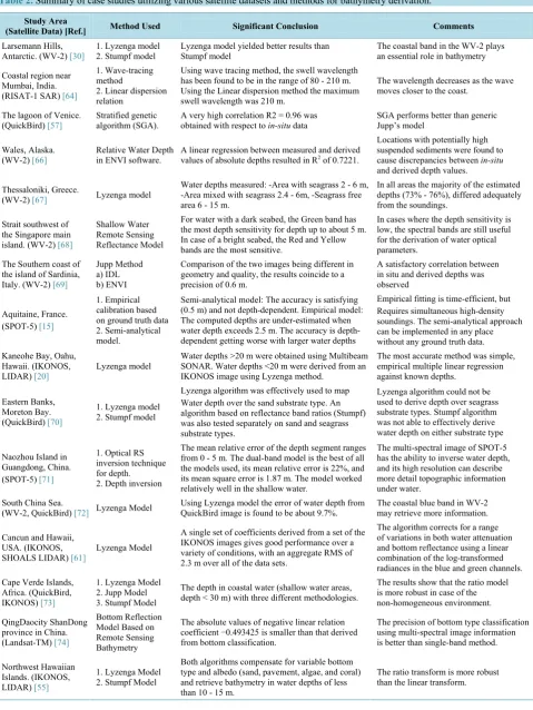
4. Review on Case Studies Employed for Bathymetry Derivation
As bathymetry derived from imagery is estimated rather than directly measured, it is worth discussing the influ-ence and impact of the algorithms used to model the depths. A number of different algorithms have been derived to determine bathymetry from imagery. For HS and MS imagery derived bathymetry, it is just as important to select the most appropriate algorithm, as it is to select the most suitable image sensor. Mobley [65] compared six common algorithms used to derive bathymetry. Few case studies are discussed for comparison of methods, models, algorithms, and types of data used for derivation of bathymetry (Table 2).
5. Summary and Discussion
The seafloor is one of the last mostly unexplored and most dynamic landscapes on the planet earth. Technologi-cal development for bathymetry derivation has progressed rapidly in the last century because of the advance-ment of techniques using acoustics, optics, and radar. More acoustic depth soundings are required to validate RS based models for the derivation of bathymetry in remote regions of the world (e.g. Southern Ocean, around An-tarctica, Arctic, etc.). The present review focuses mainly on techniques used for deriving the bathymetry, me-thods and technologies evolved for bathymetric derivation, and limitations and advantages of bathymetric algo-rithms. There are two broad ways in which RS methods for bathymetry derivation can be categorized: active RS/passive RS and non-imaging/imaging. The non-imaging LIDAR method is capable to detect elevations at sampled locations, but this method is not widely used for practical applications until recently because of tech-nical constraints. LIDAR method is capable to derive a large range of depths up to 70 m in clear open waters with an accuracy of ±15 cm [7]. Airborne LIDAR is appropriate for bathymetric mapping over relatively small geographical areas. LIDAR accuracy and applicability are additionally constrained by water turbidity. In com-parison, the passive optical imaging method is more flexible, because it can be implemented either analytically or empirically. Analytical modeling is complex to implement since it requires the input of in-situ measured pa-rameters related to the optical properties of water. Empirical modeling is much easier to implement, since it re-quires only a limited number of in-situ measurements at certain sampling spots. This implementation may pro-duce results which have similar accuracy to the analytical or semi-analytical implementations under certain cir-cumstances. The passive imaging methods are widely applicable to both shallow turbid coastal waters and open oceanic waters. It is just important to select the most appropriate bathymetric algorithm, as it is to select most suitable image sensors for an effective derivation of bathymetry. Each model or sensor has benefits and limita-tions. For most of the case studies, optical data, such as WV-2, QuickBird, SPOT, Landsat and IKONOS, have been used [15] [20] [30] [55] [57] [61] [66]-[85].
Table 2.Summary of case studies utilizing various satellite datasets and methods for bathymetry derivation. Study Area
(Satellite Data) [Ref.] Method Used Significant Conclusion Comments Larsemann Hills,
Antarctic. (WV-2) [30] 1. Lyzenga model 2. Stumpf model Lyzenga model yielded better results than Stumpf model The coastal band in the WV-2 plays an essential role in bathymetry Coastal region near
Mumbai, India. (RISAT-1 SAR) [64]
1. Wave-tracing method
2. Linear dispersion relation
Using wave tracing method, the swell wavelength has been found to be in the range of 80 - 210 m. Using the Linear dispersion method the maximum swell wavelength was 210 m.
The wavelength decreases as the wave moves closer to the coast.
The lagoon of Venice.
(QuickBird) [57] Stratified genetic algorithm (SGA). A very high correlation R2 = 0.96 was obtained with respect to in-situ data SGA performs better than generic Jupp’s model
Wales, Alaska.
(WV-2) [66] Relative Water Depth in ENVI software. A linear regression between measured and derived values of absolute depths resulted in R2 of 0.7221.
Locations with potentially high suspended sediments were found to cause discrepancies between in-situ and derived depth values. Thessaloniki, Greece.
(WV-2) [67] Lyzenga model
Water depths measured: -Area with seagrass 2 - 6 m, -Area mixed with seagrass 2.4 - 6m, -Seagrass free area6 - 15 m.
In all areas the majority of the estimated depths (73% - 76%), differed adequately from the soundings.
Strait southwest of the Singapore main island. (WV-2) [68]
Shallow Water Remote Sensing Reflectance Model
For water with a dark seabed, the Green band has the most depth sensitivity for depth up to about 5 m. In case of a bright seabed, the Red and Yellow bands are the most sensitive.
In cases where the depth sensitivity is low, the spectral bands are still useful for the derivation of water optical parameters.
The Southern coast of the island of Sardinia, Italy. (WV-2) [69]
Jupp Method a) IDL b) ENVI
Comparison of the two images being different in geometry and quality, the results coincide to a precision of 0.6 m.
A satisfactory correlation between in situ and derived depths was observed
Aquitaine, France. (SPOT-5) [15]
1. Empirical calibration based on ground truth data 2. Semi-analytical model.
Semi-analytical model: The accuracy is satisfying (0.5 m) and not depth-dependent. Empirical model: The computed depths are under-estimated when water depth exceeds 2.5 m. The accuracy is depth- dependent getting worse with larger water depths
Empirical fitting is time-efficient, but Requires simultaneous high-density soundings. The semi-analytical approach can be implemented in any place without any ground truth data. Kaneohe Bay, Oahu,
Hawaii. (IKONOS,
LIDAR) [20] Lyzenga model
Water depths >20 m were obtained using Multibeam SONAR. Water depths <20 m were derived from an IKONOS image using Lyzenga method.
The most accurate method was simple, empirical multiple linear regression against known depths.
Eastern Banks, Moreton Bay. (QuickBird) [70]
1. Lyzenga model 2. Stumpf model
Lyzenga algorithm was effectively used to map Water depth over the sand substrate type. An algorithm based on reflectance band ratios (Stumpf) was also tested separately on sand and seagrass substrate types.
Lyzenga algorithm could not be used to derive depth over seagrass substrate types. Stumpf algorithm was not able to effectively derive water depth on either substrate type
Naozhou Island in Guangdong, China. (SPOT-5) [71]
1. Optical RS inversion technique for depth. 2. Depth inversion
The mean relative error of the depth segment ranges from 0 - 5 m. The dual-band model is the best of all the models used, its mean relative error is 22%, and its mean square error is 1.87 m. The model worked relatively well in the shallow water.
The multi-spectral image of SPOT-5 has the ability to inverse water depth, and its high resolution can describe more detail topographic information under water.
South China Sea.
(WV-2, QuickBird) [72] Lyzenga Model Using Lyzenga model the error of water depth from QuickBird image is found to be about 9.7%. The coastal blue band in WV-2 may retrieve more information.
Cancun and Hawaii, USA. (IKONOS,
SHOALS LIDAR) [61] Lyzenga Model
A single set of coefficients derived from a set of the IKONOS images gives good performance over a variety of conditions, with an aggregate RMS of 2.3 m over all of the data sets.
The algorithm corrects for a range of variations in both water attenuation and bottom reflectance using a linear combination of the log-transformed radiances in the blue and green channels. Cape Verde Islands,
Africa. (QuickBird, IKONOS) [73]
1. Lyzenga Model 2. Jupp Model 3. Stumpf Model
The depth in coastal water (shallow water areas, depth < 30 m) with three different methodologies.
The results show that the ratio model is more robust in case of the non-homogeneous environment. QingDaocity ShanDong
province in China. (Landsat-TM) [74]
Bottom Reflection Model Based on Remote Sensing Bathymetry
The absolute values of negative linear relation coefficient −0.493425 is smaller than that derived from bottom classification.
The precision of bottom type classification using multi-spectral image information is better than single-band method.
Northwest Hawaiian Islands. (IKONOS, LIDAR) [55]
1. Lyzenga Model 2. Stumpf Model
Both algorithms compensate for variable bottom type and albedo (sand, pavement, algae, and coral) and retrieve bathymetry in water depths of less than 10 - 15 m.
of the algorithms (Linear/Lyzenga and Ratio/Stumpf) are found to be superior to accurately determine the shal-low depth in highly turbid waters given sufficiently representative training data sets. The ratio transform method or Stumpf model has less number of empirical coefficients which makes the method simple to use and more sta-ble over broad geographic areas. The ratio model is more robust in case of the non-homogenous environment. The ratio transform has limitations relative to the linear transform, particularly in an increased level of noise. On the other hand, Lyzenga linear band model employs two or more bands, which allows separation of variations in depth from variations in bottom albedo, but compensation for turbidity. Retrieval of bathymetry under restrictive environmental conditions is limited. The linear band algorithm modified from Lyzenga et al. [61] can provide slightly better results than Stumpf model using WV-2 data. The additional 4 spectral bands provided by the WV- 2 have been found to be improved the linear band model marginally. A classification using band instead of raw band values achieved results comparable to the linear band algorithm. Although its data input requirements are the same as the more accurate band classification, its lower computation requirements may make it attractive af-ter further validation. The linear ratio algorithm developed by Stumpf et al. [55] may prove completely ineffec-tive in waters where turbidity is the predominant factor defining attenuation in the water column. In order to achieve better results using the linear ratio model, ground reference or in-situ datasets should be considered to represent a wide range of variance in bottom type and water column properties with statistically significant sam-ple sizes at different depths.
Acknowledgements
We acknowledge Dr. S. Rajan, Director, NCAOR for his encouragement and motivation of this research. We acknowledge Dr. T. P. Singh (Director, SIT), Dr. Kanchan Khare (HOD, Department of Civil Engineering, SIT), Prof Sagar Kolekar (SIT), and Prof. Rushikesh Kulkarni (SIT), for their cooperation. We also thank Ms. Prachi Vaidya, India for her constructive comments on the draft version of the manuscript. This is NCAOR contribu-tion No. 17/2015.
References
[1] Tomanka, K. (2014) Hydrography: More than Nautical Charts. National Oceanic and Atmospheric Administration (NOAA). http://www.nauticalcharts.noaa.gov/staff/news/2014/docs/135572_NOAA_Hydro-epubP7.pdf
[2] Clay, C. (1998) Fundamentals of Acoustical Oceanography. Academic Press, New York. http://www.waterencyclopedia.com/Oc-Po/Ocean-Floor-Bathymetry.html#ixzz397YTS472
[3] Kearns, T.A., Breman, J., Barry, W.E., Taylor Martin, C., Meaden, G., Vaz, S., et al. (2010) Bathymetry—The Art and Science of Seafloor Modelling for Modern Applications, 1-36.
http://downloads2.esri.com/ESRIpress/images/169/OGLOBE_toc.pdf [4] Tronvig, K.A. (2005) Near-Shore Bathymetry. Hydro International, 9, 24-25.
http://www.hydro-international.com/issues/articles/id484-Nearshore_Bathymetry.html
[5] Sichoix, L. and Bonneville, A. (1996) Prediction of Bathymetry in French Polynesia Constrained by Shipboard Data.
GeophysicalResearchLetters, 23, 2469-2472. http://dx.doi.org/10.1029/96gl02122
[6] Roberts, A.C.B. and Anderson, .J.M. (1999) Shallow Water Bathymetry Using Integrated Airborne Multi-Spectral Re-mote Sensing. InternationalJournalofRemoteSensing, 20, 497-510. http://dx.doi.org/10.1080/014311699213299 [7] Gao, J. (2009) Bathymetric Mapping by Means of Remote Sensing: Methods, Accuracy and Limitations. Progress in
Physical Geography, 33, 103-116. http://dx.doi.org/10.1177/0309133309105657
[8] Flener, C., Lotsari, E., Alho, P. and Käyhkö, J. (2012) Comparison of Empirical and Theoretical Remote Sensing Based Bathymetry Models in River Environments. RiverResearchandApplications, 28, 118-133.
[9] Dixon, T.H., Naraghi,M., McNutt, M.K. and Smith, S.M. (1983) Bathymetric Prediction from Seasat Altimeter Data.
Journal of Geophysical Research, 88, 1563-1571. http://dx.doi.org/10.1029/jc088ic03p01563
[10] Smith, W.H.F. and Sandwell, D.T. (1994) Bathymetric Prediction from Dense Satellite Altimetry and Sparse Ship-board Bathymetry. Journal of Geophysical Research, 99, 803-821.
[11] Vogelzang, J., Wensink, G.J., De Loop, G.P., Peters, H.C. and Pouwels, H. (1943) Sea Bottom Topography with X-Band SLAR: The Relation between Radar Imagery and Bathymetry.InternationalJournalofRemoteSensing, 13, 1943-1958. http://dx.doi.org/10.1080/01431169208904242
2998. http://dx.doi.org/10.1080/01431160116928
[13] Spitzer, D. and Dirks, R.W.J. (1986) Classification of Bottom Composition and Bathymetry of Shallow Waters by Pas-sive Remote Sensing. Proceedingsofthe 7thISPRS CommissionVII Symposium onRemoteSensing forResources DevelopmentandEnvironmentalManagement, 2, 775-777.
[14] Lyzenga, D.R. (1998) Passive Remote Sensing Techniques for Mapping Water Depth and Bottom Features. Applied Optics, 17, 379-83. http://dx.doi.org/10.1364/AO.17.000379
[15] Lafon, V., Froidefond, J.M, Lahe, F.T. and Castaing, P. (2002) SPOT Shallow Water Bathymetry of a Moderately Turbid Tidal Inlet Based on Field Measurements.RemoteSensingofEnvironment, 81, 136-148.
http://dx.doi.org/10.1016/S0034-4257(01)00340-6
[16] Ji, W., Civco, D.L. and Kennard, W.C. (1992) Satellite Remote Bathymetry: A New Mechanisms for Modelling. Pho-togrammetricEngineeringandRemoteSensing, 58, 545-549.
[17] Ibrahim, M. and Cracknell, A.P. (1990) Bathymetry Using Landsat MSS Data of Penang Island in Malaysia. Interna-tionalJournalofRemoteSensing, 11, 557-559. http://dx.doi.org/10.1080/01431169008955040
[18] Bierwirth, P.N., Lee, T.J. and Burne, R.V. (1993) Shallow Sea-Floor Reflectance and Water Depth Derived by Un-mixing Multispectral Imagery. PhotogrammetricEngineeringandRemoteSensing, 59, 331-338.
[19] Minghelli-Roman, A., Goreac, A., Mathieu, S., Spigai, M. and Gouton, P. (2009) Comparison of Bathymetric Estima-tion Using Different Satellite Images in Coastal Sea Water. InternationalJournalofRemoteSensing, 30, 5737-5750. http://dx.doi.org/10.1080/01431160902729580
[20] Hochberg, E.J., Atkinson, M.J. and Andréfouët, S. (2003) Spectral Reflectance of Coral Reef Bottom-Types World-wide and Implications for Coral Reef Remote Sensing. RemoteSensingofEnvironment, 85, 159-173.
http://dx.doi.org/10.1016/S0034-4257(02)00201-8
[21] Capolsini, P., Andréfouët, S., Rion, S.C. and Payri, C. (2003) A Comparison of Landsat ETM+, SPOT HRV, Ikonos, ASTER and Airborne MASTER Data for Coral Reef Habitat Mapping in South Pacific Islands. CanadianJournalof RemoteSensing, 29, 187-200. http://dx.doi.org/10.5589/m02-088
[22] Collet, C., Provost, J.-N., Rostaing, P., Perez, P. and Bouthemy, P. (2000) SPOT Satellite Data Analysis for Bathyme-tric Mapping. ProceedingsoftheInternationalConferenceonImageProcessing, 3, 464-467.
http://dx.doi.org/10.1109/icip.2000.899440
[23] Khoury, M. and Ellis, G. (2009) Digitalglobe’s Advanced Satellite Constellation, 8-Band High-Resolution Imagery & Collection Optimisation by European Space Imaging, Member of the Worldview Global Alliance. Proceedingsofthe
15thGeoCAPAnnualConference, Taormina, 18-20 November 2009, 18-26.
[24] Jawak, S.D. and Luis, A.J. (2014) A Semiautomatic Extraction of Antarctic Lake Features Using WorldView-2 Im-agery. PhotogrammetricEngineering & RemoteSensing, 80, 939-952. http://dx.doi.org/10.14358/PERS.80.10.939 [25] Jawak, S.D. and Luis, A.J. (2013) Very-High Resolution Remotely Sensed Satellite Data for Improved Land Cover
Extraction of Larsemann Hills, East Antarctica. JournalofAppliedRemoteSensing, 7, Article ID: 073460. http://dx.doi.org/10.1117/1.JRS.7.073460
[26] Jawak, S.D. and Luis, A.J. (2013) A Comprehensive Evaluation of PAN-Sharpening Algorithms Coupled with Resam-pling Methods for Image Synthesis of Very High Resolution Remotely Sensed Satellite Data. Advances inRemote Sensing, 2, 332-344. http://dx.doi.org/10.4236/ars.2013.24036
[27] Jawak, S.D. and Luis, A.J. (2013) Improved Land Covers Mapping Using High Resolution Multiangle 8-Band WorldView-2 Satellite Remote Sensing Data. JournalofAppliedRemoteSensing, 7, Article ID: 073573.
http://dx.doi.org/10.1117/1.jrs.7.073573
[28] Jawak, S.D. and Luis, A.J. (2013) A Spectral Index Ratio-Based Antarctic Land-Cover Mapping Using Hyperspatial 8-Band WorldView-2 Imagery. PolarScience, 7, 18-38. http://dx.doi.org/10.1016/j.polar.2012.12.002
[29] Jawak, S.D. and Luis, A.J. (2012) Synergistic Use of Multitemporal RAMP, ICESat and GPS to Construct an Accurate DEM of the Larsemann Hills Region, Antarctica. AdvancesinSpaceResearch, 50, 457-470.
http://dx.doi.org/10.1016/j.asr.2012.05.004
[30] Jawak, S.D. and Luis, A.J. (2015) Spectral Information Analysis for the Semiautomatic Derivation of Shallow Lake Bathymetry Using High-Resolution Multispectral Imagery: A Case Study of Antarctic Coastal Oasis. International ConferenceonWaterResources, CoastalandOceanEngineering (ICWRCOE 2015), Aquatic Procedia, 4, 1331-1338. http://dx.doi.org/10.1016/j.aqpro.2015.02.173
[31] The Benefits of the Eight Spectral Bands of WorldView-2, WP-8SPEC Rev 01/13. https://www.digitalglobe.com/sites/default/files/DG-8SPECTRAL-WP_0.pdf
Depart-ment of Climate Change and Energy Efficiency.
[33] Bagheri, S., Stein, M. and Dios, R. (1998) Utility of Hyperspectral Data for Bathymetric Mapping in a Turbid Estuary.
InternationalJournalofRemoteSensing, 19, 1179-1188. http://dx.doi.org/10.1080/014311698215676
[34] Kutser, T. and Jupp, D.L.B. (2002) Mapping Coral Reef Benthic Habitat with a Hyperspectral Space Borne Sensor.
ProceedingsofOceanOptics XVI, Santa Fe, 18-22.
[35] Hickman, G.D. and Hogg, J.E. (1969) Application of an Airborne Pulsed Laser for Near Shore Bathymetric Measure-ments. RemoteSensingofEnvironment, 1, 47-58. http://dx.doi.org/10.1016/S0034-4257(69)90088-1
[36] Lyzenga, D.R. (1985) Shallow-Water Bathymetry Using Combined Lidar and Passive Multispectral Scanner Data. In-ternationalJournalofRemoteSensing, 6, 115-125. http://dx.doi.org/10.1080/01431168508948428
[37] Finkl, C.W., Benedet, L. and Andrews, J.L. (2005) Submarine Geomorphology of the Continental Shelf off Southeast Florida Based on Interpretation of Airborne Laser Bathymetry. JournalofCoastalResearch, 21, 1178-1190.
http://dx.doi.org/10.2112/05A-0021.1
[38] Guenther, G.C., Brooks, M.W. and Larocque, P.E. (2000) New Capabilities of the “SHOALS” Airborne Lidar Bathy-meter. RemoteSensingofEnvironment, 73, 247-55. http://dx.doi.org/10.1016/S0034-4257(00)00099-7
[39] Mallet, C. and Bretar, F. (2009) Full-Waveform Topographic Lidar: State-of-the-Art. ISPRSJournalof Photogramme-tryandRemoteSensing, 64, 1-16. http://dx.doi.org/10.1016/j.isprsjprs.2008.09.007
[40] Wang, C.-K. and Philpot, W.D. (2007) Using Airborne Bathymetric Lidar to Detect Bottom Type Variation in Shallow Waters. RemoteSensingofEnvironment, 106,123-35. http://dx.doi.org/10.1016/j.rse.2006.08.003
[41] Abbot, R.H., Lane, D.W., Sinclair, M.J. and Spruing, T.A. (1996) Lasers Chart the Waters of Australia’s Great Barrier Reef. ProceedingsoftheSocietyofPhotographicInstrumentationEngineers, 2964, 72-90.
[42] Huang, W.G., Fu, B., Zhou, C.B., Yang, J.S., Shi, A.Q. and Li, D.L. (2001) Shallow Water Bathymetric Surveys by Spaceborne Synthetic Aperture Radar. IEEEInternational GeoscienceandRemoteSensingSymposium, Vol. 6, Sydney, 9-13 July 2001, 2810-2812. http://dx.doi.org/10.1109/igarss.2001.978171
[43] Alphers, W. and Hennings, L. (1984) A Theory of the Imaging Mechanism of Underwater Bottom Topography by Real and Synthetic Aperture Radar. JournalofGeophysicalResearch, 89, 10529-10546.
[44] Vogelzang, J., Wensink, G.J., De Loor, G.P., Peters, H.C., Pouwels, H. and Gein, W.A. (1989) Sea Bottom Topogra-phy with X Band SLAR. BCRSReport, BCRS-89-25.
[45] Robinson, I.S. (2004) Measuring the Oceans from Space: The Principles and Methods of Satellite Oceanography. Praxis Publishing, Chichester, 720.
[46] Calkoen, C.J., Kooi, M.W.A, Hesselmans, G.H.F.M. and Wensink, G.J. (1993) The Imaging of Sea Bottom Topogra-phy with Polarmetric P-, L-, and C-Band SAR. Report BCRS Project 2.1/AO-02, Netherlands Remote Sensing Board, Delft.
[47] Smith, W.H.F. and Sandwell, D.T. (1997) Global Sea Floor Topography from Satellite Altimetry and Ship Depth Soundings. Science, 277, 1956-1962. http://dx.doi.org/10.1126/science.277.5334.1956
[48] Vogt, P.R. and Jung, W.Y. (1991) Satellite Radar Altimetry Aids Seafloor Mapping. EOS Transactions, American GeophysicalUnion, 72, 465-469.
[49] Jung, W.Y. and Vogt, P.R. (1992) Predicting Bathymetry from Geosat-ERM and Shipborne Profiles in the South At-lantic Ocean. Tectonopliysics, 210, 235-253. http://dx.doi.org/10.1016/0040-1951(92)90324-Y
[50] Baudry, N., Diament, M. and Albouy, Y. (1987) Precise Location of in Surveyed Seamounts in the Australian Archip-lago Using SEASAT Data. Geophysical Journal International, 89, 869-888.
http://dx.doi.org/10.1111/j.1365-246X.1987.tb05199.x
[51] Craig, C.H. and Sandwell, D.T. (1988) Global Distribution of Seamounts from Seasat Profiles. Journal of Geophysical Research, 93, 10408-10420. http://dx.doi.org/10.1029/JB093iB09p10408
[52] Baudry, N. and Calmant, S. (1991) 3D Modelling of Seamount Topography From Satellite Altimetry. Geophysical Re-search Letters, 18, 1143-1146.
[53] Calmant, S. (1994) Seamount Topography by Least-Squares Inversion of Altimetric Geoid Heights and Shipborne Pro-files of Bathymetry and /or Gravity Anomalies. Geophysical Journal International, 119, 428-452.
[54] Calmant, S. and Baudry, N. (1996) Modelling Bathymetry by Inverting Satellite Altimetry Data: A Review. Marine Geophysical Researches, 18, 123-134.
[55] Stumpf, R.P., Holderied K. and Sinclair, M. (2003) Determination of Water Depth with High Resolution Satellite Im-agery over Variable Bottom Types. Limnology and Oceanography, 48, 547-556.
http://dx.doi.org/10.4319/lo.2003.48.1_part_2.0547
Proceedings of the SymposiumonRemoteSensingoftheCoastalZone, Gold Coast, IV2(1)-IV2(19).
[57] Gianinetto, M. and Lechi, G. (2013) A DNA Algorithm for the Batimetric Mapping in the Lagoon of Venice Using Quick Bird Multispectral Data. XXth ISPRS Congress on Geo-Imagery Bridging Continents, The International Archive of the Photogrammetry, Remote Sensing and Spatial Information Sciences, XXXV(B), 94-99.
http://citeseerx.ist.psu.edu/viewdoc/summary?doi=10.1.1.158.8724
[58] Baban, S.M.J. (1993) The Evaluation of Different Algorithms for Bathymetric Charting of Lakes Using Landsat Im-agery. InternationalJournalofRemoteSensing, 14, 2263-2273. http://dx.doi.org/10.1080/01431169308954035 [59] Campbell, J.B. (1996) Introduction to Remote Sensing. 2nd Edition, The Guilford Press, New York.
[60] Lyzenga, D.R. (1978) Passive Remote Sensing Techniques for Mapping Water Depth and Bottom Features. Applied Optics, 17, 379-383. http://dx.doi.org/10.1364/AO.17.000379
[61] Lyzenga, D.R., Malinas, N.P. and Tanis, F.J. (2006) Multispectral Bathymetry Using a Simple Physically Based Algo-rithm. IEEETransactionsonGeosciencesandRemoteSensing, 44, 2251-2259.
http://dx.doi.org/10.1109/TGRS.2006.872909
[62] Feurer, D., Puech, C., .Bailly, J.S. and Viau, A. (2006) Bathymetric Measurement of Rivers by Remote Sensing Tech-niques: A Review. InternationalConferenceonRiverineHydroecology: AdvancesinResearchApplications, Stirling, 14-18 August 2006.
[63] Allouis, T., Bailly, J.S. and Feurer, D. (2010) Assessing Water Surface Effects on LiDAR Bathymetry Measurements in Very Shallow Rivers: A Theoretical Study. 2nd ESA Space for Hydrology Workshop, Geneva, 12-14 November 2007, 12-14.
[64] Mishra, M.K., Ganguly, D., Chauhan, P. and Ajai (2014) Estimation of Coastal Bathymetry Using RISAT-1 C-Band Microwave SAR Data. IEEEGeosciencesandRemoteSensingLetters, 11, 671-675.
http://dx.doi.org/10.1109/LGRS.2013.2274475
[65] Mobley, C.D. (2009) Algorithm Comparison for Shallow-Water Remote Sensing. OfficeofNavalResearchReport, 6. http://handle.dtic.mil/100.2/ADA541078
[66] Smith, J.R., Kinsman, N.E.M. and Misra, D. (2013) Using WorldView-2 Multispectral Bands for Shallow Water Ba-thymetric Survey near Wales, Alaska (Poster). American Society ofPhotogrammetry and Remote Sensing Annual Meeting, Baltimore.
[67] Doxani, G., Papadopoulou, M., Lafazani, P., Pikridas, C. and Tsakiri-Strati, M. (2012) Shallow-Water Bathymetry over Variable Bottom Types Using Multispectral Worldview-2 Image. International Archives of the Photogrammetry,
Remote Sensing and Spatial Information Sciences, XXXIX-B8, 159-164. http://dx.doi.org/10.5194/isprsarchives-XXXIX-B8-159-2012
[68] Liew, S.C., Chang, C.W. and Kwoh, L.K. (2012) Sensitivity Analysis in the Retrieval of Turbid Coastal Water Bathy-metry Using WorldView-2 Satellite Data. International Archives of the Photogrammetry, Remote Sensing and Spatial Information Sciences, XXXIX-B7, 13-16.
[69] Deidda, M. and Sanna, G. (2012) Bathymetric Extraction Using WorldView-2 High Resolution Images. nternational Archives of the Photogrammetry, Remote Sensing and Spatial Information Sciences, XXXIX-B8, 153-157.
http://dx.doi.org/10.5194/isprsarchives-XXXIX-B8-153-2012
[70] Lyons, M., Phinn, S. and Roelfsema, C. (2011) Integrating QuickBird Multi-Spectral Satellite and Field Data: Mapping Bathymetry, Seagrass Cover, Seagrass Species and Change in Moreton Bay, Australia in 2004 and 2007. Remote Sensing, 3, 42-64. http://dx.doi.org/10.3390/rs3010042
[71] Liu, S., Zhang, J. and Ma, Y. (2010) Bathymetric Ability of SPOT-5 Multi-Spectral Image in Shallow Coastal Water. 18th International Conference on Geoinformatics, Beijing, 18-20 June 2010, 1-5.
http://dx.doi.org/10.1109/geoinformatics.2010.5567951
[72] Ho, C.R., Huang, S.J. and Kuo, N.J. (2009) Bathymetric Mapping around Islands in the South China Sea with Quick Bird and WorldView-2 Imagery. Oceans 2009-Europe.
[73] Pennucci, G., Grasso, R. and Trees, C. (2006) Bathymetry Estimation from High-Resolution Satellite Images. http://geos2.nurc.nato.int/mreaconf/posters/151_Pennucci.pdf
[74] Qing, D.W., Lei, Y., Qin, P., Hong, Z.Y. and Li, M.W. (1996) PCA Based on Bottom Classification Applied in Re-mote Sensing Bathymetry of Shallow Seawater. http://www.isprs.org/proceedings/XXXVI/part7/PDF/196.pdf [75] Jawak, S.D., Luis, A.J., Panditrao, S.N., Khopkar, P.S. and Jadhav, P.S. (2013) Advancement in Landcover
Classifica-tion Using Very High ResoluClassifica-tion Remotely Sensed 8-Band WorldView-2 Satellite Data. InternationalJournalofEarth SciencesandEngineering, 6, 1742-1749.
http://dx.doi.org/10.1016/j.aqpro.2015.02.018
[77] Jawak, S.D., Raut, D.A. and Luis, A.J. (2015) Iterative Spectral Index Ratio Exploration for Object-Based Image Analysis of Antarctic Coastal Oasis Using High Resolution Satellite Remote Sensing Data. AquaticProcedia, 4, 157- 164. http://dx.doi.org/10.1016/j.aqpro.2015.02.022
[78] Jawak, S.D., Panditrao, S.N., Luis, A.J. (2014) Enhanced Urban Landcover Classification for Operational Change De-tection Study Using Very High Resolution Remote Sensing Data. InternationalArchivesofthePhotogrammetry, Re-moteSensingandSpatialInformationSciences, XL-8, 773-779.
http://dx.doi.org/10.5194/isprsarchives-XL-8-773-2014
[79] Jawak, S.D., Khopkar, P.S., Jadhav, S.P. and Luis, A.J. (2013) Customization of Normalized Difference Snow Index for Extraction of Snow Cover from Cryospheric Surface using WorldView-2 Data. ProceedingsofAGSEInternational Conference, CEPT University, Ahmedabad, India, 16-19 December 2013, 391-398.
[80] Jawak, S.D. and Luis, A.J. (2012) WorldView-2 Satellite Remote Sensing Data for Polar Geospatial Information Min-ing of Larsemann Hills, East Antarctica. Proceedingsof 11thPacific (Pan) OceanRemoteSensingConference (PORSEC), Kochi, 5-9 November 2012, ID: PORSEC2012-24-00006.
[81] Jawak, S.D. and Luis, A.J. (2011) Applications of WorldView-2 Satellite Data for Extraction of Polar Spatial Informa-tion and DEM of Larsemann Hills, East Antarctica. InternationalConferenceonFuzzySystemsandNeuralComputing
(FSNC 2011), 3, 148-151.
[82] Jawak, S.D. and Luis, A.J. (2014) Spectral Bands of WorldView-2 Satellite Remote Sensing Data for Semiautomatic Land Cover Extraction in the Antarctic Environment. XXXIII SCAR and 6thOpen Science Conference, Auckland, 25-28 August 2014.
[83] Jawak, S.D. and Luis, A.J. (2014) A Novel Set of Normalized Difference Snow/Ice Index ratios for Extraction of Snow Cover from the Antarctic Environment Using Very High Resolution Satellite Data. XXXIII SCAR and 6th Open ScienceConference, Auckland, 25-28 August 2014.
[84] Jawak, S.D. and Luis, A.J. (2012) Hyperspatial WorldView-2 Satellite Remote Sensing Data for Polar Geospatial In-formation Mining of Larsemann Hills, East Antarctica. XXXII SCAR and 5thOpenScienceConference (OSC), Port-land, 13-25 July 2012.
![Table 1. Types of non-imaging and imaging systems with their strengths and limitations (source: modified from Gao [7])](https://thumb-us.123doks.com/thumbv2/123dok_us/8108013.790046/3.595.88.537.101.401/table-types-imaging-imaging-systems-strengths-limitations-modified.webp)