ii
DESIGN OF MICROSTRIP PATCH ANTENNA FOR IEEE 802.16-2004 APPLICATIONS
EHAB ESAM DAWOOD AL-RAWACHY
A thesis submitted in
Fulfillment of the requirement for the award of the Degree of Master of Electrical Engineering
Faculty of Electrical and Electronic Engineering Universiti Tun Hussein Onn Malaysia
vi
ABSTRACT
This thesis presents microstrip patch antenna IEEE 802.16-2004 standards for microwave applications and WiMax. Narrow bandwidth (BW) is the main defect of microstrip patch antenna in wireless communication. The bandwidth can be
improved by increasing the substrate thickness, and using air as substrate with low dielectric constant. The antennas were fabricated using FR4 board. Two types of microstrip antenna were used, the first was a single microstrip patch antenna and the second was using an air-gap technique as the dielectric between two antenna boards. The spacer of the air-gap has thickness of 2mm. It was made of wood to separate between the two boards. The transmission line model was used to get the
approximate dimension for the design. Different parameters were obtained depending on the simulation and measurement. The Computer Simulations Technology (CST) software was used to simulate the design and the measurement was executed by Vector Network Analyzer (VNA). The two designs were compared to each other and found that some improvements were obtained on the air-gap
technique. The bandwidth was improved by 4.51 % with air-gap technique and only 1.02 % with the single patch antenna.
vii
Abstrak
Tesis ini mempersebahka microstrip patches antenna untuk standard IEEE 802.16-2004 bagi kegunaan mikrogelombang dan WiMax. Microstrip patches antenna menghadapi masalah lebar jalur yang sempit dalam komunikasi wayarles. Lebar jalur tersebut boleh ditambah baik dengan menambah ketebalan substrate dan menggunakan udara (pemalar dielektrik, 1) sebagai substrate. Kedua-dua antenna ini dibuat menggunakan papan litar tercetak FR4. Dua jenis microstrip patch antenna telah digunakan, pertama microstrip patch antenna tunggal, dan yang kedua menggunakan teknik sela-udara sebagai dielektrik yang memisahkan antara dua papan. Sela udara mempunyai ketebalan sebanyak 2 mm yang dibuat menggunakan kayu sebagai pemisah antara dua papan. Model line penghantaran digunakan untuk mendapatkan dimensi anggaran untuk merekabentuk parameter yang berbeza
bergantung pada simulasi dan pengukuran. Perisian Simulasi Komputer Teknologi (CST) digunakan untuk mensimulasi rekabentuk sementara pengukuran
dilaksanakan dengan rangkaian Vector Network Analyzer (VNA). Daripada
viii
CONTENTS
DESIGN OF MPA FOR IEEE 802.16-2004 APPLICATIONS ii
ACKNOWLEDGEMENT v
ABSTRACT vi
CONTENTS viii
LIST OF TABLES xviii
LIST OF FIGURES xix
LIST OF SYMBOLS AND ACRONYMS xxii
LIST OF APPENDICES xxiv
ix
1.1 Overview 1
1.2 Antenna 1
1.3 Microstrip antenna advantage and limitation 3
1.4 Problem Statements 4
1.5 Project Objectives 4
1.6 Project Scopes 5
CHAPTER 2 LITERATURE REVIEW 7
2.1 History 7
2.2 Basic Communication System 9
2.3 The Cellular Concept 10
2.4 Different Mobiles Generation 11
x
2.4.2 Second Generation System 12
2.4.2.1 GSM 12
2.4.2.2 Interim Standard (IS-136) 12
2.4.2.3 Personal Digital Cellular (PDC) 13
2.4.2.4 Interim Standard 95 (IS-95) 13
2.4.3 Third generation system 13
2.4.4 Forth generation system and beyond 14
2.5 Wireless local loop (WLL) 15
2.5.1 WiFi (802.11) 15
2.5.1.1 IEEE 802.11b 15
2.5.1.2 IEEE 802.11g 15
xi
2.5.1.4 IEEE 802.11n 16
2.6 Bluetooth 16
2.7 IEEE 802.16 17
2.7.1 IEEE 802.16d 18
2.7.2 IEEE 802.16e 18
2.8 Importance of Antenna in Wireless System 19
2.9 Antennas Types 20
2.9.1 Wire Antennas 20
2.9.2 Aperture Antennas 21
2.9.3 Microstrip antenna 22
2.9.4 Array antenna 22
xii
2.9.6 Lens Antennas 24
2.10 Antenna characteristics 24
2.10.1 The transmitting antenna 25
2.10.2 Field region of antennas 25
2.10.2.1 Reactive Near Field Region 26
2.10.2.2 Radiating Near Field Region (Fresnel Region) 26
2.10.2.3 Far Field Region 26
2.10.3 Fundamental parameters 27
2.10.3.1 Radiation pattern 27
2.10.3.2 Directivity 28
2.10.3.3 Input impedance 29
xiii
2.10.3.5 Antenna Efficiency 30
2.10.3.6 Antenna Gain 30
2.10.3.7 Polarization 31
2.10.3.8 Q-factor 34
2.10.3.9 Bandwidth (BW) 34
CHAPTER 3 METHODOLOGY 35
3.1 Microstrip Antenna 35
3.2 Project Methodology 36
3.2.1 Design of Microstrip patch Antenna (MPA) 37
3.3 Surface Waves 38
3.4 Feeding Methods 39
xiv
3.4.2 Coaxial Feed 40
3.4.3 Aperture Coupled Feed 41
3.4.4 Proximity coupled Feed 42
3.5 Method of Analysis 43
3.5.1 Transmission Line Model 43
3.6 Patch Antenna Design 45
3.6.1 FR4 Substrate Material 45
3.6.2 CST microwave studio 47
3.6.2.1 Installation Requirements 48
3.6.3 CST Microwave Studio Step Design 48
3.6.3.1 Select Template 49
xv
3.6.3.3 Model the Coaxial Feed 53
3.6.3.4 Common Solver Settings 54
CHAPTER 4 Designs, Simulation, Fabrication and Measurement Result 57
4.1 Introduction 57
4.2 FR4 Substrate Dimension 58
4.3 Calculations for Patch Antenna Dimension 58
4.3.1 First Case (Single FR4 board) as Substrate Material 59
4.3.2 Second Case (air-gap with two FR4 Boards) as Substrate 60
4.4 Scattering parameters 62
4.5 Simulations Result 63
4.5.1 Simulation Result of Single Patch Antenna without Air-gap 63
xvi
4.5.1.2 2D Results 65
4.5.2 Simulation Result of Patch Antenna with Air-gap 66
4.5.2.1 1D Results 67
4.5.2.2 2D Results 68
4.6 Fabrications process 69
4.6.1 UV Exposure 71
4.6.2 Developing 72
4.6.3 Etching 73
4.6.4 Stripping 74
4.6.5 PCB Cutter Machine 75
4.6.6 Drilling the Location of Coax Line 76
xvii
4.7 Vector Network Analyzer (VNA) 78
4.7.1 Calibration the Vector Network Analyzer (VNA) 78
4.7.2 Connect MPA with Air-gap by VNA for Measurement 79
4.8 Measurement and Result 80
4.8.1 Smith Chart 81
4.8.2 Comparison of Simulated and Measured Results 82
4.9 Conclusion 84
REFERENCES 85
xviii
LIST OF TABLES
2.1: Simple timeline in wireless technologies evolution 8 2.2: Define some of the various 802.16 specifications 17 2.3: The different 802.16 specification inside different bands 18 2.4: Comparison of different 802.16 standards 19 4.1: Measured microstrip patch antenna with air-gap technique 80 4.2: The smith chart parameter 81 4.3: Compare the result between the simulation and 82
xix
LIST OF FIGURES
1.1: Microstrip patch antenna (MPA) 2
1.2: Different types of patches 3
2.1: Block diagram of digital communication system 9 2.2: Frequency reuse in cellular networks 10
2.3: Antenna is transition device 20
2.4: Wire antenna configurations 21
2.5: Aperture antenna configurations 21
2.6: Microstrip patch antenna 22
2.7: Typical array antennas 23
2.8: Typical reflector antennas 23
2.9: Typical lens antennas 24
2.10: Transmit antenna rcl equivalent circuit 25
2.11: Field region of an antenna 27
2.12: Radiation Lobes and bandwidths of an antenna pattern 28 2.13: Transmission line of antenna in transmitting mode 29
2.14: Linear polarization 32
2.15: Circular polarization 32
2.16: Elliptical polarization 33
3.1: Geometry of microstrip patch antenna(MPA) 36 3.2: Flow chart for collect the information and writing thesis 36
3.3: Design methodology 37
3.4: Microstrip feed line 40
3.5: Coaxial feed 41
3.6: Aperture coupled feed 41
3.7: Proximity coupled feed 41
xx 3.10: FR4 substrate with air separation 46 3.11: Spacer between the substrate dual boards 47
3.12: Supa glue 47
3.13: Structure of patch antenna with air-gap 49
3.14: CST microwave studio project 49
3.15: Antenna template 50
3.16: Creation brick 50
3.17 The first substrate creation 51
3.18: The air-gap with two layers substrate 51 3.19: Pick face tools 51
3.20: Extrude Tool 52
3.21: Dual patch antenna 53
3.22: Coaxial feed 53
3.23: Wave guide port excite port using picke face 54
3.24: Waveguid port 54
3.25: Frequency range 55
3.26: Boundary conditions menu 55
3.27: Patch antenna with boundary conditions 56
3.28: Farfield monitor 56
4.1: Dimensions of FR4 PCB used as substrate material 58 4.2: Design location of the coax line feed. 61 4.3: Structure of design and dimension for air-gap 62
4.4: Simulation of single FR4 PCB 63
4.5: Port signal for single FR4 PCB 64 4.6: Simulated resonant frequency and S11 using FR4 only 64 4.7: Simulated bandwidth (BW) of MPA using FR4 only 65 4.8: Input impedance and coaxial mode 65
4.9: Simulate MPA with air-gap 66 4.10: Port signal for MPA using air-gap 67 4.11: Simulated resonant frequency and S11 with air-gap 67 4.12: Simulated BW of MPA using air-gap 68 4.13: Input impedance and coaxial mode for MPA of air-gap 68 4.14: Flow chart for fabrication process 69
xxi
4.16: Fixing dry film on PCB 70
4.17: UV exposure machine 71
4.18: The FR4 PCB after exposed to UV light 71
4.19: Removing the transparent layer 72
4.20: Developing machine 72
4.22: Etching process 73
4.23: Stripping Machine 74 4.24: The FR4 board after stripping process 74 4.25: PCB cutter machine 75
4.26: MPA design 75 4.27: Drilling 76 4.28: SMA PCB connector 76 4.29: SMA connector soldered with FR4 PCB 77 4.30: Microstrip patch antenna with air-gap 77 4.31: The vector network analyzer (VNA) device 78 4.32: Calibration of VNA 79 4.33: MPA connected with VNA 80
4.34: S11 measurement 81 4.35: Smith chart of impedance 82
4.36: Compare between measurement and simulations 83 with air-gap and without air-gap for MPA
xxii
LIST OF SYMBOLS AND ACRONYMS
IEEE - Institute of Electrical and Electronics Engineers WIMAX - Worldwide Interoperability for Microwave Access
WLAN - Wireless LAN
GHz - Giga Hertz
KHz - Kilo Hertz
FR4 - Flame Retardant woven glass reinforced epoxy resin
BW - Bandwidth
Q-factor - Quality factor
CST - Computer Simulation Technology
1G - first Generation
2G - Second Generation
3G - Third Generation
4G - Fourth Generation
Mbit/s - Megabit/Second
A-D - Analogue-Digital
FM - Frequency Modulation
AMPS - Advanced Mobile Phone Service TACS - Total Access Communication System TDMA - Time Division Multiple Access CDMA - Code Division Multiple Access GSM - Global System for Mobil
IS - Interim Standard
PDC - Personal Digital Cellular
IMT - International Mobile Telecommunication ITU - International Telecommunication Union
IP - Internet Protocol
xxiii WLL - Wireless local loop
WiFi - Wireless Fidelity
ISM - industrial, scientific and medical band DSS - Direct Sequence Spread
CCK - Complimentary Code Keying PBCC - Packet Binary Convolution Coding
OFDM - Orthogonal Frequency Division Multiplexing OFDMA - Orthogonal Frequency Division multiple access MIMO - Multiple Input Multiple Output
FDD - Frequency Division Duplex TDD - Time Division Duplex
VSWR - Voltage Standing Wave Ratio
CW - ClockWise
CCW - Counter Clock Wise MPA - Microstrip patch Antenna
W - Patch Width
εreff - Effective Dielectric Constant
ΔL - Frings factor
Leff - Effective length
VNA - Vector Network Analyzer
CST - Computer Simulation Technology TST - Thin Sheet Technique
S-parameters - Scattering parameters SMA - Sub Miniature type A
TEM - Transverse Electromagnetic Mode
xxiv
LIST OF APPENDICES
APPENDIX TITLE PAGE
CHAPTER 1
INTRODUCTION
1.1 Overview
Radio or wireless communication means to transfer information over long or short distance without using any wires. Peoples exchange information every day using pager, cellular, telephones, laptops, various types of personal digital assistants and other
wireless communication product. Telecommunication is assisted transmission of signals over a distance for the purpose of communication. In early time this may involve the use of smoke signals, drums, semaphore (an apparatus for conveying information by means of visual signals, as a light whose position may be changed), flags or heliograph (a device for signalling by means of a movable mirror that reflects beam of light. In modern times, telecommunication typically involves the use of electronic transmitters such as the telephone, television, radio or computer.
1.2 Antenna
2
antenna to the receiver. This antenna can be mounted on the surface of high
performance aircraft, spacecraft, and satellites (Balanis, 1997). The antenna can be in a form of Microstrip.
Microstrip is a type of electrical transmission line which can be fabricated using printed circuit board (PCB) technology, and is used to convey microwave frequency signals. It consists of a conducting strip separated from a ground plane by a dielectric layer known as the substrate. Microwave components such as antennas, couplers, filters, power dividers etc. can be formed from microstrip, the entire device existing as the pattern of metallization on the substrate. Microstrip is much less expensive than traditional waveguide technology, as well as being far lighter and more compact.
According to Balanis (1997), microstrip antennas became very popular primarily for space borne applications. Today they are used for government and commercial applications. These antennas comprise a plurality of generally planar layers including a radiating element, an intermediate dielectric layer, and a ground plane layer. The radiating element is an electrically conductive material imbedded or photo etched on the intermediate layer and is generally exposed to free space. Depending on the
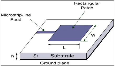
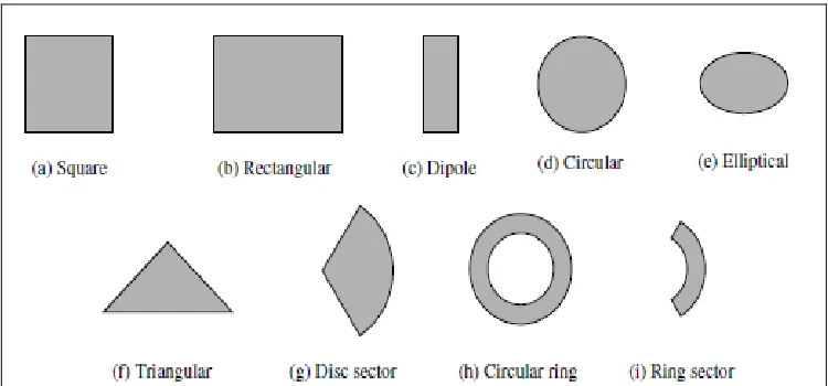
characteristics of the transmitted electromagnetic energy desired, the radiating element may be square, rectangular, triangular, or circular and is separated from the ground plane layer as shown in Figure 1.1. The metallic patch can take many different configurations, as shown in Figure 1.2, the rectangular and circular patches are the most popular
[image:22.612.207.450.538.676.2]because of ease of analysis and fabrication, as well as their attractive radiation characteristics, especially low cross-polarization radiation.
3
A microstrip patch antenna is a type of antenna that offers a low profile, i.e. thin
and easy manufacturability, which provides a great advantage over traditional antennas. Patch antennas are planar antennas used in wireless links and other microwave
[image:23.612.140.515.164.339.2]applications.
Figure 1.2: Different types of patches (Balanis, 1997).
1.3 Microstrip Antenna Advantage and Limitation:
Microstrip patch antennas have numerous advantages compared to conventional microwave antennas, and for that many applications cover the broad frequency range from 100 MHz to 100 GHz. Some of principle advantage of microstrip antenna is presented by (Garge et al., 2001).
i. Light weight, low volume, and thin profile configurations, which can be conform.
ii. Low fabrication cost, eagerly amenable to mass production. iii. Linear and circular polarizations are possible with simple feed. iv. Dual frequency and dual polarization antennas can be easily made.
v. Can be easily integrated with microwave integrated circuit.
4
And the limitation of microstrip antenna compared with conventional microwave antennas:
i. Narrow Bandwidth (BW) and associated tolerance problems. ii. Complex feed structure required for high performance arrays. iii. Unrelated radiation from feeds and junction.
iv. Excitation of surface waves.
v. Lower power handling capability (100 Watt).
1.4 Problem Statements
The main drawback of microstrip patch antenna that will be used in wireless communication is suffered from narrow bandwidth. Antenna bandwidth can be
improved by increasing the substrate height (with using transmission line model). The height of substrate increases surface waves, which pass through the substrate and scattered at bends of the radiating patch which take up apart of energy of the signal thus decreasing the desired signal amplitude caused degradation the antenna performance. To overcome this problem, the technique of air-gap is used in which surface waves is not excited easily. The resonant frequency can be tuned by compromise between two factors the height of the substrate and the length of the patch without need for new design.
1.5 Project Objectives
The main objective of this project is to design and simulate microstrip patch antenna for using IEEE 802.16 for WiMax applications using 3.5 GHz.
5
ii. To improve the bandwidth by increasing the thickness of dielectric substrate and dielectric constant with lower value. By increasing the Bandwidth more data can be carried out, on the other side high Q-factor gives better directivity hence more gain for that here a trade off is required between Bandwidth and Q-factor (quality factor). Reduce the microsrip bandwidth limitation due to the narrow band of microstrip patches in order to increase the bandwidth.
iii. To reduce the cost used in the fabrication of the antenna by using the cheap and popular FR4 material that used as a substrate material. The resonant frequency of the fabricated microstrip patch antenna can easily adjust without require additional design by just varying the height of the air-gap also as well as the FR4 material this will be made the fabrications very cost effective.
iv. To reduce the energy loss that happening from surface wave, the surface waves consume apart of energy of the signal thus decreasing the desired signal
amplitude and contributing to deterioration in the antenna efficiency that weaken the microstrip antenna’s performance.
1.6 Project Scopes
The scopes of this project have various strategies can be used for this purpose such as: i. Use the resonant frequency 3.5 GHz for WiMax application, the resonant
frequency is chosen from IEEE 802.16-2004 span of 2-11GHz.
ii. Choose the air as dielectric substrates that have the value of dielectric constant 1 in order to reduce the surface wave excisions.
iii. Utilize the transmission Line model for calculation of patch dimension. It’s simplest of all and gives good physical insight.
6
CHAPTER 2
LITERATURE REVIEW
2.1 History
Guglielmo Marconi opened the way for modern wireless communications in1895, by transmitting the three-dot Morse code for the letter ‘S’ over a distance of three
kilometers using electromagnetic waves. From this beginning, wireless communications has developed into a key element of modern society. From satellite transmission, radio and television broadcasting to the now ubiquitous mobile telephone, wireless
communications has revolutionized the way societies function (Schiller, 2000). In 1901 Guglielmo Marconi sent telegraphic signals across the Atlantic Ocean from Cornwall to St. Johan’s Newfoundland, it covers a distance of 1800 miles. His invention allowed two parties to communicate by sending each other alphanumeric characters encoded in an analog signal by (Stalling, 2004). Wireless communications is enjoying its fast growth period in history, over the last century, wireless technologies have led towards the radio, television, Paging system, Cordless phone, Mobile telephone, Satellite and wireless networks. This advancement in wireless communication is widely deployed and used throughout the world in last four decades (Rappaport, 2002). Due to Lightman & Rojas (2002) said the first practical standard of cellular communication named First
Generation (1G) was deployed and used in 1980. 1G uses the analog signal for
7
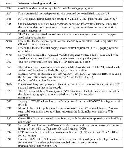
[image:28.612.127.551.208.713.2]now a day's industries are working on Fourth Generation (4G). The early1990s marked the beginning the fully of digital system, the IEEE standard looks like the winner for local area networks, it works at 2.4GHz and infrared offering 2 Mbit/s up to10 Mbit/s with special solution, (Schiller, 2000). The sequence time of wireless technology development is shown in Table 2.1 by (Dubendorf, 2003).
Table 2.1: Simple timeline in wireless technologies evolution Year Wireless technologies evolution
1896 Guglielmo Marconi develops the first wireless telegraph system
1927 First commercial radiotelephone service operated between Britain and the US 1946 First car-based mobile telephone set up in St. Louis, using ‘push-to-talk’ technology 1948 Claude Shannon publishes two benchmark papers on Information Theory, containing
the basis for data compression (source encoding) and error detection and correction (channel encoding)
1950 TD-2, the first terrestrial microwave telecommunication system, installed to support 2400 telephone circuits
1950s Late in the decade, several ‘push-to-talk’ mobile systems established in big cities for CB-radio, taxis, police, etc.
1950s Late in the decade, the first paging access control equipment (PACE) paging systems established
1960s Early in the decade, the Improved Mobile Telephone System (IMTS) developed with simultaneous transmit and receive, more channels, and greater power
1962 The first communication satellite, Telstar, launched into orbit
1964 The International Telecommunications Satellite Consortium (INTELSAT) established, and in 1965 launches the Early Bird geostationary satellite
1968 Defense Advanced Research Projects Agency – US (DARPA) selected BBN to develop the Advanced Research Projects Agency Network (ARPANET),
the father of the modern Internet
1970s Packet switching emerges as an efficient means of data communications, with the X.25 standard emerging late in the decade
1977 The Advanced Mobile Phone System (AMPS),invented by Bell Labs, first installed in the US with geographic regions divided into ‘cells’ (i.e. cellular
telephone)
1983 January 1, TCP/IP selected as the official protocol for the ARPANET, leading to rapid growth
1990 Motorola files FCC application for permission to launch 77 (revised down to 66) low earth orbit communication satellites, known as the Iridium System (element 77 is Iridium)
1992 One-millionth host connected to the Internet, with the size now approximately doubling every year
1993 Internet Protocol version 4 (IPv4) established for reliable transmission over the Internet in conjunction with the Transport Control Protocol (TCP)
1994 FCC licenses the Personal Communication Services (PCS) spectrum (1.7 to 2.3 GHz) for $7.7 billion
1998 Ericsson, IBM, Intel, Nokia, and Toshiba announce they will join to develop Bluetooth for wireless data exchange between handheld computers or cellular
8
Table 2.1 (Continued)
1999 Late in the decade, Virtual Private Networks (VPNs) based on the Layer 2 Tunneling Protocol (L2TP) and IPSEC security techniques become available
2000 802.11(b)-based networks are in popular demand
2001 Wired Equivalent Privacy (WEP) Security is broken. The search for greater security for 802.11(x)-based networks increases
2.2 Basic Communication System
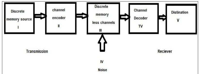
[image:29.612.120.551.95.166.2]Shows the illustrate of communication system block diagram in Figure 2.1
Figure 2.1: Block diagram of digital communication system (Haykin, 1998).
[image:29.612.122.535.263.416.2]01
2.3 The Cellular Concept
The cellular concept was a major breakthrough in solving the problem of spectral
congestion and user capacity. It offered high capacity with a limited spectrum allocation without any major technological changes. The cellular concept is a system level idea in which a single, high power transmitter (large cell) is replaced with many low power transmitters (small cells). The area serviced by a transmitter is called a cell. Each small powered transmitter, also called a base station provides coverage to only a small portion of the service area. Base stations close to one another are assigned different groups of channels so that all the available channels are assigned to a relatively small number of neighboring base stations. Neighboring base stations are assigned different groups of channels so that the interference between base stations is minimized. By symmetrically spacing base stations and their channel groups throughout a service area, the available channels are distributed throughout the geographic region and may be reused as many times as necessary, so long as the interference between co-channel stations is kept below acceptable levels (Manoj & MS, 1999). In 1968 Bell Labs proposed the cellular
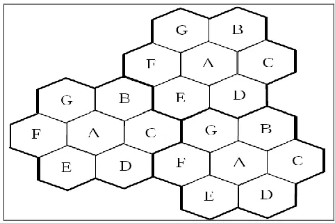
[image:30.612.206.447.520.680.2]telephone concept to the Federal Communications Commission (FCC). Then it was approved, it used the spectrum frequency of 845MHz to 870-890MHz band (Clint & Collins, 2007). In 1960 to 1970’s Bell working on mobile system give the concept of dividing the coverage area into small cells, each of reused portions of spectrum. This leads to greater system infrastructure. It is the hexagon geometry cell shape (Rappaport, 2002).
00
In Figure 2.2, the cells labeled with the same letter use the same group of channels. The frequency reuse plan is overlaid upon a map to indicate where different frequency channels are used. The hexagonal cell shape shown is conceptual and is a simplistic model of the coverage for each base station. The hexagon has been universally adopted since the hexagon permits easy and manageable analysis of a cellular system, also considering geometric shapes which cover an entire region without overlap and with equal area; hexagon has the largest area considering the distance between the center of a polygon and its farthest perimeter points. The actual footprint is determined by the contour in which a given transmitter serves the mobiles successfully (Manoj et al., 1999).
2.4 Different Mobiles Generation
Mobile telephony dates back to the 1920s, the progress was made in 1930s with the development of frequency modulation (FM). The limited mobile telephony service became available in 1940s. But systems were limited capacity. However, and it took many years for mobile telephone to become a viable commercial product (Clint & Collins, 2007).
2.4.1 First Generation System
Mobile communication as we know it today really started in the late 1970s with the implementation of trail system in Chicago in 1978. The system used a technology known as Advanced Mobile Phone Service (AMPS), operating in 800 MHz band for numerous reasons. However, including the breakup of AT&T, it took a few years before commercial system was launched in the United States. Lunching occurred in Chicago in 1983. The European also was active in mobile communications technology. The
01
operating in 450 MHz band. NMT was developed to operate in the 900 MHz band and known as Total Access Communication System (TACS) (Clint Smith & Collins, 2007).
2.4.2 Second Generation System
Unlike first generation system, which are analogue, second generation systems are digital. The use of digital technology has a number of advantages, including increased the capacity, greater security against fraud, and more advanced service, various type of second generation technology have been developed like Time Division Multiple Access (TDMA), Code Division Multiple Access(CDMA),Global System for Mobile
communications (GSM) (Clint & Collins, 2007).
2.4.2.1 GSM
Global System for Mobile Communications, or GSM (originally from Group Special Mobile), is the world's most popular standard for mobile telephone systems. The GSM Association estimates that 80% of the global mobile market uses the standard and used by over 1.5 billion people across more than 212 countries, which enable the subscribers can use their phones throughout the world, enabled by international roaming
arrangements between mobile network operators. It supports 8 time slotted users for each 200 KHz radio channels. It uses the 890-915MHz for uplink and 935-960 MHz for downlink.
2.4.2.2 Interim Standard (IS-136)
02
2.4.2.3 Personal Digital Cellular (PDC)
The Personal Digital Cellular or Pacific Digital Cellular (PDC) system is a second-generation mobile phone technology introduced in 1991. Although it is only found in Japan, its use there is very widespread and there are a considerable number of users. This technology is the move from analogue to digital technology. It uses TDMA
technology and it is very similar to the US "TDMA" or IS54 / IS136 system but operates in the 800 and 1500 MHz bands. The modulation scheme, voice frame size, TDMA frame duration, and interleaving remain the same. The major difference is that it uses a 25 KHz channel spacing instead of 30 KHz.
2.4.2.4 Interim Standard 95 (IS-95)
It relates to second generation technique which is known as Code Division Multiple Access (CDMA). It is based on Direct Sequence CDMA multiple access. Thus multiple users simultaneously share the same channel (Channel Spacing is 1.25 MHz (Rappaport,
2002).CDMA is widely used in all over the world.
2.4.3 Third generation system
03
The International Mobile Telecommunication-2000 (IMT-2000) effort within International Telecommunication Union (ITU) has led a number of recommendations. These recommendations address areas such as user bandwidth (144 kbps for mobile service and up to 2Mbps for fixed service). In 1998, numerous air interface technical proposal were submitted. These were reviewed by the ITU, which in 1999 selected five technologies for terrestrial service (non satellite based). The five technologies are:
1. Wideband CDMA (WCDMA)
2. CDMA2000 (an evolution of IS-95 CDMA)
3. TDD-CDMA (Time CDMA [TD-CDMA] and Time Division-Synchronous CDMA [TD-SCDMA])
4. UWC-136(an evolution of IS-136) 5. DECT
These technologies represent the foundation for a suit of advanced mobile multimedia communications services and are starting to be deployed across the globe (Clint & Collins, 2007).
2.4.4 Forth generation system and beyond
Forth generations will be an Internet Protocol (IP) based solution and allow seamless mobility between 3G wireless networks and fixed wireless, allowing users to take
advantage of technology access method that best suits the environment in which they are located. The prevalence of IP ensures that this type of protocol will be in existence for many years to come with no other technology access that exceeds adoption and
04
2.5 Wireless local loop (WLL)
The rapid growth of the Internet has created an equivalent demand for broadband internet and computer access from businesses and homes throughout the world. There are numerous of wireless data systems that can and do complement a mobile wireless network.
2.5.1 WiFi (802.11)
Wireless Fidelity (WiFi) is a wireless local area network based on 802.11 standards. The prevalence of WiFi is now standard feature for laptops, computers, and personal digital assistance (PDAS). WiFi enable various computers or separates local area network (LAN) to be connected together into a LAN or a wide area network (WAN). 802.11 are important for wireless mobility because it provides direct mobile data interoperability between the LAN of a corporation and the wireless operator's system.
2.5.1.1 IEEE 802.11b
The 802.11b standard was published in 1999 and has been adapted widely by
manufacture of infrastructure, such as access points, routers, and bridges. It also adapted widely by vendors of interface devices for laptops, desktops, and PDAS. 802.11b
operates in industrial, scientific and medical (ISM) band at 2.4 GHz and specify data rates of up to 11 Mbps. The standard Direct Sequence Spread Spectrum (DSS) Complimentary Code Keying (CCK) and Packet Binary Convolution Coding (PBCC) (Clint & Collins, 2007).
2.5.1.2 IEEE 802.11g
05
Orthogonal Frequency Division Multiplexing (OFDM) and also is abackward compatble with 802.11b. This mean that any 802.11g device must be able to coexist with 802.11b devices.
2.5.1.3 IEEE 802.11a
WiFi system using 802.11a specification operates in Unlicensed National Information Infrastructure (UN11) band, which enables systems using this exacting network to operate not only at higher speeds but also at higher power. The 802.11a operate the UNII band at 5GHz and uses OFDM as its modulation design. 802.11a is designed to provide data rate of up to54 Mbps. The 802.11a are not compatible with
802.11b/802.11g, its not abnormal to use them both in enterprise network. Most users may be employing 802.11b/802.11g, while power users may be assigned to 802.11a.
2.5.1.4 IEEE 802.11n
802.11n protocol is designed to poorly replace 802.11a, b, and g for local area networking. 802.11n enables speeds of 540 Mbps through improved modulations schemes and increased channel bandwidth that achieved by joining two channels therfor rising the bandwidth from 20MHz to 40MHz. 802.11n uses multiple antennas to both send and receive information, the multiple antenna system is normally referred to as Multiple Input Multiple Output (MIMO), this applications incraease the range of the 802.11n network as well as the throughput is well.
2.6 Bluetooth
06
switching time for transmission and reception is 220 micro second. Bluetooth is designed for low power consumption, with short range depending on the power class. Bluetooth can effectively operate as an extension of a LAN or a peer to peer LAN to provide connectivity between a mobile device and the other device type as printers, PDAs, mobile phones, LCD projectors, wireless LAN device, notebooks and desktops PCs (Clint & Collins, 2007).
2.7 IEEE 802.16
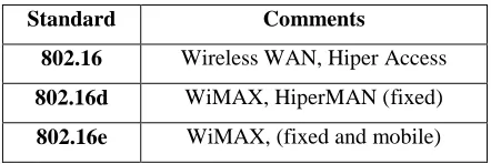
[image:37.612.217.438.453.527.2]802.16 is referred to as Wireless Metropolation Area Network (wireless MAN) and subcomponent of the standard is called Worldwide Interoperability for Microwave Access (WiMAX) and falls under 802.16 d/e, 802.16 is a set of evolving IEEE standards that are related to a huge array of spectrum ranging from 2 to 66 GHz, currently that include both licensed and un licensed bands the following table gives a brief overview of some of the various 802.16 specifications.
Table 2.2: Define some of the various 802.16 specifications.
Standard Comments
802.16 Wireless WAN, Hiper Access
802.16d WiMAX, HiperMAN (fixed)
802.16e WiMAX, (fixed and mobile)
07
broadband service implementation (Clint & Collins, 2007). The 802.16 standard has many fundamental properties
1- It supports multiple services simultaneously. 2- Bandwidth on demand.
3- Link adaption (4QAM/16 QAM /64 QAM).
[image:38.612.120.550.244.318.2]4- Point to point topology integrated with mesh topology (Clint & Myer, 2004).
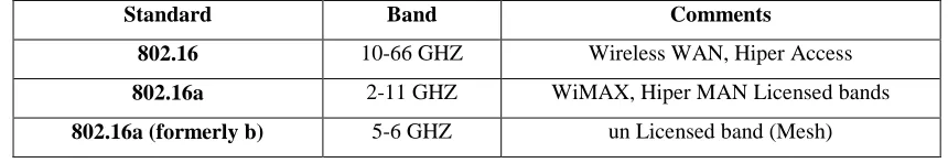
Table 2.3: The different 802.16 specification occupy inside different bands.
Standard Band Comments
802.16 10-66 GHZ Wireless WAN, Hiper Access
802.16a 2-11 GHZ WiMAX, Hiper MAN Licensed bands
802.16a (formerly b) 5-6 GHZ un Licensed band (Mesh)
2.7.1 IEEE 802.16d
The specification 802.16d is also referred to as 802.16-2004, the 802.16d focuses on spectrum that is between 2-11GHz. 802.16d use both Orthogonal Frequency Division multiple (OFDM) as well as Frequency Division multiple Access (OFDMA) techniques. Worldwide, 802.16d is meant for 3.5 and 10.5 GHz bands because they are seen as good prospects for residential and small business service.
2.7.2 IEEE 802.16e
08
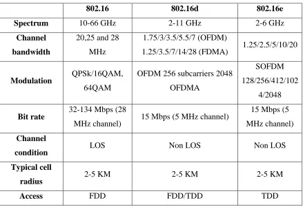
Table 2.4: Comparison of different 802.16 standards.
802.16 802.16d 802.16e
Spectrum 10-66 GHz 2-11 GHz 2-6 GHz
Channel
bandwidth
20,25 and 28 MHz
1.75/3/3.5/5.5/7 (OFDM)
1.25/3.5/7/14/28 (FDMA) 1.25/2.5/5/10/20
Modulation QPSk/16QAM,
64QAM
OFDM 256 subcarriers 2048 OFDMA
SOFDM 128/256/412/102
4/2048
Bit rate 32-134 Mbps (28
MHz channel) 15 Mbps (5 MHz channel)
15 Mbps (5 MHz channel)
Channel
condition LOS Non LOS Non LOS
Typical cell
radius 2-5 KM 2-5 KM 2-5 KM
Access FDD FDD/TDD TDD
Wi-Max technology appears to be on great economic and practical success for two reasons, first, ability to support mobile applications (802.16e) is very promising and also it can provide greater transmission range as compare to WLAN.
2.8 Importance of Antenna in Wireless System
11
2.9 Antennas Types
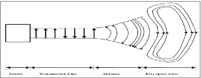
[image:40.612.166.508.217.350.2]Antennas are key components of any wireless communication system. They are the devices that allow for the transfer of a signal to waves that, in rank, propagate through space and can be received by another antenna. The receiving antenna is responsible for the reciprocal process, that of turning an electromagnetic wave into a signal or voltage at its terminals that can subsequently be processed by the receiver (Volakis, 2007).
Figure 2.3: Antenna is transition device (Balanis, 1997).
When a sinusoidal voltage source is applied across a transmission line the electric field is created between two conductors which in turn provides magnetic field due to time varying electric and magnetic fields electromagnetic waves are created and travel
through the transmission line to the antenna and radiate in free space. Some forms of the various antennas types.
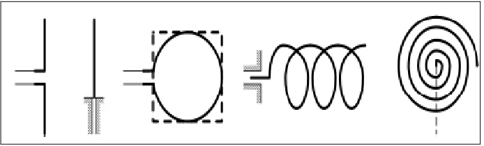
2.9.1 Wire Antennas
10
Figure 2.4: Wire antenna configurations. From left to right, dipole, monopole, circular/rectangular loops, helix, and spiral. (Balanis, 1997).
2.9.2 Aperture Antennas
[image:41.612.148.503.427.524.2]The increasing demand for more complicated forms of antenna and utilization of higher frequencies made aperture antenna is more familiar than wire antenna, some forms of aperture antennas are shown in Figure 2.5. Aperture antennas are very useful for aircraft and spacecraft applications, because they can be very suitably flush-mounted on the skin of the aircraft or spacecraft
Figure 2.5: Aperture Antenna Configurations. From left to right, pyramidal horn, conical horn, and rectangular waveguide. (Balanis, 1997).
2.9.3 Microstrip antenna
11
[image:42.612.151.492.134.277.2]However, these antennas can be mounted on the surface of high performance aircraft, spacecraft, satellite, missile, cars, and even handheld mobile telephones (Balanis, 1997).
Figure 2.6: Microstrip patch antenna. From left to right, rectangular patch, square patch (Balanis, 1997).
2.9.4 Array antenna
Many applications require radiation characteristics that may not be achievable by a single element. The total of radiating elements in an electrical and geometrical
arrangement (on array) will result in desired radiation characteristics. The arrangement of the array may be such that the radiation from the elements adds up to give a radiations maximum in particular direction or directions, minimum in others, or otherwise is
[image:42.612.111.542.561.672.2]desired. They are the different types that shown in Figure 2.7 such microstrip patch array (Balanis, 1997).
12
2.9.5 Reflector Antennas
[image:43.612.158.500.245.347.2]Because of the need to communication over great distance, sophisticated forms of antennas had to be used in order to transmit and receive signals that had to travel millions of miles. A common antenna form for such application is a parabolic reflector shown in Figure 2.8. The diameter of this antenna is as large as 305 m. Such large dimensions are needed to achieve the high gain required to transmit or receive signals after millions of miles of travel (Balanis, 1997).
Figure 2.8: Typical reflector antennas. From left to right, parabolic reflector with front feed, parabolic reflector, and corner reflector (Balanis, 1997).
2.9.6 Lens Antennas
13
Figure 2.9: Typical lens antennas (Balanis, 1997).
2.10 Antenna characteristics
It is necessary to describe the characteristics of antenna, especially concentrate on characterizing a transmit antenna.
2.10.1 The transmitting antenna
The transmitting antenna is a device that converts the energy of a guided wave into the energy of a free space wave, with the radiation power distributed in a certain pattern in space. The thevenin equivalent circuit in Figure 2.10 can be used to analyze the performance of electrically small transmitting antennas, where (Monser, 1996) Rrad is the radiation resistance, which is related to the radiated power as
= * (2.1)
REFERENCES
Antennas, (2011): Microstrip (Patch) Antennas, antenna-theory.com. Patch antennas, microstrip antennas. Retrieved, MAR 19, 2011, from URL
http://www.antenna-theory.com/antennas/patches/antenna.php#introduction.
Balanis, C. A. (1997): Antenna Theory- Analyses and Design, 2nd Edition, John Wiley and Sons, Inc., ISBN: 0-471-59268-4.
Clint, S. P. E. and Collins, D. (2007): 3 G Wireless networks. 2nd. United States of America: Mc Grow Hill Companies.
Clint, S. P. E. and Myer, J. (2004): 3G Wireless with WiMAX and WiFi: 802.16 and 802.11. United States of America: Mc Grow Hill Companies.
Cui, Y. (2006): Antenna Design for On-the-body Sensors, Technical University of Denmark.
Dubendorf, V. A. (2003): Wireless data technologies. The Atrium, Southern Gate, Chichester, West Sussex, England: John Wiley & Sons Ltd.
68
Ghosh, (2008): MICROSTRIP ANTENNAS, Retrieved, MAR 18, 2011. Retrieved, M MAR 25, 2011, fromURL
http://microstrip- antennas.blogspot.com/2008/06/basic-concepts-and-terminology.html.
Gonzalez, G. (1997): Microwave Transistor Amplifiers Analysis and Design, 2nd edition, Prentice Hall, ISBN 0-13-254335-4.
Haykin, S. (1998): Digital Communications, Johan Wiley and Sons, ISBN: 0-471- 63775-0.
IMA, E. M. (2007): FR4 Laminate, IML GROUP PLC, Retrieved, MAR 18, 2011, from URL http://www.emtworldwide.com/article.aspx?ArticleID=8609.
Kugan, (2010): Malaysia to get WiMAX on the 2.6 GHz frequencies, Malaysian Wireless, Internet Telcos and more. Retrieved, FEB 19, 2011, from URL
http://www.malaysianwireless.com/2010/02/malaysia-to-get-wimax-on-26-ghz
Lightman, A. and Rojas, W. (2002): Brave New Unwired World, John Wiley & Sons, NewYork, Inc., ISBN: 0-471-44110-4.
Manoj, K. R. et al. (1999): Coverage Estimation for Mobile Cellular Networks From Signal Strength Measurements. University Of Texas at Dallas: Ph.D. Thesis.
Monser, G. J. (1996): Antenna design: A practical design, Mc Graw-Hill, 1996, ISBN 0-07-042843-3.
68
Rappaport, T. S. (1999): Wireless Communication: Principles and Practice, 2nd edition, Prentice Hall Communication Engineering and Emerging Technologies Series, ISBN: 0-13-042232-0.
Rhodes, J. E. (1999): Antenna Handbook, U.S. Marine Corps Doctrinal Publications Status.
Schiller, J. (2000): Mobile Communications, Addison-Wesley.
Smith, M. S. (1988). Introduction to Antenna. Houndmills: Macmillan educated ltd.
Stout, S. M. (1999): Compact Dielectric-Loaded Patch Antennasfor L-Band Mobile Satellite Applications. Ottawa-Carleton institute for Electrical and Computer Engineering: Master's thesis
Stutzman, W. L. and Thiele, G. A. (1998): Antenna Theory and Design, Johan Wiley & Sons, New York
Volakis, J. L. (2007): Antenna engineering handbook. 4nd. University at Stuttgart the Ohio state university: Mc Grow Hill Companies.
Waterhouse, R. B. (2003):MICROSTRIPS PATCH ANTENNAS A Designer's Guide,
Kluar Academic Publishers.
Wikipedia, (2011): Computer Simulation Technology, Wikimedia Foundation, Inc., Retrieved, MAR 2, 2011, from URL
66
William, S. (2004): Wireless Communication and Networks, 2nd edition, ISBN: 013-196790-8.
WiMAX, (2010): What is IEEE 802.16d, WiMax.com Broadband Solutions, Inc. Retrieved, MAR 1, 2011, from URL