© 2017, IRJET | Impact Factor value: 5.181 | ISO 9001:2008 Certified Journal
| Page 1488
Mechanical characterization and finite element analysis of composite
material
Ambanna. M. Narasannavar
1, G. N. Maranholkar
2, Prajakta. S. Patil
31M. Tech, Department of Mechanical engineering, K.L.S.G.I.T, Belagavi, Karnataka, India. 2Assistant professor, Department of Mechanical engineering, K.L.S.G.I.T, Belagavi, Karnataka, India. 3Assistant professor, Department of Mechanical engineering, K.L.S.G.I.T, Belagavi, Karnataka, India.
ABSTRACT : Composite materials are materials made
from two or more constituent materials with significantly different physical or chemical properties, that when combined, produce a material with characteristics different from the individual components. Composites are made up of individual materials referred to as constituent materials. The composite material is prepared from the glass fibre and the unsaturated polymer resin also known as the general purpose resin. Then the filler material teak wood powder is used to increase the strength of the glass fibre composite. The preparation of composite is being made by hand layup technique. The prepared composite is being cut to the required dimensions as per ASTM standards. Then tensile strength and impact strength of the prepared composite is carried out. Then the modeling of the specimens carried out Fusion 3600 software and the
tensile, impact analysis is carried out using ANSYS 15 software. The experimental results and analysis results are compared and checked the percentage of error.
1. INTRODUCTION
Composite materials are materials made from two or
more constituent materials with significantly
different physical or chemical properties, that when combined, produce a material with characteristics different from the individual components. The individual components remain separate and distinct within the finished structure. The new material may be preferred for many reasons: common examples include materials which are stronger, lighter or less expensive when compared to traditional materials. Composite materials are generally used for buildings, bridges and structures such as boat hulls, swimming pool panels, race car
bodies, shower stalls, bathtubs, storage tanks,
imitation granite and cultured marble sinks and counter tops. The most advanced examples perform routinely on spacecraft and aircraft in demanding environments. Composites are made up of individual materials referred to as constituent materials. There are two main categories of constituent materials: matrix and reinforcement. At least one portion of each type is required. The matrix material surrounds and supports the reinforcement materials by maintaining their relative positions. The reinforcements impart the special mechanical and physical properties to enhance the
matrix properties. A synergism produces material properties unavailable from the individual constituent materials, while the wide variety of matrix and strengthening materials allows the designer of the product or structure to choose an optimum combination. Engineered composite materials must be formed to shape. The matrix material can be introduced to the reinforcement before or after the reinforcement material is placed into the mould cavity or onto the mould surface. The matrix material experiences a melding event, after which the part shape is essentially set. Depending upon the nature of the matrix material, this melding event can occur in various ways such as chemical polymerization or solidification from the melted state. The principal factors impacting the methodology are the natures of the chosen matrix and reinforcement materials. Another important factor is the gross quantity of material to be produced.
2. METHODOLOGY
The General purpose resin (5522 polylite epoxy) act as the matrix for the composites to bind the composite material together and transfer the component forces that may act on the part of the fibres in the composite material. Fibres offer vivid range of properties due to the their unique constituents and manufacturing process and some of the key points to be looked after while selecting fibre quality, fibre volume fraction, orientation, fibre type, length of fibre. Glass fibre is a material consisting of numerous extremely fine fibres of glass. Here in this project E- type glass fibre, filler material as teak wood powder.
Table-1: Properties of epoxy resin
Density 2.64g/cm^3
Young’s modulus 1.41Gpa
Melting
temperature 100degree-200degree
S.G of the epoxy 5522
Low viscosity -
Low volatility
© 2017, IRJET | Impact Factor value: 5.181 | ISO 9001:2008 Certified Journal
| Page 1489
Table-2: Properties of E-glass fibre
Density 2500-2590 kg/m3
Longitudinal thermal
Expansion 5.04-5.4 * 10
-6/0C
Tensile modulus 72.345 GPa
Tensile strength 3.45 GPa
Elongation 4.4%
Poisons ratio 0.22
Thermal conductivity 1.05 W/m/0C
Table-3: Properties of teak wood
Specific gravity 0.55-0.66
Modulus of rupture 97.1 MPa
Elastic modulus 1 12.28 GPa
Crushing strength 54.8 MPa
2.1 Specimen preparation:
Composite specimens are prepared by using hand lay-up method. . In our experiment general purpose resin is used as a matrix material and two types of reinforcement such as glass fibre and teak wood powder are used.
Three types of specimen composites are prepared with two different types of reinforcement and base material as resin which composite consisting of different weight percentage of glass fibre and prepared different combination of slabs /work pieces as follows
1. Combination of 60% glass fibre and 40% resin.
2. Combination of 70% glass fibre and 30% resin.
3. Combination of 80% glass fibre and 20% resin.
4. Combination of 60% glass fibre, 40% resin and filler material as teak wood powder
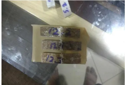
Fig-1: Prepared tensile test specimen with 70% glass fibre and 30% resin
Fig-2 : Prepared tensile test specimen with 60% glass fibre and 40% resin
Fig-3: Prepared tensile test specimen with 80% glass
© 2017, IRJET | Impact Factor value: 5.181 | ISO 9001:2008 Certified Journal
| Page 1490
[image:3.595.44.278.100.246.2]Fig-4: Prepared impact test specimen of glass fiber
Fig-5 : Prepared impact test specimen of glass fiber 3. RESULT AND DISCUSSION
3.1 Tensile strength:
[image:3.595.308.551.100.208.2]This test was according in accordance to ASTM D3039 method using a minimum of three specimens (250mm*15mm*4mm) for each composite. A Fine Spavy Associates and Engineers PVT. LTD., Miraj testing machine with software connected to a computer was used for the test. The maximum load carrying capacity of the machine is 40 tons. Tensile strength and young’s modulus are found out using the following formula ρ=F/A, E=ρL/δ.
Table -4 : Tensile strength results Material Tensile
strength (MPA)
Tensile
strength (MPA)
Tensile
strength (MPA)
Average Tensile strength (MPA) 60%GF+
40% R
126.68 97.08 104.51 109.42
70%GF+ 61.07 74.67 54.00 63.25
30%R 80%GF+ 20%R
100.23 116.43 91.74 102.8
60%G+ 40%R+ TWP
105.64 142.26 118.4 122.1
3.2 ANSYS result of the pure glass fibre composite tensile test.
Tensile test results are obtained by the ANSYS using the following data.
Tensile strength obtained from the analyses
[image:3.595.68.278.280.422.2]121.57 N/mm2.
Fig-6: ANSYS result of tensile strength for pure glass fibre
Graph -1: Tensile strength results comparison 3.3 Impact strength:
Impact test results are summarized in the following table. The addition of the reinforcement into the epoxy increases the impact strength. SL-1 pendulum impact tester machine is used to carry out the impact test. The amount of energy dissipated during the time of
0 20 40 60 80 100 120 140
60% r + 40% m
experimental result
ANSYS result
[image:3.595.317.571.318.461.2]© 2017, IRJET | Impact Factor value: 5.181 | ISO 9001:2008 Certified Journal
| Page 1491
failure is noted. As the material gets harder with increased density its impact strength decreases. Specimen was prepared according to ASTM D256 type with an angle of 450 and 2.5mm. A specimen size of
60mm*25mm*5mm was used.
Table-5: Impact strength results
3.4 ANSYS result of the pure glass fibre composite impact test.
Impact test results are obtained by the
ANSYS using the following data.
Impact strength obtained from the analyses 416.95.
Fig-7: ANSYS result of pure glass fibre impact test
3.5 Hardness:
The hardness of the given specimens were tested using barcoal hardness tester according to the
ASTM D2240.the depth of the penetration of the incident is used to characterize the hardness of the indentation in comparison to the penetration of an indenter. The values were taken at five different points and mean values are noted.
Table-6: Hardness readings
Specimen Barcoal hardness number
Pure glass fibre 35
Glass fibre with filler
material 50.33
3.6 Comparision between experimental and ANSYS results
Sl no Composite Experimental
result ANSYS results Error %
1 GF
(tensile) N/mm109.42 2
121.57
N/mm2
4.03
2 Glass fibre
(impact) 403.8 J/m 416.95 J/m 3.15
4. CONCLUSION
An experiment was conducted on universal testing machine and SL-1 pendulum impact tester machine for the prepared glass fibre composite and the glass fibre composite with filler material as teak wood powder, the experiment resulted in
1. It can be accomplished from experiment and
analysis in ANSYS 15 that the glass fiber composite with filler material as teak wood powder is having the more tensile and impact strength than the pure glass fibre composite.
2. Thus instead of using glass fibre we can replace
them with glass fibre composite with filler material of teak wood powder as it is having good mechanical properties.
3. The amount of energy absorbed during the
impact testing is more in the composite having the filler material.
REFERENCES
[1] Thomas A, Suresh P, J. Thilak J.A.F, Subramani N. Impact analysis on composite helmet by using FRC and glass fiber by using ANSYS. International Research Journal of Engineering and Technology 2017;0 4:1629-1634.
[2] Sanjay M.R, Yogesha B. Studies on mechanical
properties of jute/E-glass fiber reinforced epoxy Materials Energ
y absor bed (J) Impac t stren gth (J/m) Impac t stren gth (J/m) Impac t stren gth (J/m) Avera ge impac t stren gth (J/m) 60% GF +
40% R
3.25 403.8 576.9 624.9
2
535.2 0 60% GF+
40%R+ TWP
4.05 778.8 731.4 750.6
5
© 2017, IRJET | Impact Factor value: 5.181 | ISO 9001:2008 Certified Journal
| Page 1492
hybrid composites. Journal of Minerals and materials characterization and engineering 2016;04:15-25.
[3] Ram K, Bajpai P.K. FEM analyses of glass/epoxy
composite safety helmet. International conference on advanced material technologies 2016.
[4] Mathivanan N.R, Jerald J. Experimental investigation
of woven E-glass epoxy composite laminates subjected to low velocity impact at different energy levels 2010;09:643-652.
[5] Devendra K, Rangaswamy T. Strength