FPGA Implementation of an Agricultural Management
System using Wireless Networks
M. Aparna
MTech Student Gudlavalleru Engineering
College
Gudlavalleru, Krishna Dist, AP, India
Y.Sri Chakrapani
Associate Professor Gudlavalleru Engineering
College
Gudlavalleru, Krishna Dist, AP, India
M. Kamaraju,
Ph.D Professor and H.O.D Gudlavalleru EngineeringCollege
Gudlavalleru, Krishna Dist, AP, India
ABSTRACT
This paper presents comparison and utilization of resources, delay and minimum period with efficient data transmission using SDI of FPGA. Normally while farming, human labours must visit the fields at time to time and must check the parameters like humidity, temperature, dew point, soil moisture and water level of a well manually and regularly. This traditional method is considered time consuming and needs a lot of work and effort. In the proposed new system, the data related to different parameters will be collected and stored in flash memory. After this process, the data is analyzed, displayed in LCD screen and thedata is transmitted by SDI using different coding techniques.
Keywords
Delay, Field Programmable Gate Array (FPGA), LCD display, SDI (Serial Digital Interface).
1.
INTRODUCTION
Agriculture in India stood second in worldwide to get farm output. Agriculture plays an important role for the employment to the people. Thus to improve the quality and productivity of the green house human labour are required to visit the green house in regular intervals of time and need to check all the physical variables, which is the traditional method of farming. This is the time taken and it requires more work. To overcome the disadvantages the technology came into existence that which replaces the man with the machinery. Thus automation came into existence.
The modern agricultural management system uses the wireless networks to collect the information from different physical variables. The data which is collected by the wireless networks it is then given to the main server which in turn helps to monitor the system. For every system to be implemented cost must be low and real time monitoring are needed. Thus implementation all the agricultural systems can be done by programmable Logic devices because it allows fast development of device and the design of systems using FPGAs and CPLDs (Complex Programmable Logic Devices).
This modern agricultural management system uses FPGA element which facilitates the system for re-configurability and
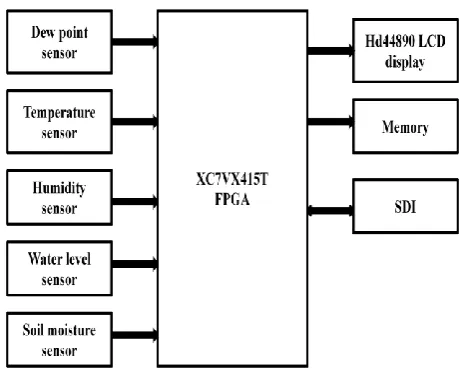
[image:1.595.313.543.287.472.2]process, the data is analyzed, displayed in LCD screen and the data is transmitted by using different coding techniques. The following figure 1 shows the system architecture.
Figure 1 System architecture of agricultural management system
The Xilinx virtex-7 series (XC7VX415T) FPGA is used for implementing the system. The SDI is a standard interface developed by SMPTE and is extensively used in specialized transmit video apparatus. The features of this FPGA are
It consists of up to 2M logic cells with 6.8 billion transistors at 12.5 GB/s serial transceivers.
With 6-input LUT technology.
It has the capability of data buffering with 36Kb RAM with built-in FIFO logic.
It consists of inbuilt XADC which is 12-bit 1MSPS ADC with thermal and supply sensors as on chip.
International Journal of Computer Applications (0975 – 8887) Volume 105 – No. 18, November 2014
The Xilinx LogicCORE IP SMPTE SD/HD/3G-SDI core implements for the SDI family of standards. They are SD/HD/3G-SDI standards.
3.
IMPLEMENTATION
In this paper, the subsequent commands of the HD44780 were used and they are listed below in Table 1.
Table: 1- FPGA Implementation instruction set.
Function
Data bits
DB0 DB1 DB2 DB3 DB4 DB5 DB6 DB7
Clear display
1 0 0 0 0 0 0 0
Function set
- - F N DL 1 0 0
Write data
D0 D1 D2 D3 D4 D5 D6 D7
Display on/off
B C D 1 0 0 0 0
Entry set S I/D 1 0 0 0 0 0
Two modes of data transfer can be done,4-bit mode and 8-bit mode. In this paper the LCD module is used in 8-bit mode. The following figure 2(A) (B) shows the flowchart of Data transfer.
(A)
(B)
Figure 2(A), (B) flow chart for sending the character and initialization
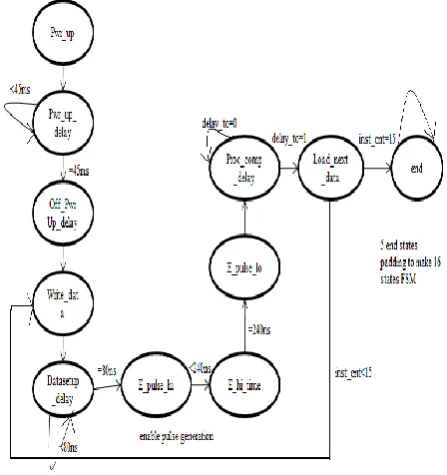
[image:2.595.333.522.67.331.2]Following this, a finite state machine is devised to ensure the process flow as above in figure 3.
Figure 3 State machine for interfacing FPGA to LCD
[image:2.595.317.541.389.627.2]Figure 4 FSM state diagram of SMPTE SD/HD/3G-SDI.
[image:3.595.319.540.375.498.2]The overall implementation of the SDI module is done using the state diagram shown in fig 4.The decode address state is the default one, it checks whether the valid channel is enable or not, and depending on the mode of operation of the SDI module the operation takes place. Every time during loading the data we must check the FIFO state, if it is full we must wait till it becomes empty and finally we must load the parity bit, at last checking for the parity error by using CRC. Finally, after checking the parity error the state changes to the default state decode address with next clock edge. The following table 2 shows the coding of the state diagram.
Table 2 coding techniques applied to the state diagram
STATE BINARY CODE
EXCESS-3 CODE
GRAY CODE
ONE-HOT
S0 0000 0000 00011 00000000000001
S1 0001 0001 00100 00000000000010
S2 0010 0011 00101 00000000000100
S3 0011 0010 00110 00000000001000
S4 0100 0110 00111 00000000010000
S5 0101 0111 01000 00000000100000
S6 0110 0101 01001 00000001000000
S8 1000 1100 01011 00000100000000
S9 1001 1101 01100 00001000000000
S10 1010 1111 01101 00010000000000
S11 1011 1110 01110 00100000000000
S12 1100 1010 01111 01000000000000
S13 1101 1011 10000 10000000000000
The states of the state machine can be coded by using different coding techniques. The binary encoding is the simplest one which is a state number binary count in sequence. While in one hot one bit is ‘high’ for any state in the state register and requires a slight logic, hence widely used in FPGA’s. Speed is the main parameter for every system or device that is designed and that is indicated by minimum period, here based on the analysis binary encoding is faster.
Even though it may be estimated that one-hot would be the fastest this would happen in the one-hot optimized technique. The gray method of encodingis similar in the performance to binary.
4.
RESULTS
International Journal of Computer Applications (0975 – 8887) Volume 105 – No. 18, November 2014
Figure 5 TOP module of FPGA to LCD interfacing
Now after checking the synthesis report, in implementation and simulation is the next step in which behavioural check syntax is done and after successful completion of this
[image:4.595.121.478.318.493.2]process,we must simulate the behavioural model thus the following simulation results are generated for LCD display as in the figure 6.
Figure 6 Simulation result of LCD display Module
Here the command given is the 01 which is used for display on/off control. Register select=0. The LCD_DB[7:0]=00001111 which indicates the LSB four 1’s as displaying, blinking and controlling.
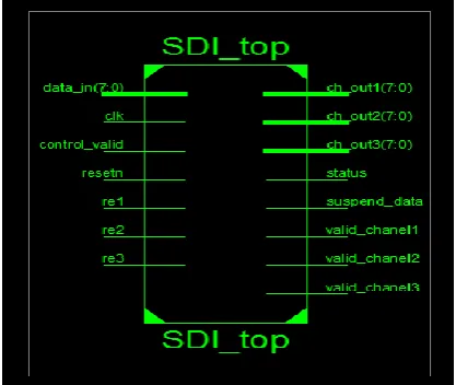
[image:4.595.194.403.562.738.2]Figure 8 simulation result of SDI module
[image:5.595.49.287.373.593.2]The above fig 8 shows the simulation result of SDI module with re1 as enable and valid channel1 as enable with data in is present at the output of the channel1. The following table 3 shows the four coding techniques utilization summary, delay and minimum period.
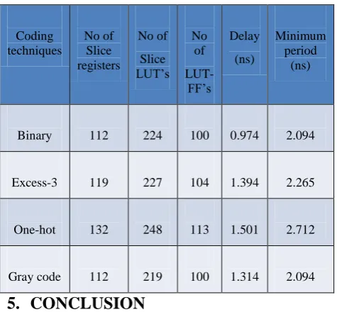
Table 3 Comparison of utilization summary for different coding techniques along with delay and minimum period
Coding techniques
No of Slice registers
No of
Slice LUT’s
No of
LUT-FF’s
Delay
(ns)
Minimum period
(ns)
Binary 112 224 100 0.974 2.094
Excess-3 119 227 104 1.394 2.265
One-hot 132 248 113 1.501 2.712
Gray code 112 219 100 1.314 2.094
5.
CONCLUSION
It is clear that the one-hot and excess-3 requires more number of utilization resources and has more delay due to more number of bits used per state. Now among other two coding techniques, gray code requires more complex hardware when compared to the binary during the state transition hence delay is more for gray code compared to binary.Thus Binary gives the best speed and with less number of utilization resources.
Thus the data is analysed, displayed using HD44890 LCD screen and the data is transmitted using SDI using different
coding techniques like Binary, Gray code,Excess-3 code and One hot encoding and the utilization of devices are shown in table of comparison along with the delay and minimum period of different coding techniques.
6.
FURUTE SCOPE
It is known that SDI which is a family of society of motion picture and television engineers (SMPTE) is widely used in professional broadcast video equipment. Thus by using the SDI module not only data can be transmitted but also video can also be transmitted.
7.
REFERENCES
[1] Y. Kim, R. Evans and W. Iversen, “Remote Sensing and Control of an Irrigation System Using a Distributed Wireless Sensor Network”, IEEE Transactions on Instrumentation and Measurement, pp. 1379–1387, July 2008.
[2] Swarup S. Mathurkar, D. S. Chaudhari, A review on smart sensors based monitoring system for agriculture, “International Journal of Innovative Technology and Exploring Engineering (IJITEE)”, vol-2 iss-4 march-2013.
[3] Izzat Din Abdul Aziz, Mohd Hilmi Hasan, Mohd Jimmy Ismail, Mazlina Mehat and Nazleeni Samiha Haroon,Remote monitoring using wireless cellular networks, “International journal of Digital Information and Wireless Communication” (IJDIWC), 2(4) 79-83.
[4] Xilinx SMPTE SD/HD/3G-SDI- IP FACTS.
[5] Overview of Xilinx 7 series FPGA.
[6] John F.Wakerly,”digital design principles and practices”, 3rd Edition.
[7] HD44780 LCD Starter Guide.