Implementation of Motion detection and Tracking based
on Mathematical Morpohology
Sheetal Balsaraf
University of MumbaiK. J. Somaiya College of Engineering
Uday Joshi
Associate Professor, University of Mumbai K. J. Somaiya College of Engineering
ABSTRACT
Security is becoming the primary concern of society. Having a security system is therefore becoming a requirement. Video surveillance plays a vital role in security systems. Consider a video stream taken by a fixed camera to monitor motion-restricted area. The system works on a real-time video,from the camera, which is accessed frame to frame. The proposed system uses mathematical morphology for implementation. The system is implemented using a generic tool for Computer Vision applications, EmguCV package in OpenCV. The system uses absolute differencing for motion detection. Each video frame goes through image filtering, for noise removal. For handling illumination changes edge feature, contour extraction is used, to avoid spurious movements appropriate threshold is selected for respective area to be surveillance. Once motion due to target object is detected, alert is generated continuously until the alert is not de-activated. After the motion is detected, the object causing motion is tracked indefinitely in live video. Even if the subject leaves the area, it’s last location is bounded and seen on the system. It’s movements are tracked and respective frames are stored on hard disk drive.
General Terms
Computer Vision, Mathematical morphology
Keywords
Motion detection and tracking , video surveillance
1.
INTRODUCTION
Security is becoming the primary concern of society due to a booming population, increasing scarcity of jobs and growing problems especially in urban cities, the number of anti-social activities, etc. Having a security system is therefore becoming a requirement. They could save the lives of loved ones and will continue to pay for themselves by preventing damage and loss of valued property.
Motion Detection & tracking is the core problem in many computer vision applications. This strong interest is driven by a wide spectrum of promising applications in many areas such as video surveillance, Human Computer Interaction, virtual reality etc. The chief applications for such detection consist of detection of unauthorized entry, detection of a moving object which triggers a camera to record subsequent events, preventing theillumination of unoccupied spaces etc. Themotion detectoris thus a linchpin of electronic security systems. The proposed system is designed as a generic application for surveillance in a human-restricted or rather motion restricted area. For a motion-restricted area, occurrence of motion is being detected and an alarm is generated and the object causing the motion is being indefinitely tracked in a real time video stream.
2.
RELATED WORK
Motion detection and tracking is a well-investigated problem in computer vision. Broadly two approaches can be identified, the region-based approach and the boundary-based approach.[1]. Few Region-based techniques which can be listed are background subtraction and optical flow. Simple frame difference of two images is used to detect motion in background subtraction. It uses a reference background image for comparison purposes. Current image (containing target object) is Current image (containing target object) is compared to reference image pixel by pixel. Places where there are differences are detected and classified as moving objects. This method is sensitive to illumination changes and small movement in the background, e.g. leaves of trees. Many techniques have been proposed to overcome this problem [2], [3], [4]. The mixture of Gaussians [2] is a promising technique to estimate illumination changes and small movement in the background. Drawback of background subtraction is long time is required for estimating the background models. As the speed of illumination changes and small movement in the background are very slow it takes time. Illumination changes also affect optical-flow method, since its approximate constraint equation basically ignores temporal illumination changes [5]. In the case of boundary-based approaches, many of them use edge-boundary-based optical flow [6], [7], level sets [8], and active contours, such as snakes [9], balloons [10], and geodesic active contours [11]. Geodesic active contours and level sets are used in [12], but these techniques are computationally too expensive for real-time applications.
3.
GENERIC MOTION DETECTION &
TRACKING
3.1
System Architecture
Motion Detection
Noise Removal
BLOB Detection
Learning
[image:2.595.98.481.78.589.2]
HDD (images tagged with motion)
Figure 1: System Architecture for Generic Motion Detection & Tracking system.
Since images will naturally differ due to factors such as varying lighting, cameraflicker, andCCDdark currents, pre-processing is useful to reduce the number offalse positivealarms. For pre-processing purpose, image filtering is done using opening operation.
The system can be used for multiple areas to be surveillance, simply by resetting the masterFrame. For each new area, depending upon the illumination, noise level, and other factors, the video frame (image) filtering process values and threshold limit depends. In image filtering, the number of iterations for which erosion and dilation are called is adjusted. For noisy images, to avoid spurious movements of tree leaves,
erosion operation is called for higher number. If small movements need to be traced then the number needs to be small. Default value of erosion iteration is kept 4. Dilation is influenced by erosion value. Default is kept to 10. The threshold value is also set depending on the specific area.For removing shadow effects and small background movements the threshold can be customized to get better results. Default threshold value is considered as 15. Frame-to-frame tracking is done and the motion detection algorithm is called repeatedly until, the process is stopped externally. Once motion due to some object is detected, alert is generated continuously until the alert is not de-activated. After the motion is detected, the object causing motion is tracked Camera
Interface
File Video
Absolute Difference
Eroding
Dilation
Smoothing
Thresholding/Binarization
Contour Detection Motion
Location Estimation
Alert Sound
indefinitely in live video. Even if the object leaves the area, it’s last location is bounded and seen on the system. It’s movements are tracked and respective frames are stored on hard disk drive. They are stored in the Motions file, which can be viewed anytime. Fig. 5 shows architecture for Generic TLD based Motion Detection the system.
3.2 System Components
3.2.1 Video Capture
Live video stream needs to be processed. Input can be taken in two ways, using a web camera or giving path for a stored video file. The system processes every frame to track the motion.
3.2.2 Motion detection
When absolute difference of the new video frame and the masterFrame is taken, either a zero value is achieved for all the pixels above threshold in current video frame, which indicates there was no motion or a non-zero value is achieved for some pixels above threshold, which indicates there was a motion. The non-zero values are the values of the pixels causing motion which will range from 0 to 255. Thus if some difference value is achieved, motion is detected. Absolute Difference function calculates absolute difference between two frames. The frames should be of same size. This frame size is 320 x 240.
3.2.3 Image Filtering
Spurious movements in the background may be mistaken for motion. Hence such noise causing elements need to be filtered. Basic morphological operations such as erosion & dilation are used for image filtering. These operations provide wide array of uses, such as removing noise, isolation of individual elements and joining disparate elements in an image, finding of intensity bumps or holes in an image.
3.2.3.1 Dilation
This operation consists of convoluting an image A with some kernel/structuring element (B), which can have any shape or size, preferably a square or circle. The structuring element B has a defined origin/ anchor point, mostly the center of the kernel. As the kernel B is scanned over the image, the maximal pixel value overlapped by B is computed and that maximal value is replaced with the image pixel in the anchor point position. As it is seen, this operation, grows bright regions within an image. [15]
3.2.3.2 Erosion
It computes a local minimum over the area of the kernel. As the kernel B is scanned over the image, the minimal pixel value overlapped by B is computed and the image pixel under the anchor point is replaced with that minimal value. [15] Due to erosion operation background shrinks and hence noise is removed. The number of iterations, for which erode operator is called depends upon how much noise exists in the video frame. But due to erosion the borders of blob/object get shrinked. Hence dilation operation needs to be applied on the output of erosion to re-size it. Dilation is maximizing operation causes bright regions within an image to “grow”. Hence the output of dilation becomes patchy.
3.2.4 BLOB Detection
In computer vision field, blob detection specifies mathematical steps aimed at detecting specific region based on some property in a digital image. A blob is made up of pixels having the specified property in common and pixels are combined together if they share common neighbourhood.
Pixels that have values greater than the threshold are the property of interest. In a video frame, if after absolute differencing and noise removal, the value a pixel is greater than the binary threshold it is eligible to form a blob. If such a pixel has an adjacent pixel also having value greater than binary threshold, both the pixels combine in the process of forming a blob.[14] All the adjacent neighbours of each such pixel are tested for eligibility and, if they satishfy,all those pixels are merged together to form a blob. There can be multiple blobs in a video frame. To avoid blobs created by spurious movements, which are considerably small in size, the size of a blob detecting motion is limited by a blob threshold. The default value for it is set to 1000 pixels. It means that if more than 1000 pixels greater than binary threshold group together, then only the blob will be detected. Blob detection consists of three main steps. Smooth Gaussian, Binary Threshold and Co ntour detection. The output of this block is fed as an input to learning block.
3.2.4.1 Smooth Gaussian
In Gaussian filtering, each pixel in the input array is convolved with a Gaussian kernel and then all of them are summed to produce the output array. Gaussian filter removes spurious movements as it doesn’t overshoot to a step function input while minimizing the rise and fall time. [14] As Gaussian filter has the minimum possible group delay. The image, obtained after dilation, is patchy at the edges. This may hinder motion detection. Hence Gaussian filter is applied to smoothen the image.
3.2.4.2 Binary Threshold
This is the simplest segmentation method. It separates out regions in an image corresponding to object of interest that need to be analyzed. Based on the variation of intensity between the object pixels and the background pixels, separation is done. To differentiate the pixels of interest from the rest, a comparison of each pixel’s intensity value is carried out with a pre-determined threshold (which can be set according to the area to be surveillanced). If the intensity value of a given pixel is greater than the pre-determined threshold then it’s intensity value is set to 255 and if it is less than pre-determined threshold then it is set to 0.
Threshold Binary
This thresholding operation can be expressed as: Dst (x,y) = 255 ; if src(x,y)
0 ; otherwise
So, if the intensity of the pixel src(x,y) is higher than threshold, then the new pixel intensity is set to a 255. Otherwise, the pixels are set to 0.
3.2.4.3 Contour Detection
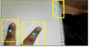
A contour is boundary of object pixels above the threshold. Contour Analysis outputs a linked list which contain blobs detected. Contours are edge-based features which are insensitive to illumination changes. Every entry of a linked list contains co-ordinates of the pixels of a respective blob. Length of linked list depends on number of blobs detected. The object is bounded using Bounding Rectangle function over the contour. Here the boundary of the blobs causing motion is identified and highlighted. If a number of blobs adjacent to each other are causing motion, and even if a single pixel becomes common amongst two adjacent blobs, the two blobs unite and common centroid is calculated to show new bounding box.
3.2.5 Learning
After contours of the blob are obtained, the location of motion is known, hence reconstruction of the image is done in color, the motion causing blob is marked, and an alert is generated. After this, the frames tracking the motion, are stored on hard disk drive. User defined interval, is kept, to store a frame, so that overloading of frames doesn’t occur.
4.
IMPLEMENTATION
4.1
Pseudo Code for Generic TLD based
Motion Detector
4.1.1 Video Capture
Step 1: If file input is true { Process the path of file
Capture the video in file }
Else
Capture the video frames from web camera Step 2: Create a backup of live image as imgMain
4.1.2 Motion Detection
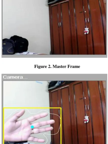
Step 1: Capture the video frame of the area to be surveillance called masterFrame
Step 2: If the image/frame taken from the video is in color, convert to grayscale
Step 3: Apply Absdiff( ) on imgGray and imgMaster resulting into imgGray
Step 4: If return value is some positive value above threshold Motion is detected
Else
No motion is detected
4.1.3 Image Filtering
Step 1: Remove noise by applying erode function for selected number of iterations
Step 2: Dilate the image to resize the shape of eroded frame After dilation, the image becomes patchy at edges. Hence to smooth the appearance Gaussian filter is applied. To identify motion, the motion causing pixels are segragated using binary threshold.
4.1.4 BLOB Detection and Learning
Step 1: Apply Smooth Gaussian to get smooth boundary .line
followed by binary thresholding
Step 2: Binary threshold the output received from step 1. (The white pixels obtained after binary threshold together form a blob, there can be more than one blobs, in an image) Step 3: Reconstruct the estimated motion area in color (BGR) Step 4: Find contours of all the detected blobs and draw on imgMain
Step 5: Reject smaller blobs by selecting appropriate threshold
Step 6: If (no. of blobs detected > 0) { Generate alert;
Store incoming frames after specified time delay; }
4.2
Processing Steps for Generic Motion
Detection & Tracking
Figure 2. Master Frame
[image:4.595.314.530.327.615.2][image:5.595.318.539.71.229.2]
Figure 5: Erosion being carried out iteratively 3 times.
Figure 6. Dilation being carried out iteratively 10 times.
[image:5.595.55.270.260.426.2]Figure 4. Output of absolute differencing
Figure 7: Applying Gaussian kernel on dilated image.
Figure 8: Applying binary threshold on Fig 7
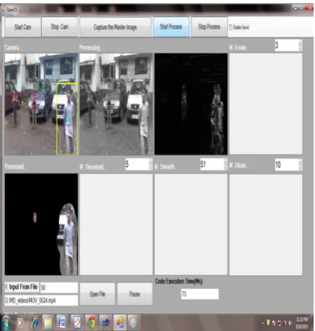
[image:5.595.315.536.262.434.2] [image:5.595.56.263.461.624.2] [image:5.595.317.544.484.723.2]Figure 10: Generic TLD motion detector taking input from a video file, showing blobs in motion
Figure 11. Generic TLD motion detector output, showing blobs in motion
5.
BUILT-IN BLOB TRACKER IN
OPENCV (VIDEO SURVEILLANCE) [13]
The OpenCV "Video Surveillance" facility, also called "blob tracker" through much of the code, is a simple but practical facility intended to track moving foreground objects against a relatively static background. Conceptually it consists of a three-stage video processing pipeline:1. A foreground/background discriminator which labels each pixel as either foreground or background.
2. A blob detector which groups adjacent "foreground" pixels into blobs, flood-fill style.
3. A blob tracker which assigns ID numbers to blobs and tracks their motion frame-to-frame.
[image:6.595.55.236.357.452.2]The foreground/background discrimination stage is both memory and CPU intensive. It builds and maintains a histogram-based statistical model of the video image background on a per-pixel basis. The implementation of video surveillance from the EmguCV package’s example folder is being considered for comparison.
Figure 11. Output of video surveillance showing multiple blobs
6.
DISCUSSIONS
6.1 Comparison of Generic Motion
Detection & Tracking system and Built-in
Blob tracker in OpenCV
Both the system were tested on a work folder consisting of 50 video streams, monitoring motion restricted areas and the Generic Motion Detection & Tracking system was compared with inbuilt video surveillance (blob tracker) and inbuilt motion detection examples.
The comparison is stated in a table.
Table 1:Comparison of Generic Motion Detection & Tracking system and Built-in Blob tracker in OpenCV
Parameter OpenCV built-in Blob
Tracker
Generic Motion Detection &
Tracking system
Algorithm Background Subtraction Frame Absolute Difference
Method IBGFG Detector is used
Pixel Differentiation &
binarization
Tracker Built-in Blob tracker
Requires no tracker. Automatically
estimates location of object-motion
Frames per
sec Low Frame rate
Almost double of built-in
Success
Ratio 50%
Threshold dependent, user
[image:6.595.315.542.384.763.2]6.2 Code Execution Time
Table 1. Table captions should be placed above the table
Algorithm Elapsed Time
(secs)
OpenCV Built-In Blob Tracker 2.0 approx
Generic Motion Detector & Tracking
1.0 approx
Code execution time for each video frame, in a video stream is experimented and average code execution time is given in above table.
7.
FUTURE SCOPE
More complex algorithms are necessary to detect motion when the camera itself is moving, or when the motion of a specific object must be detected in a field containing other movement which can be ignored. An example might be a painting surrounded by visitors in anart gallery.
8.
REFERENCES
[1] Masayuki Yokoyama, Tomaso Poggio, A Contour-Based Moving Object Detection and Tracking, Proceedings of: Visual Surveillance and Performance Evaluation of Tracking and Surveillance, 2005. 2nd Joint IEEE International Workshop.
[2] C. Stauffer and W. E. L. Grimson, “Adaptive background mixture models for real-time tracking,” in Proc. IEEE Conf. Computer Vision and Pattern Recognition, 1999. [3] Stauffer, C.; Grimson, W.E.L. , "Learning patterns of
activity using real-time tracking”, IEEE Transactions on Pattern Analysis and Machine Intelligence, vol.22, no.8, pp.747-757, Aug 2000.
[4] A. Elgammal, D. Harwood, and L. Davis, “Non-parametric model for background subtraction,” in Proc. European Conf. Computer Vision,vol. II, May 2000, pp. 751–767.
[5] J. L. Barron, D. J. Fleet, and S. S. Beauchemin, Performance of optical flow techniques,” Int’l J. Computer Vision, vol. 12(1), pp. 43–77,February 1994. [6] J. H. Duncan and T.-C. Chou, “On the detection of
motion and the computation of optical flow,” IEEE Trans. Pattern Analysis and Machine Intelligence, vol. 14, no. 3, pp. 346–352, March 1992.
[7] V. Caselles and B. Coll, “Snakes in movement,” SIAM J. Numerical Analysis, vol. 33, pp. 2445–2456, 1996. [8] J. Sethian, “Level set methods and fast marching
methods,” Cambridge Univ. Press, 1999.
[9] M. Kass, A. Witkin, and D. Terzopoulos, “Snakes: Active contour models,” Int’l J. Computer Vision, pp. 321–331, 1988.
[10]D. Cohen, “On active contour models and balloons,” CVGIP: Image Understanding, vol. 53, pp. 211–218, 1991.
[11]V. Caselles, R. Kimmel, and G. Sapiro, “Geodesic active contours,” in Proc. IEEE Int’l Conf. Computer Vision, 1995, pp. 694–699.
[12]N. Paragios and R. Deriche, “Geodesic active contours and level sets for the detection and tracking of moving objects,” IEEE Trans. Pattern Analysis and Machine Intelligence, vol. 22, no. 3, pp. 266–280, March 2000. [13]Willow Garage, Video Surveillance [Online]. Available:
http://opencv.willowgarage.com/wiki/VideoSurveillance. [14]Mathematical Morphology, Thresholding, Gaussian Filter, Blob Detection [Online]. Available: http://en.wikipedia.org
[15]OpenCV 2.4.2 Documentation [online]. Available: http://opencv.org/documentation.html