978-1-5386-1953-7/17/$31.00 ©2017 IEEE
Combining Fault Location Estimates for a
Multi-Tapped Distribution Line
H. K. Jahangera b, M. Sumnera, D.W.P Thomasa Department of Electrical and Electronic Engineering a University of Nottingham, b University of Technology-Iraq
Nottingham, UK
Abstract—Multi-tapped lines are common in integrated power systems and microgrids which supply variable loads
between the main source and the main load. Adopting a cost
effective and efficient method for fault location is important for fast power recovery and improving system reliability. A method requiring measurements only at the ends of the main distribution line is proposed in this paper to solve the issue of locating faults on the tapped lines as well as on the main line without any measurement required from the taps. A combination of single-ended and double-single-ended algorithms based on higher frequency impedance estimation are utilized to locate the faults within the tapped line. The study considers different fault types in different locations as well as various fault inception angles. The presented results shows the efficiency and the accuracy of the suggested technique with maximum error less than 3% of the total line length.
Index Terms— Fault location, impedance estimation, integrated power systems, protection and tapped lines.
I. INTRODUCTION
Fast and precise fault location algorithm on multi-tapped distribution lines of integrated power system (IPS) is very important for reducing the time required to restore the power delivered to the loads as well as to improve the reliability of the system [1]. Moreover, designing a cost effective fault location method for multi-tapped lines with the minimum number of measurements is one of the challenging issues.
Impedance based fault location methods are one of the most common methods for fault location in distribution systems. Traditional methods are based on measuring the impedance to the fault location using the fundamental frequencies (50 or 60 Hz) [2]. However, this provides an accuracy of a few hundred of meter for typical cable parameters, and hence it is not suitable for short distribution lines. The impedance based fault location methods used in this paper can be classified as one of two types, a single-ended method, which utilize the measurement from one end of the
line, and a double-ended method, which use the measurements from both terminations of the primary line [3].
Many works have been published on using impedance estimation for fault location [3]–[10]. Some of these works used only single-end measurement [3]-[7] and many other techniques used measurements from two terminals or more. A three phase voltage and current in single-ended method is used to estimate fault distance in multi-tapped distribution system while a healthy phased current at the possible faulted sections is used to discriminate between the possible locations [4-5]. While in [6] a combined single-ended impedance estimation and voltage sag matching algorithm are used to locate fault in multi-tapped system. A matching algorithm is used to compare the measured voltage sag with a data bank to decide on the faulted line [6]. In [7], a single-ended method that applicable for an unbalance and multi-source distribution network is proposed. However, In case of faults that fall on two identical laterals, the scheme is not capable of decide which the faulted lateral [7]. The method proposed in [8] require a synchronized measurement from two ends. Moreover, a load flow is required to estimate the voltages and current at the faulted section in order to estimate the exact fault distance. Three phase currents and voltages from all terminals were measured and synchronized in [9]. The authors suggested a technique which reduces the multi-terminal line to a two terminal line based on the voltage differential between the terminals [9]. Another reduction method that convert multi-terminal to two terminal method is suggested in [10]. However, the proposed algorithm is complicated. A communication system is required in the sectionalized microgrid where a central protection unit and phase measurement unit (PMU) for each section is required [11].
This section introduces the single-ended and double-ended impedance based fault location methods based at non-fundamental frequency content.
A. Single-Ended Algorithm review
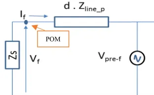
[image:2.612.50.300.333.411.2]The impedance estimation fault location method in an IPS based on a single-ended measurement will be introduced and demonstrated. A single phase circuit with a short circuit fault on the distribution line, as in Figure 1, will be used to introduce the basis of this method. The supply impedance is represented by Zs, while ZL is the equivalent load impedance. The cable impedance between the fault and the sending end is Zx and the remaining impedance Zl-x represents the cable impedance from the fault to the receiving end of the line [12].
Fig. 1 Single phase circuit with a phase to ground fault
The fault can be considered to be a voltage source which creates voltage and current transients that contains information over a wide frequency range when the fault occurs. The supply source at the non-fundamental frequencies is short circuited as shown in the Thevenin’s equivalent circuit of Figure 2, while the fault is represented as a transient source which creates an equal and opposite voltage to the instantaneous pre-fault voltage (Vpre-f) at the fault location [12].
Fig. 2 System at non-fundamental frequency during fault situation
Applying Kirchhoff’s voltage law to the non-fundamental equivalent circuit in Figure 2 in order to calculate the voltage drop from the measuring point (POM) to the fault location as in (1):
. _ = 0 (1)
is not influenced by the fault resistance and because at higher frequencies the reactance dominates the overall impedance more than the resistance.
= (3)
The Vpre-f in (2) is a created step voltage with value equal to the measured pre-fault voltage at the POM, assuming that the voltage drop between the POM and the fault location is negligible. Based on this assumption, an initial error in the fault distance estimation is presented. To estimate the correct Vpre-f, the initial estimated distance form (3) is used to calculate new Vpre-f shown in (4):
= . . (4)
An initial fault distance is estimated using (3) and this estimated distance is used to calculate new at fault location using (4). The fault location is then re-estimated using (3) and the updated calculation of . This iteration is repeated until the two successive fault location estimates converge to within an acceptable tolerance of each other, for
example, 0.5 .
B. Double-ended Algorithm review
The impedance estimation fault location method based on double ended measurements will be introduced and demonstrated using the same circuit and fault condition used to describe the single ended method. Figure 3 shows the circuit at non-fundamental frequencies using the double ended measurements, where the supply source is short circuited and the fault represented as a transient voltage source [3].
The fault provides a transient voltage, Vf, at non fundamental frequencies and Rf is the fault resistance. POM1 is the point-of-measurement at the source end, while POM2 is the point-of-measurement at the load end. Kirchhoff’s Laws are applied to the measured voltage and current during a fault for measurements at both ends of the line to calculate the impedance between POM1 and the fault. Kirchhoff’s voltage law was applied to Figure 3 to derive (5).
. . = . . (5)
[image:2.612.97.253.530.627.2]S
Fig. 3 System at non-fundamental frequency during fault situation using double-ends measurement
Where Vs, Is are the voltage and current measurements at the source end of the line and Vr, Ir are the measured voltage and current at the receiving end. The total line impedance is =
, hence:
= . (6)
The impedance between the fault point and source end is estimated using (6). The fault location can be found by dividing the estimated impedance by the per-unit length impedance of the line. As is clear from (6), the fault resistance information is not required by the double-ended method and neither are knowledge of the load and the supply impedances.
C. Tapped lines
[image:3.612.323.557.75.168.2]The system in Figure 1 is modified to contain a single tap line as shown in Figure 4 and a short circuit fault is applied on the tapped line.
Fig. 4 Single phase circuit with a fault on Tapped line
The equivalent circuit at non-fundamental frequencies will be updated to include the tap line as shown in Figure 5, (5) is also updated as follows to give (7):
. . = . . (7) Rearranging (7) in order to calculate the value of Zx produces (8):
[image:3.612.288.560.385.716.2]= . (8)
Fig. 5 System at non-fundamental frequency during fault on Tapped line using double-ends measurement
According to (8), the double-ended technique does not require details of the tapped line and its load. Hence, the tapped line may be considered as a fault impedance according to the double-ended method and the estimated distance to the fault is the distance from the supply end to tapping point P in Figure 5. As a result, the double ended technique is unable to locate faults on the tapped line, however, it has the ability to locate the faulted tapped line so it is utilised to discriminate between possible fault locations calculated using the single-ended technique.
The flowchart of Figure 6 shows the procedure used when estimating the distance between the sending end measuring point and the fault location and describes how to discriminate between the possible locations.
Fig. 6 Flowchart of the proposed process
P R
ZLoad-T
ZLoad
T Fault
[image:3.612.57.287.461.545.2]Fig. 7 Simulated IPS
The required data was measured from the sending and receiving ends of the main line of the system shown in Figure 7. Different fault types and locations were applied to the system to validate the proposed method for locating faults on tapped lines as well as the main line using only two sets of measurements.
[image:4.612.321.550.169.684.2]
Table I The IPS parameters
Circuit parameter Value
Source voltage (ph-ph) 440 (V) Source impedance 0.0011 + 0.0096i Line per-meter resistance 30 µΩ Line per-meter inductance 0.24 µH
R-end load 100 kW
Tap-end loads 20 – 30 kW Sampling frequency 100 kHz
A single line to ground (SLG) fault was initiated 30m away from POM1 on tapped line 1, tapped line 2 and then on the main line to verify the suggested procedure. In Figure 8a the fault was on Tap 1 and the single ended method estimated a fault 31.3m away, but with this distance there are three possible fault locations: on Tap 1, Tap 2 and the main line. Hence, the double ended method was used to discriminate between the possible locations: the estimated fault location was 10m from the supply using the double-ended method, which corresponds with tapping location 1. As a result of combining both methods, the fault is found to be on tapped line 1, which is the correct choice. The same process (Figures 8b and 8c) shows the estimated fault distance and how it is been discriminated from the other possible location using the double-ended method. The calculated distance is 31.3 m, while the actual distance is 30 m, which gives an error of 2.6%.
The same process is repeated with a double-line (DL) fault and double-line to ground (DLG) fault which further shows the capability combining the two methods to locate different faults types on the tapped lines without any measurement from the taps. Figure 9 presents the estimation results obtained when the
required for the error to coverage to preset tolerance.
(a)
(b)
(c)
[image:4.612.50.302.381.469.2](a)
(b)
[image:5.612.60.282.51.623.2](c)
Fig. 9 DL fault 30m away from POM1 (a) On Tapped line 1 (b) On Tapped line 2 and (c) On the main line
[image:5.612.320.554.61.525.2]Further simulations were performed using different fault locations in order to investigate the accuracy and the reliability of the presented method. The percentage error calculation are summarized in Table II and Table III for SLG and DL faults in the possible fault locations
Fig. 10 DLG fault on Tap1, Tap2 and Main Line
Table II Percent error calculation for SLG faults Actual distance (m) Estimated
distance (m)
Percentage error 00 ( on Main line) 0.128 0.25 10 ( on Main line) 10.175 0.35 20 ( on Main line) 20.18 0.35 30 ( on Main line) 30.26 0.52 40 ( on Main line) 40.35 0.7 50 ( on Main line) 50.45 1.4 30 ( Tap line 1) 30.68 1.36 30 ( Tap line 2) 30.44 0.9
50 ( Tap line 3) 50.6 1.2
Table III Percent error calculation for DL faults Actual fault distance
(m)
Estimated distance (m)
Percent error 00 ( on Main line) 0.21 0.42 10 ( on Main line) 10.10 0.20 20 ( on Main line) 20.10 0.20 30 ( on Main line) 30.124 0.25 40 ( on Main line) 40.125 0.25 50 ( on Main line) 50.142 0.285
30 ( Tap line 1) 30.50 1.00 30 ( Tap line 2) 30.275 0.55 50 ( Tap line 3) 50.225 0.45
The percentage error was calculated according to (9) given below:
= . .× 100% (9)
[image:5.612.326.544.72.231.2]Table IV influence of fault inception angle on the single-ended method. Inception angle
(degree)
% error
30 1.2 60 0.9 90 0.9 120 0.92 145 0.3 165 0.81 175 2.7 178 4.7 180 5.5
The results presented in Table IV indicates that the single-ended method can estimate the fault distance with percentage error up to 3% except when the fault is initiated near to the zero crossing point, where the error is increased to 5.5%. However, this amount of error is still within an acceptable tolerance and faults near to the zero crossing point also present a problem for other fault location methods.
IV. CONCLUSION
A combination scheme of single-ended and double-ended techniques based on impedance estimation at non-fundamental frequencies has been used for fault location in a multi-tapped integrated power system environment. The single-ended method was used to estimate the distance between the sending end (POM1) and the fault location based on the estimated reactance, while the double-ended method was used to discriminate between the possible fault locations. The presented results show that the scheme is able to locate different fault type in different fault locations with maximum error less than 3%. The method only requires measurements from the two ends of the main line in addition to knowledge of the per meter line impedance. Moreover, the method can locate the faults with high accuracy with any inception angle except when the fault is initiated near the zero crossing angle, where the error increased to 5.5%. However, this is still acceptable tolerance for fault at the zero crossing point. Future work is planned in order to validate the simulation results presented in this paper.
REFERENCES
[1] A. Emadi, M. Ehsani and J.M. Miller, Vehicular electric power systems. Boca Raton, FL: CRC, 2005, pp.15-35.
[2] T. Tagaki, Y. Yamakoshi, M. Yamaura, R. Kondow and T. Matsushima, “Development of new type fault locator using the one terminal voltage and current data,” IEEE Transactions on PowerApparatus and Systems, vol. PAS-101, no. 8, pp. 2892-2898, 1982,.
[3] K. Jia, D. Thomas and M. Sumner, “A new double-ended fault-location scheme for utilization in an integrated power system, ’’ IEEE Trans. Power Delivery, vol. 28, no. 2, pp. 594-603, April. 2013.
[4] R. Krishnathevar and E.E. Ngu, “Generalized impedance-based fault location for distribution systems,” IEEE Transactions on Power Delivery, VOL. 27, NO. 1, pp. 449-451, JANUARY 2012.
[5] R. Krishnathevar and E. E. Ngu, “A new impedance-based fault location method for radial distribution systems,” IEEE PES General Meeting, Minneapolis, pp. 1-9, 25-29 July 2010.
[6] M. Daisy and R. Dashti, “Single phase fault location in power distribution network using combination of impedance based method and voltage sage matching algorithm,” 2015 20th Iranian Electrical Power Distribution Conference (EPDC2015).
[7] Y. Liao, “A novel method for locating faults on distribution systems,” Electric Power Systems Research, pp. 21–26, 2014.
[8] J. Ramírez-Ramírez, J. Mora-Florez ; C. Grajales-Espinal, “Fault Location Method Based on Two End Measurements at the Power Distribution System,” 2015IEEE 6th Latin American Symposium on Circuits & Systems (LASCAS), Montevideo, pp. 1-4.
[9] A. Esmaeilian, M. Mohseninezhad, M. Doostizadeh and M. Khanabadi, “A precise PMU based fault location method for multi terminal transmission line using voltage and current measurement,” in Proc. 2011 10th International Conference on Environment and Electrical Engineering (EEEIC2011), pp. 1-4, 8-11.
[10] C.W Liu, K.P. Lien, C.S. Chen and J.A. Jiang,” A universal fault location technique for n-terminal ( N>=3) transmission lines,” IEEE Trans. Power Delivery, vol. 23, no. 3, pp. 1366-1373, July 2008.
[11] S. Mirsaeidi, D. M. Said, M. W. Mustafa, M. H. Habibuddin and K. Ghaffari, “Fault location and isolation in micro-grids using a digital central protection unit,” Renewable and Sustainable Energy Reviews, Vol. 56, pp. 1–17, 2016.