Achievable Rate Analysis for Full-Duplex Relay
Networks with Spatial Modulation
Subathra. T1, Prabhavathi. T2
1, 2
ECE-MVIT, Pondicherry University,
Abstract: The objective of a wireless research is to conceive a full duplex operation by aiding concurrency in both transmission and reception in a single time/frequency channel and thus enhancing the spectral efficiency than the conventional half duplex systems. Investigation is performed on the performance of a full-duplex (FD) relaying network with a single-RF Spatial Modulation (SM) Multiple-Input Multiple-Output (MIMO) system. The SM MIMO is employed at the relay node. This protocol is referred to as SM-aided FD relaying (SM-FDR). The demodulator at the destination takes advantage of the direct connectivity between the source and destination which in-turn maximizes the performance. The mathematical expressions for computing the achievable rate of SM-FDR in the presence of residual Self-Interference (SI) has been studied based on the demodulator. With the guide of these achievable rate articulations, a gauge on the nature of SI cancelation required for the appropriateness of FD transmission has been given. The scientific investigation is substantiated with the guide of MATLAB. At last, we likewise survey the execution of SM-FDR against conventional FD transferring conventions.
Keywords: Relaying, Full-duplex, Spatial modulation, MIMO, Achievable Rate Analysis.
I. INTRODUCTION
FD transmission allows the relays to transmit and receive simultaneously on the same channel, and thereby doubling the spectral efficiency effectively. However, the success of FD operation is dependent on its capability to suppress the Self-Interference (SI), i.e., the interference introduced from the relay’s transmitter to its receiver. In [1], The most popular relaying protocols available are amplify-and-forward (AF) and decode-and-forward (DF) relaying . In spite of their many advantages, one of the fundamental challenges of these relaying protocols is their requirement for extra bandwidth resources due to the half-duplex (HD) constraint of the relay, i.e., the relay cannot transmit and receive on the same frequency at the same time. This might result in a loss of system throughput.
In [2], The SI cancellation methods can be broadly classified into two categories: i) passive cancellation, which is realized by imposing path-loss between transmit and receive antennas of the relay; and ii) active cancellation, which includes analog cancellation techniques, digital cancellation techniques, or a combination of both. In [3], Rodrguez et.al studied the error rate performance of AF-based full duplex relaying in the presence of residual SI. In [4], Michalopoulos et al studied the error rate performance of DF-based full duplex relaying in the presence of residual SI. In [5], Krikidis et.al applied efficient cooperative protocols in an attempt to extract the full benefits of FD relaying. In [6], Krikidis and Suraweera proposed a distributed FD Alamouti scheme that provides significant diversity gains as the strength of the SI decreases. The hybrid relaying schemes that switch opportunistically between FD and HD relaying modes based on a pre-defined criterion was proposed and also transmit power adaptation for maximizing the spectral efficiency was applied in [7]. In [8], several relay selection policies in order to improve the outage probability of FD relaying were investigated. In [9], a distributed SM protocol, which increases the aggregate network throughput by allowing the relays to forward the data of the source while transmitting their own data, has been proposed. In [10], a cooperative space time shift keying protocol has been proposed, where the relay nodes re-encode the received data from the source onto a dispersion vector and onto a modulated symbol.
Fig.1 System model of SM-FDR protocol
Relaying system is considered, where the multi-antenna source uses transmit beam forming to forward its data to the relay, and the relay uses SM to forward the data to the destination. However, the effects of SI and the direct link have not been taken into consideration.
II. SYSTEMMODEL
A relaying dual-hop, three-node network topology is considered as shown in Fig.1. Here an Half duplex capable source, S, communicates with its intended HD destination, D, with the aid of an FD relay node, R. The assumption is that the source and the destination are provided with one antenna each, whereas the relay is equipped with NR antennas. Since there are more no. of
antennas in a single relaying node with FD capability there is always an associated Self Interference (SI), which has to be suppressed with the aid of some SI cancellation technique. However, due to practical constraints the SI cancellation to the fullest extends becomes a hard task. Therefore, it is mandatory to take into consideration the quality of the cancellation technique, and has to be accounted in any work. A direct link is also considered to exist in the model between the source and the destination. The demodulator at the destination utilizes this direct link to minimize the error-probability and to enhance the achievable rate.
In the SM-FDR, the source broadcasts its data symbol without and spatial modulation to the relay and the destination. The relay demodulates the data and then forwards it to the destination by using Spatial Modulation with the help of Multiple antennas. Meanwhile the source broadcasts a new symbol to the relay and the destination. The SM encoding process uses only one of the RF chains and hence the power consumption at the relay is considerably reduced which is an added advantage in the SM implementation. More specifically, in Sm only one of the NR antennas is chosen for activation and the estimated data of the source
at the relay is transmitted. During this activation instance, the remaining NR -1 antennas at the relay are available for reception of the
next symbol from the source. The SM implementation at the relay requires two main considerations,
1) Unlike customary point-to-point SM, the dormant antenna(s) at the hand-off in SM-FDR are not turned off. Rather they are exchanged on in the get mode. Since the images transmitted from the source are equiprobable, the dynamic/idle antenna(s) in the present schedule vacancy and in whenever opening might be unique.
2) For high information rate transmission, the RF receiving wire exchanging at the transfer to empower the concurrent transmission and the gathering of information ought to be in concurrence with image time exchanging component that is specific to SM. Luckily, fast RF switches that fill this need with low inclusion misfortune and great detachment properties have been accounted for.
III. CHANNELMODEL
The channel considered is assumed to be of Quasi-static fading. That is the wireless fading channels is assumed to remain static over one cooperative phase, i.e., two time-slots. The channel fading changes independently from one cooperative phase to another. The SI channel from the pth transmit antenna of the relay to its rth receive antenna, for r, p ∈ {1,2,…..,NR}, with p ≠ r is denoted as hRpRr
,where hRpRr = ℎ ( ) with ℎ being the fading envelope and being the channel phase. If NR =2, the SI
fading envelopes are assumed to be independent and follow Rician distribution. The mean and the variance (per dimension) of the SI channels are formulated as follows:
where: is the Rice factor; = (1 2⁄ )( ⁄ ) with being the relay’s average transmit energy per symbol, and λ being
a small positive constant which captures the quality of SI cancellation.
For instance, if λ = 0 implies a poor SI cancellation process, and λ = 1 refers to a high-quality SI cancellation process. This
modeling of SI channels as Rician are from [19]. The value NR > 2 depicts that the SI fading envelopes are assumed to be Rayleigh
distributed, i.e., the mean = 0, and their channel phases are assumed to be uniformly distributed in the interval [0,2 ].
The term “useful channels” are coined to the source-to-relay, source-to-destination and the relay-to-destination channels. The channel coefficients are denoted as ℎ , ℎ and ℎ . For the purpose of mathematical simplicity, these fading channels are assumed to be independent and follow a Rayleigh distribution with zero mean and a variance of , and , respectively.
A. Relaying Protocol
In a tth time-slot, the source broadcasts its data to the relay and the destination. The signal is received at the antennas which are inactive at the relay during the tth slot. Let and are either Phase Shift Keying (PSK) or Quadrature Amplitude Modulation (QAM) constellations, whose symbols have a power constraint of unity. The model is given for a M-ary complex modulated symbol transmitted by the source during the t-th time-slot (t) ∈ ( and the N-ary complex modulated symbol transmitted from the active antenna of the relay (t) ∈ . The received signal is given as follows:
( ) = ℎ (t) + ℎ (t) + n (t)
( ) = ℎ (t) + ℎ (t) + n (t) (2)
where, p is the index of the active antenna at relay during the t-th time-slot; and are the sources and relay’s average transmit energy per symbol, respectively. (t) is the complex Additive White Gaussian Noise (AWGN) at the input of node X during the tth time-slot. The AWGN is independent and identically distributed (i.i.d) with zero mean and variance /2 per dimension. At t = 0, i.e., during the very first instance of transmission (0) = 0 and none of the antennas at the relay are in the active mode. Hence all the NR antennas are available for reception of data. This is in contrast to the rest of the time-slots where only NR-1 antennas are
available. Therefore, at t = 0, (2) can be rewritten as follows (r = 1,2,…..,NR):
(0) = ℎ (0) + n (0)
(0) = ℎ (0) + n (0) (3)
The destination keeps the received signal (t) in (2) for further processing during the (t + 1)th time-slot. The relay, on the other hand, demodulates the received signal using the Maximum-Likelihood (ML) criterion [20]. Accordingly, the demodulator at the relay can be formulated as follows:
( ) = ( )( )∈ ( )=∑
( )
− ℎ ( )( )
( )
( ) =ẞ ( )( )
(4)
where: ( )( ) and ( )( ) are the estimated symbol and the estimated bits at the relay during the tth time-slot. ( )( ) S (t) is the trial symbol used in the hypothesis detection problem and ẞ(. ) is the symbol-to-bits mapping function at the source. This mapping function facilitates the SM encoding at the relay. During the (t+1)th time-slot, the destination can be formulated as follows:
( + 1) = ℎ (t + 1) + ℎ (t + 1)
+n (t + 1)
( + 1) = ℎ (t + 1) + ℎ (t + 1) + n (t + 1)
(5) ⎩
⎪ ⎪ ⎨ ⎪ ⎪
⎧ ( )( ) = ( )( )
∈
( )( )
∈
{ ( )( ( )
( ), ( )( + 1)}
( )( ( )
( ), ( )( + 1) = ( )− ℎ ( )( ) + ℎ ( )( )
+ ( + 1)− ℎ ( )( + 1) + ℎ ( )( + 1)
The active antenna index pʹ and the transmitted symbol (t + 1) of the relay during the (t + 1) time-slot are determined by its
estimated bits ( )( ) during the time-slot t.
B. Demodulation At The Destination
The destination receives two copies of each source’s data symbol are received. One from the source directly during time slot t and another from relay at the time slot (t+1). The destination makes use of both of these copies for potential diversity or achievable rate benefits. By applying the ML criterion, the destination, during the (t + 1) time-slot, demodulates the source’s data transmitted by it
during the t time-slot. Accordingly, the demodulator can be formulated as in (6)
where ( , ( )( ) = ℳ ẞ ( )( −1) and ( , ( )( + 1)) = ℳ ẞ ( )( )
The source’s data transmitted during the (t+1) time slot, i.e., ( + 1), is not estimated during the (t+1), although we are searching
for it over all the constellation using the trial symbol ( )( ). Actually, the estimation of x_s (t+1) is performed at the goal amid the vacancy at t+2. The ML demodulator isn't strong to conceivable demodulation blunders at the transfer. Such a demodulator, in any case, is restrictively intricate for higher-arrange regulation, and requires the learning of source-to-hand-off CSI at the receiver.
C. Instantaneous Achievable Rate Analysis
In SM-FDR, the relay first demodulates the source’s data before forwarding it to the destination using SM (it is a decode-and-forward scheme), the achievable rate of SM-FDR can be formulated as follows:
= ( , ) min { ( ; ⁄ ), ( , ; )} (7)
where X1 is the source message, X2 is the relay message, Y2 is the received symbol at the relay, and Y3 is the received symbol at the
destination. The value of this expression depends on the degree of correlation between the source message X1 and the relay message
X2. Assuming independence of X1 and X22, this reduces to:
= ( ) , ( ) (8)
where ( ) =I(X1; Y2) is the achievable rate of the links from source to relay (The source is
assumed to transmit i.i.d.
Gaussian-distributed symbols), and the effects of the SI is modeled as an additive white Gaussian noise. The parameter Y2 is a
vector of length NR -1. Using Shannon’s theorem, the achievable instantaneous achievable rate of the source to relay links can be
obtained as follows
( )
= log 1 +∑ { = } ×∑ | |
(9)
where Pr {p = Active} = 1/NR represents the probability that pth antenna is active at the relay.
_
( )
= I(X1, X2; Y3) is the mutual information between the simultaneous transmissions from source and relay and the destination
received symbol. This mutual information is evaluated from [23] assuming that the relay also transmits i.i.d. Gaussian-distributed symbols, the first term is given by:
( , ( ); | ( )= ∑ log 1 + ℎ + |ℎ |
(10) The second term is given by:
( ; ) = log χ( ℳ) (h ) (11)
The equation (11) Represents the achievable rate taking into the spatial constellation diagram in an SM transmission, with the
channel coefficient hRD emphasizing that ( ℳ)
is a function of relay-to-destination channels. The capacity can be given by,
( )
= ∑ log 1 + ℎ + |ℎ | + log χ( ℳ) (h ) (12)
SM-FDR can be computed. The ergodic achievable rate of SM-FDR can be obtained by taking the expectation with respect to channel fading in (8). For the sake of comparison, the achievable rate of the SM-HDR protocol is also given below. In SM-HDR, the transmission protocol consists of two non-overlapping timeslots. During the first time-slot, the source broadcasts its data to the destination and the relay, where all the NR antennas are in the receive mode. During the next time-slot, the relay applies SM to
forward the data it received during the previous time-slot. It is worth emphasizing that, in SM-HDR, owing to its HD operation, there is no SI distorting the reception at the relay.
Accordingly, the instantaneous achievable rate of SM-HDR can be formulated as follows:
= ( ) , ( ) (13)
Where ( ) = log 1 +∑ ( ⁄ ) |ℎ | , and ( ) = ( ) and is given by (12). The comparisons are done between FD and HD scenarios which are discussed in the next section.
IV. SIMULATION RESULTS
In this section, numerical results for the average bit error rate and achievable rate of SM-FDR and SM-HDR are shown.
Fig .2 Average bit error rate of direct, AF, DF Spatial modulated relay
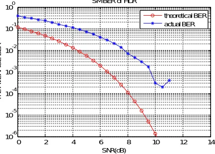
[image:5.612.95.499.241.392.2] [image:5.612.194.413.565.722.2]Fig.2 shows average bit error rate of direct, AF, DF Spatial modulated relay. The result shows that spatial modulated decode and forward protocol performs better when compared to amplify and forward and direct transmission between the source and the relay in terms of average bit error rate. At low SNR the average bit error rate is also low for DF spatial modulated relay. Fig.3 shows the bit error rate of SM-HDR using DF protocol. Fig. 4 shows the bit error rate of SM-FDR using DF protocol. By comparing Fig. 3 and Fig. 4, the result clearly shows that spatial modulated full duplex relay using decode and forward protocol produces low bit error rate at low SNR values than spatial modulated half duplex relay using decode and forward protocol.
Fig.5 shows the achievable rate of the DF based SM-FDR. The result clearly shows that achievable rate increases with increasing λ. Fig.6 shows the achievable rate of the DF based SM-HDR. In general, the results show that SM-HDR achieves a higher achievable rate compared to SM-FDR for smaller values of λ. More specifically, in the high-SNR regime, SM-HDR is better than SM-FDR for
λ < 0.5 if NR = 2, and for λ < 0.3 if NR = 4. These trends confirm the need of the analytical development, where mathematical
expressions for computing the range of λ for which SM-FDR is suitable over SM-HDR has been provided.
Fig .3 Bit error rate of SM-HDR
0 2 4 6 8 10 12 14
10-6
10-5
10-4
10-3
10-2
10-1
100
SNR(dB)
T
h
e
A
V
E
R
A
G
E
B
E
R
SM BER of Direct, AF and DF
Direct AF DF
0 2 4 6 8 10 12 14
10-6 10-5 10-4 10-3 10-2 10-1 100
SNR(dB)
T
h
e
A
V
E
R
A
G
E
B
E
R
SM BER of HDR
Fig .4 Bit error rate of SM-FDR
Fig. 5 Achievable rate of the DF based SM-FDR
Fig. 6 Achievable rate of the DF based SM-HDR
0 2 4 6 8 10 12 14
10-6 10-5 10-4 10-3 10-2 10-1 100
SNR(dB)
T
h
e
A
V
E
R
A
G
E
B
E
R
SM BER of FDR
theoretical BER actual BER
0 5 10 15 20 25 30
0 0.5 1 1.5 2 2.5 3 3.5 4 4.5 5
Em/N0[dB]
C
[
b
it
s/
s
/H
z
]
lam=0.1 lam=0.5 lam=0.7 lam=1
0 5 10 15 20 25 30 35 40 45 50 1
2 3 4 5 6 7 8 9 10 11
Em/N0[dB]
C
[
b
it
s/
s
/H
z
[image:6.612.213.402.552.713.2]V. CONCLUSION
The application of the SM technique is applied for a full duplex relaying channel in the cooperative communication scenario for the betterment of the data rate and other spatial coverage problems. The performance of SM-FDR, a relaying protocol in the FD transmission using single-RF SM has been analyzed. The capacity analysis of the SM-FDR in the presence of SI channels has been considered and the performance is evaluated. The analysis has depends not only on the SNR of the operating regime but also varies with respect to the fading parameters, the number of antennas available at the relay and the quality of SI cancellation. The spatial modulated full duplex relay using decode and forward protocol produces low bit error rate at low SNR values than spatial modulated half duplex relay using decode and forward protocol. The achievable rate of SM-FDR has an improved performance than the SM-HDR. The performance is also evaluated for different lambda values. The error rate of SM-FDR is considerably better that the SM-HDR.
REFERENCES
[1] Nosratinia, T. E. Hunter, and A. Hedayat, “Cooperative communications in wireless networks”, IEEE Commun. Mag., vol. 42, no. 10, pp. 74-80, Oct.2004. Z.
[2] selection”, IEEE Commun. Mag., vol. 53, no. 5, pp. 128-137, May 2015.
[3] L. Jimnez Rodrguez, N. H. Tran and T. Le-Ngoc, “Performance of Full-Duplex AF Relaying in the Presence of Residual Self-Interference”, IEEE J. Sel. Areas
Commun., vol.32, no. 9, pp. 1752-1764, Sept. 2014.
[4] D. S. Michalopoulos, J. Schlenker, J. Cheng and R. Schober, ”Error rate analysis of full-duplex relaying”, Waveform Diversity and Design Conf., pp. 165-168,
2010.
[5] I. Krikidis, H. Suraweera, S. Yang, and K. Berberidis, “Full-duplex relaying over block fading channel: A diversity perspective”, IEEE Trans. Wireless Commun., vol. 11, no. 12, pp.4524-4535, Dec. 2012.
[6] I. Krikidis and H.A. Suraweera, “Full-Duplex Cooperative Diversity with Alamouti Space-Time Code”, IEEE Wireless Commun. Lett., vol. 2, no. 5, pp.
519-522, October 2013.
[7] T. Riihonen, S.Werner, and R.Wichman, “Hybrid full-duplex/half duplex relaying with transmit power adaptation”, IEEE Trans. Wireless Commun., vol. 10,
no. 9, pp. 3074-3085, Sep. 2011.
[8] I. Krikidis, H. A. Suraweera, P. J. Smith and C. Yuen, “Full-Duplex Relay Selection for Amplify-and-Forward Cooperative Networks”, IEEE Trans. Wireless
Commun., vol. 11, no.12, pp. 4381-4393, December 2012.
[9] S. Narayanan, M. Di Renzo, F. Graziosi, and H. Haas, “Distributed Spatial Modulation: A Cooperative Diversity Protocol for Half-Duplex Relay-Aided
Wireless Networks”, IEEE Trans. Veh. Technol., vol. 65, no. 5, pp. 2947-2964, May 2016
[10] S. Sugiura, S. Chen, H. Haas, P. M. Grant, and L. Hanzo, “Coherent versus non–coherent decode–and–forward relaying aided cooperative space–time shift keying”, IEEE Trans. Commun., vol. 59, no. 6, pp. 1707–1719, June 2011.
[11] P. Yang, B. Zhang, Y. Xiao, B. Dong, S. Li, M. El–Hajjar, and L. Hanzo, “Detect–and–forward relaying aided cooperative spatial modulation for wireless networks”, IEEE Trans. Commun., vol. 61, no. 11, pp. 4500–4511, Nov. 2013.
[12] M. Xu, M. Wen, Y. Feng, F. Ji and W. Pan, “A novel self-interference cancellation scheme for full duplex with differential spatial modulation”, IEEE Int. Symp. Pers. Indoor Mobile Radio Commun., pp. 482–486, Sep. 2015.
[13] B. Jiao, M. Wen, M. Ma, H. V. Poor, “Spatial Modulated Full Duplex”, IEEE Wireless Commun. Lett., vol. 3, no. 6, pp. 641-644, Dec. 2014.
[14] S. Narayanan, H. Ahmadi and M. F. Flanagan, “Simultaneous Uplink/ Downlink Transmission Using Full-Duplex Single-RF MIMO”, IEEE Wireless
Commun. Lett., vol. 5, no. 1, pp. 88-91, Feb. 2016.
[15] X. Xie, Z. Zhao, M. Peng and W. Wang, “Spatial modulation in two way network coded channels: Performance and mapping optimization”, IEEE Int. Symp.
Pers. Indoor Mobile Radio Commun., pp. 72–76, Sep.2012.
[16] Y. Yang, “Spatial Modulation Exploited in Non-Reciprocal Two-Way Relay Channels: Efficient Protocols and Capacity Analysis”, IEEE Trans. Commun., vol.
64, no. 7, pp. 2821–2834, July 2016
[17] J. Zhang; Q. Li; K. Kim; Y.Wang; X. Ge; J. Zhang, “On the Performance of Full-duplex Two-way Relay Channels with Spatial Modulation”, IEEE Trans. Commun., vol. 64, no. 12, pp. 4966-4982, Dec. 2016.
[18] P. Raviteja, Y. Hong and E. Viterbo, “Spatial Modulation in Full-Duplex Relaying”, IEEE Commun. Lett., vol. 20, no. 10, pp. 2111–2114, Oct. 2016
[19] M. Duarte, C. Dick, and A. Sabharwal, “Experiment-driven characterization of full-duplex wireless systems”, IEEE Trans. Wireless Commun., vol. 11, no. 12,
pp. 4296-4307, Dec. 2012.
[20] M. K. Simon and M.-S. Alouini, Digital Communication over Fading Channels, John Wiley & Sons, 2nd ed., 2005
[21] P. Herhold, E. Zimmermann, G. Fettweis, “A Simple Cooperative Extension to Wireless Relaying”, Int. Zurich Seminar on Commun., Zurich, Switzerland,
Feb. 2004
[22] A. Host-Madsen and J. Zhang, “Capacity bounds and power allocation for wireless relay channels,” IEEE Trans. Inform. Theory, vol. 51, no. 6, pp. 2020–2040,
June 2005.
[23] Y. Yang and B. Jiao, “Information-guided channel-hopping for high data rate wireless communication”, IEEE Commun. Lett., vol. 12, no. 4, pp. 225-227, Apr.
2008.
[24] R. Rajashekar, K. V. S. Hari, and L. Hanzo, “Reduced-complexity ml detection and capacity-optimized training for spatial modulation systems”, IEEE Trans.
Commun., vol. 62, no. 1, pp. 112-125, Jan. 2014.
[25] Z. An, J. Wang, J. Wang, S. Huang and J. Song, “Mutual Information Analysis on Spatial Modulation Multiple Antenna System”, IEEE Trans. Commun., vol.