Efficient Implementation of Complex Matrix Inversion for
LMMSE Decoder
Vijaykumar S. Shirwal
Research Student, Department of Technology Shivaji University, Kolhapur
Maharashtra, India
Mahesh S. Chavan
Professor in Electronics Engineering Department KIT’s College of Engineering, Kolhapur
Maharashtra, India
ABSTRACT
In the high speed wireless communication system most commonly used linear detector is a linear minimum mean square error (LMMSE) due to its low complexity. In this paper the decoder is designed for the MIMO-OFDM based system considering the mobile terminal downlink scenario. This MIMO decoder demands the complex matrix inversion. To invert large matrices, systolic array based QR decomposition (QRD) is usually used. However, the matrices involved in MIMO-OFDM based mobile terminal is generally small, hence QRD is not necessarily efficient. In this paper a proposed complex matrix inversion method is Alamouti blockwise analytic matrix inversion (ABAMI), which achieves good trade-off between performance and silicon area compared to the prior work. This matrix inversion method used to implement LMMSE decoder makes it more flexible and faster.
General Terms
Linear minimum mean square error (LMMSE), QR decomposition (QRD), Alamouti blockwise analytic matrix inversion (ABAMI)
Keywords
VLSI, MIMO-OFDM, STBC
1.
INTRODUCTION
MIMO technologies have been adopted at the forefront of next generation wireless communication to decide the wireless standards. MIMO along with OFDM is a promising technology, mostly adopted in the wireless standard such as WiMAX and 3GPP LTE to increase the spectral efficiency. The 3GPP LTE radio access technology, use MIMO-OFDM technologies to achieve high data rate of the target of 100Mbits/s for the downlink scenario. According to the LTE and WiMAX standards 2x2 and 4x2 MIMO schemes are preferred as good trade-off between the complexity and performance gain.
Here, the MIMO-OFDM technology used for the mobile terminal by considering downlink scenario. The baseband processing of a MIMO system involves complex valued matrix inversion and matrix multiplication. This signal processing needs large computing power as compared to the single antenna system. As the mobile terminal is battery operated, hence the power is limited. The other problem is to increase the number of antennas at the mobile terminals is due to lack of space availability and integration cost, but increase in the number of antennas at the base station is more practical. This scenario will help to increase the diversity gain and data rate, in the Multi-user STBC. The maximum number of antennas in the mobile handset will be restricted to four in the near future. In most of the prior work either 4x4 MIMO systems or 2x2 MIMO systems are greatly adopted. The
MIMO-OFDM receiver involves the complex matrix manipulation such as matrix inversion and matrix multiplication, which leads to increase the receiver complexity. As the limited power available at the mobile terminals the critical issue of the power consumption, performance in terms of latency and hardware complexity carefully need to be addressed in the MIMO-OFDM system.
2.
SYSTEM MODEL
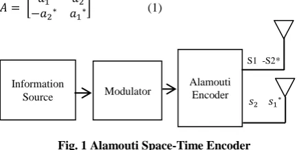
Diversity in MIMO leads to link reliability between the transmitter and receiver for a given data rate, which can be achieved in multiple dimensions such as space, frequency and time. In the transmit diversity scheme space-time block coding (STBC) is one of the most widely adopted transmission methods. This method transmits multiple copies of the information symbol over multiple independent channels in time and space. Due to the increase in link reliability, the channel fading decreases and increases in the robustness to co-channel interference. The data transmission with assured diversity achieved by the two transmit diversity schemes, one is the space-time block coding used in WiMAX and other is the space frequency block coding in 3GPP LTE with very low complexity symbol detector at the receiver side. The basic 2x2 Alamouti matrix in [1] is defined as
[image:1.595.316.534.471.580.2](1)
Fig. 1 Alamouti Space-Time Encoder
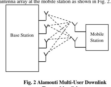
The multi-user STBC scheme adopts Alamouti structure due to its simplicity to transmit information symbols which increase the diversity order. An STBC is also represented in matrix form in which row represents a time slot and each column represents one antenna transmission. The transmitted signals are traversing through multipath in air media with scattering, reflection and refraction. The multiple copies are received at the receiver which may be corrupted due to thermal noise in the receiver. Some of the copies of the received data may be better than the others from the multiple copies, which help to decode the data correctly at the receiver.The advantage of space-time block coding is that it combines the multiple copies of the received signal and extract as much as information from each. A typical block diagram of the Alamouti space- time encoder is shown in the Fig 1. The data rate can be enhanced in multi-user STBC in the down link scenario where a base station (BS) uses two antenna arrays to transmit data to single
S1 -S2*
Modulator Alamouti Encoder Information
antenna array at the mobile station as shown in Fig. 2.
Fig. 2 Alamouti Multi-User Downlink Transmition Scheme
3.
LINEAR MIMO DECODERS
Zero-forcing (ZF) and Linear Minimum Mean Square Error (LMMSE) are linear decoders most widely used decoders in MIMO systems due to its low complexity. LMMSE performance better than the ZF decoder as noise factor is taken into consideration. In LMMSE detector the receiver symbol y is multiplied with a linear filter as
- (2) which involves the pre-calculation of an equalization matrix W
- (3) Here, σ2 is the noise variance. The computation of W needs to complete as soon as possible because without W symbol detection will not start. The computation of W is channel rate instead of symbol rate computation, hence W needs to be computed only once during the channel coherence time. The received symbol y has to be stored in a buffer until the W is available which adds the memory cost in the system. The calculations of W involve predominantly matrix inversion and matrix multiplication. The variation in the wireless channel will determine the frequency of matrix manipulation. Here we have considered the channel matrix H is of 4x4 size considering two user 2x2 STBC MIMO-OFDM based WiMAX system with the channel bandwidth 5 MHz, 512 subcarrier and carrier frequency f is 2.4 GHz. If the mobile handset moving with speed 60 Km/hr then based on the following formula the maximum Doppler shift fm is 139 Hz.
(4)
The formula for estimating the channel coherence time is defined in [2] as
(5)
For the Doppler shift of 139 Hz the coherence time Tcto be 8ms. During the estimation of the channel matrix the mobile is considered as stationary, hence it will not change drastically within the coherence time. The channel estimation and the channel preprocessing task have to be finished before the detection starts.
4.
MATRIX INVERSION FOR MIMO
DECODING
In the equation (3) W represents the equalization matrix. It involves the matrix inversion and matrix multiplication. For small matrices, a matrix inversion technique used is a direct analytic matrix inversion which is less complex and easy to implement. For bigger matrix, QR decomposition is a
traditionally used decomposition of the original matrix to generate a unitary matrix Q and upper triangular matrix R. The inverse matrix of Q is simply its hermitian transpose and the inverse matrix of R can be computed by using back substitution. Other than QR decomposition the available algorithms for matrix inversion are Strassen, Strassen-Newton, Gaussian elimination, Gauss-Jorden, LU decomposition, Cholesky decomposition etc.[3] But disadvantage of these algorithms they require square root operation which is having high computational complexity. However, Squared Givens Rotation (SGR) developed to reduce the square root operation, but this also has the drawback that it cannot handle the situation when zeros occurs on diagonal element. To overcome this drawback Modified SGR (MSGR) proposed, but many division operations are involved in this algorithm [4]. The Cholesky decomposition method requires positive definite matrix to ensure the argument of the square root is non-negative. So, a faster way to compute matrix inversion is to partioning the bigger matrix into four smaller matrices. This method is known as blockwise analytic matrix inversion. For example, to calculate the inverse of 4x4 matrix X, it is first divided into four sub-matrices
The blockwise analytic matrix inversion (BAMI) is more suitable as compared to the direct analytic matrix inversion as the least number of subtraction operations, which will avoid the possibility of cancellation. So, the blockwise analytic matrix inversion is an alternate method for the QR decomposition to calculate the matrix inversion of 4x4 matrix. For the small 2x2 and 3x3 matrices the direct analytic approach is preferred [5]. In this paper, the adopted matrix inversion is based on BAMI and the special structure of Alamouti. This method is known as Alamouti blockwise analytic matrix inversion (ABAMI), which significantly reduces the amount of computation needed to invert 4x4 matrix. The inversion of 2x2 Almouti matrix presented in equation (1) can be computed as follows
5.
MATRIX COMPUTATION OF
EQUALIZATION COEFFICIENT
MATRIX ‘W’
A general MIMO decoder system with nt transmit antennas
and nr receiving antennas is divided into two parts, namely
channel preprocessing and the symbol detection. The channel preprocessing units pre-calculate the equalization coefficient matrices W from the estimated channel matrix H. The equalization coefficient matrices W is given by the equation (3) where H is a channel matrix of size nr x nt. The
implementation of this equalization coefficient matrix W is divided into three parts such as
Computation of B
Computation of B inversion
Multiplication of B-1 and HH
5.1
Computation of B
The matrix B involves multiplication of H hermitian matrix and H matrix. The matrix H has the complex values. The size of the H matrix is normally 2x2 or 4x4. Here, for implementation H matrix is considered of size 4x4. For small size matrices, to obtain the matrix inversion with higher speed direct analytic matrix inversion is used. For STBC scheme the 4x4 MIMO channel matrix H with complex value is given by
For linear MMSE detection, we have
These computations give and as real values, whereas and are complex values. The computation of B involves , , and values. From above equation, it is observed that , , and computation requires complex multipliers and adders. These computations can be done in two different ways.
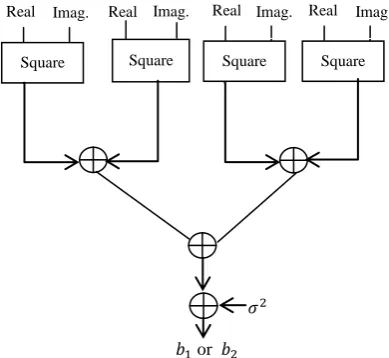
Method – I: In this method , , and are computed parallely. The equations of and involves single input and its conjugate in the product terms. To obtain the product terms in and square unit is used. The equation of and involves two different inputs in each product term, so to obtain these product terms complex multipliers are used. To obtain the complex conjugate of input 2s complement unit is used. To find out the all four values parallely, four multiply and accumulate units are required. The following Fig.3 shows the schematic diagram for the computations of and .
[image:3.595.65.260.533.712.2]
or
Fig. 3 Schematic Diagram for the computation of b1 and b2
R I R I R I R I R I R I R I R I
Real part of b3 and b4 Imaginary part of b3 and b4
Fig. 4 MAC unit for the computation of b3 and b4
The above Fig.4 shows the schematic diagram for the computations of and . The square unit used for and
computation requires two multiplier and one adder. The complex multiplier uses four multipliers and two adders. The multiply and accumulation unit of or requires a more number of adders as compared to or multiply and accumulate (MAC) unit. The number of adders are less in or computation because all the product terms are real. On the contrary, as or are complex, hence separate adders being required for the real part and imaginary part of data.
Method – II: In method I, , , and are computed parallely. The equations of and as well as the equations of and are similar. So instead of using separate unit for
and , a single unit can be used with the selection logic for input. Similarly for and computation single unit can be used with selection logic. This method reduces the number of square unit and complex multipliers. The following Fig. 5 shows the schematic diagram for the computation of or .
σ2
b1 or b2
Fig. 5 Schematic diagram for computation of b1 or b2 Complex
Multiplier
Complex Multiplier
Complex Multiplier
Complex Multiplier
Imag. Real
Real Real
Square Real
Square Imag.
Square Square Real Imag. Imag.
2s Complement Block
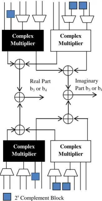
Fig. 6 MAC unit for computation of b3 or b4
The above logic reduces four square units at the cost of the eight multiplexer in and computation. Similarly, four complex multipliers are reduced with increase in eight multiplexers in and computation. The above Fig.6 shows the schematic diagram of and computation.
5.1.1
Operations Involved in Computation of
Matrix B
[image:4.595.351.471.201.407.2]The following Table 1 shows the various operations involved in the computation of matrix B
Table 1: Complex Floating-point Instructions
Name Description
Complex Squared absolute
Complex Multiply Two’s Complement
40 Bit Adder
and each are of
40 bit
5.1.2
Numeric Representation
The computation of matrix B involves the data representation in fixed point format. The fixed point format uses the 20 bit representation in which 8 bits are used for representing the integer and 12 bits are used for the fractional data. For increasing accuracy, multiplier output 40 bits is processed as it is. Hence, 40 bit adder is used to add the output of multiplier.
5.2
Computation of Matrix Inversion of B
The Hermitian and Alamouti structure of σ provide simplicity for computing matrix inversion.
σ
where ,
This matrix inversion involves multiplication, addition and inverse operations. The division operation is performed by using divider which uses 16 bit data as dividend and a divider. To perform the divider operation, if the dividend is smaller than the divider then the division operation gives a result as quotient value approximately zero. To avoid this problem, common scaling factor of 100 is used for c1, c2, c3 and c4.
However, due to this magnitude value increase by the same factor.
5.3
Computation of the Equalization
Factor W
The computation of matrix inversion discussed in the previous part which involves the operations like square, complex multiplier, adder etc. To obtain the equalization term W, multiplication of two matrices is done i.e. .
and
Imaginary Part b3 or b4
Real Part b3 or b4
Complex Multiplier
Complex Multiplier
Complex Multiplier
Fig. 7 Computation of Equalization Term W
The above Fig. 7 shows the schematic diagram for the computation of the equalization matrix W. The multiplication of B-1 and HH includes real multiplier, complex multiplier, 4:1 multiplexer and adder. The H and B-1 matrix is of size 4x4 hence the multiplication of these two matrices results into 16 complex values. To determine the all 16 values only four circuits of multiply and accumulate units are used. The use of 4:1 multiplexer selects the different inputs and passed to the multiplier. This additional selection logic reduces 12 MAC unit. This reduction in hardware increases the latency. The single MAC unit calculates four elements of one row; such four MAC units are used to find all 16 values.
6.
IMPLEMENTATION
The 4x4 LMMSE MIMO decoder design was successfully synthesized, placed, routed and verified on Xilinx Virtex- 4 series part. For the FPGA implementation Xilinx ISE and core generator is used to synthesize the data path components. Here, the matrix to be inverted is the size of 4x4 and the data is presented in 20 bit fixed point format which is usually chosen for the mobile handset to improve the area efficiency. Matrix inversion computation involves multiplication, division, addition and subtraction. Following Table 2 shows implementation results of the LMMSE decoder including the resource utilization from the synthesis report.
Table 2: FPGA Implementation Result
Method-I Method-II
FPGA Type Virtex4 Virtex4
Number of Parallel Streams 4 4
Datatype Fixed Fixed
Wordlength (bits) 20 20
Number of Slices 6189 4149
Number of DSP48s 61 37
Cycles to compute W
(LMMSE) 20 21
Latency/subcarrier 48.52ns 48.64ns
[image:5.595.310.547.71.134.2]Frequency (MHz) 130 128
Table 3: FPGA Implementation Result of other work for Comparison
Ref.[9] Ref.[8] Ref.[7] Ref.[6]
FPGA Type Virtex4 Virtex4 Virtex2 Virtex2
Number of Parallel Streams
4 4 1 1
Datatype floating Fixed Fixed
Wordlength
(bits) 20 20 16 12 Number of
Slices 8516 9474 16805 4400 Number of
DSP48s 0 0 44 0
Cycles to compute W
(LMMSE)
120 120 66 100
Latency/
subcarrier
0.188μs 0.563μs 45μs --
Frequency
(MHz) 120 120 66 100
As from the above Table 3 it seems that the our 20 bit fixed point implementation consumes less area and faster as compared to the synthesis result present in [6], [7], [8] and [9].
7.
CONCLUSION
In this paper, we have presented a simple and efficient matrix inversion method for small matrices of size 4x4. The implementation results are compared with other existing solutions in Table 3. According to the comparison our solution requires less resources, hence consumes a less silicon area and achieves high performance. Our implementation is faster as compared to the solution proposed in the prior work. After computing matrix inversion, equalization matrix W is obtained by multiplying the inversion matrix with hermitian matrix. The multiplexers are used to pass the different inputs which reduces the hardware of the MAC unit to 25%. The hardware resources in Method-I is 75% of Ref.[9] and in Method-II hardware resources used are 50% of Ref. [9].
8.
REFERENCES
[1] S. M. Alamouti, “A simple transmit diversity technique for wireless communications,” IEEE Journal on Sel. Areas in Comm., vol. 16, no. 8, pp. 451–1458, Oct. 1998. [2] J. Andrews, A. Ghosh and R. Muhamed, “ Fundamentals
of WiMAX: Understanding Broadband Wireless Networking”, Prentice all, Mar 007.
[3] Golub, Gene . and Charles F. Van Loan, “Matrix Computations”, Vol. 3, J U Press, 2012.
[4] Lei Ma; Kevin Dickson; John McAllister; John
R
Real Multiplier
Real Multiplier
Complex Multiplier
Complex Multiplier
McCanny, “QR Decompostion based matrix inversion for high performance embedded M MO receivers”, EEE Transactions on Signal Processing Volume 59, Issue -4 , April 2011, pp 1858 – 1867.
[5] D. Wu, J. Eilert, D. Liu, D. Wang, N. AI-Dhahir and H. Minn, “Fast Complex Valued Matrix nversion for Multi-User STBC-M MO Decoding”, Proc. EEE SVLS , 2007.
[6] F. Edman, V. Ӧwall, “ A Scalable Pipelined Complex Valued Matrix nversion Architecture”, Proc. EEE ISCAS, 2005.
[7] M. Myllylӓ, J. intikka, J. R. Cavallaro and M. Junti, M. Limingoja, A. Byman, “Complexity Analysis of MMSE Detector Architectures for M MO OFDM Systems”, Proc. 39th Asilomer Conference on Signals, Systems and Computers, 2005.
[8] J. Eilert, D. Wu, D. Liu, “ mplementation of a Programmable Linear MMSE Detector for MIMO-OFDM”, invited paper, EEE CASSP 008.