© 2019, IRJET | Impact Factor value: 7.211 | ISO 9001:2008 Certified Journal | Page 5212
IMPLEMENTATION OF MULTILEVEL INVERTER USING SOLAR PV ARRAY
FOR RENEWABLE ENERGY APPLICATIONS
Sangavi. R
1, Sindhu. R
2, Vinotha. M
3, Payani. M
41,2,3
PG Scholar, Department of Electrical and Electronics Engineering, Sri Ramakrishna Engineering College,
Coimbatore, Tamil Nadu, India
4
Assistant Professor, Department of Electrical and Electronics Engineering, Sri Ramakrishna Engineering College,
Coimbatore, Tamil Nadu, India
---***---
Abstract - Solar vitality is a sustainable power sourcethat is found richly in nature. It is environmentally friendly power vitality that can be used all through day, in this way greatest vitality needs to caught from the board. MPPT calculation is consolidated to catch greatest vitality. A multilevel inverter is a power electronic converter that incorporates an ideal yield voltage from a few dimensions of dc voltages of dc voltages as sources of info. With an expanding number of dc voltage source, the sinusoidal waveform is acquired by the yield voltage, while utilizing a principal recurrence exchanging plan. The benefit of multilevel inverter is extremely little yield voltage, results in higher yield quality and lower exchanging misfortunes. This paper proposes a MPPT controller based sunlight based power age framework, which comprise of dc/dc converter and another nine-level inverter.
Keywords: MPPT, Multilevel Inverter, PWM inverter, sun oriented vitality.
1. INTRODUCTION
One of the real worries in the power segment is the
everyday expanding power request yet the
inaccessibility of enough assets to fulfill the power need utilizing the customary vitality sources. Along these lines, the improvement of high static increase (G) dc– dc converters is a vital structure because of present's interest of low voltage inexhaustible sources like sun based PV, wind vitality, energy component applications in versatile electronic hardware, uninterruptable power supply, and battery fueled gear. Traditional non disconnected Boost converter gives restricted voltage addition of about G=5 with obligation proportion of 0.8 and typically can work with a satisfactory static and dynamic execution. A dc– dc converter working with a static increase go until G = 5 is viewed as a standard static addition, a static addition extend higher than G = 10 is viewed as a high static increase arrangement and an activity with static addition higher than G = 20 is viewed as an exceptionally high static addition.
The base topology is here considered as a SEPIC DC-DC converter. Be that as it may, it creates restricted addition same as lift converter likewise has high information swell current. So to expand the addition
above systems is utilized and from that two topologies are inferred that are converter without attractive coupling and with attractive coupling.
Dc-dc converters are broadly utilized in directed exchanged mode dc control supplies and in dc engine drive applications. The contribution to these converters is regularly an unregulated dc voltage, which is acquired by redressing the line voltage and it will in this manner change because of varieties of the line voltages. Exchanged mode dc-dc converters are utilized to change over this unregulated dc contribution to a controlled dc yield at an ideal voltage level. The ongoing development of battery fueled applications and low voltage stockpiling components are expanding the interest of effective advance up dc– dc converters. Normal applications are in flexible speed drives, switch-mode control supplies, continuous power supplies, and utility interface with nonconventional vitality sources, battery vitality stockpiling frameworks, battery charging for electric vehicles, and power supplies for media transmission frameworks and so on.
A standout amongst the most prevalent MULTILEVEL inverter topologies is the fell H connect (CHB) topology. So as to execute a five-level inverter, a CHB circuit would require 24 switches. This paper introduces an other five-level inverter topology with 15 switches which is a financially savvy option in contrast to the ordinary five-level CHB inverter. This paper additionally shows a successful technique for execution of vector control of a PMSM with this decreased switch five-level inverter topology. A similar examination of the vector control with traditional two-level SPWM and utilizing the decreased switch five-level inverter has been done dependent on the recreations did on the proposed drive framework in MATLAB/Simulink condition.
2. CAPACITY AND DESIGN OF THE PROPOSED
PROTOTYPE
© 2019, IRJET | Impact Factor value: 7.211 | ISO 9001:2008 Certified Journal | Page 5213
warmth to heat up water, and sun oriented PVframeworks that convert daylight legitimately into power.
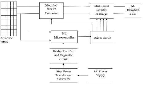
[image:2.595.42.277.223.361.2]At the point when the PV modules are presented to daylight, they create direct flow ("DC") power. An inverter at that point changes over the DC into rotating flow ("AC") power, so it can sustain into one of the structure's AC appropriation sheets ("ACDB") without influencing the nature of intensity supply.
Fig 1: Block graph of proposed framework
3. MODIFIED SEPIC CONVERTER
In established SEPIC converter give low addition about of five with high swell current additionally have switch voltage which is almost 50% of yield voltage. To build gain alteration is done as diode Dm and capacitor Cm in the middle of inductor and switch. This adjustment cell called Voltage multiplier Cell. So by achieving this cell, adjusted converter give gain twice of that traditional SEPIC converter.
The power circuit of changed SEPIC converter is available. The static addition of the SEPIC converter is an either venture up or venture down. In which the switch voltage is equivalent to the total of info and yield voltage. In some application the whole of the info voltage and yield voltage is equivalent to the Switch voltage and static addition is lower than the exemplary lift converter. By including two segment for example diode and DM and Capacitor CM in the SEPIC converter. With this alteration numerous qualities are change with this converter. The static addition of the modified SEPIC converter is expanded by twofold than traditional lift converter with the high obligation proportion. Be that as it may, for all intents and purposes the confinement of this converter is we can't surpass obligation proportion above 0.85. Consider converter CCM mode it incorporates two phases. For investigation accept all capacitors as a voltage source and semiconductors to be perfect. 1)First Stage [t0-t1] in this stage turn S is kills at a moment t0 and the diode DM and DO are forward
one-sided. The put away vitality in L1 gets exchange to the yield through the CS and DO and furthermore it gets exchange to CM through DM. Because of this the switch voltage is equivalent to the Cm voltage. Vitality put away in L2 gets exchange to yield.
2) Second Stage [t1-t2] in this stage switch turns-on at a moment t1 the diodes DM and DO gets square and vitality gets store in the inductors L1 and L2. Info inductor L1 accuses of information voltage and inductor L2 accuses of the voltage VCM - VCS. The greatest voltage in all diodes and the power change is equivalent to the CM capacitor voltage. The aggregate of the CS and CM capacitors voltage is equivalent yield voltage. Info current is equivalent to average L1 inductor current, and yield current is equivalent to the normal L2 inductor current. At the enduring state the static addition of the proposed converter can be acquired considering invalid the normal inductors voltage and it is displayed in (1) thinking about the CCM task. The static increase of the proposed converter is higher than the acquired with the traditional lift.
4. MULTI-LEVEL H-BRIDGE INVERTER
Multilevel inverters keep on accepting increasingly more consideration in light of their high voltage activity ability, low exchanging misfortunes, high productivity and low yield of Electro Magnetic Interference (EMI). The term MULTILEVEL begins with the three-level inverter presented by Nabae et al (1981).
A multilevel inverter has a few points of interest over a regular two-level inverter that utilizes high exchanging recurrence beat width regulation (PWM). The most alluring highlights of a multilevel inverter are as per the following:
1) They can create yield voltages with incredibly low twisting and lower dv/dt.
2) They draw input current with low contortion.
3) They create littler normal mode (CM) voltage. 4) They can work with a lower exchanging recurrence.
TOPOLOGY OF MULTILEVEL INVERTERS
© 2019, IRJET | Impact Factor value: 7.211 | ISO 9001:2008 Certified Journal | Page 5214
Fig 2: Classification of Multi Level InvertersThe diode-clipped inverter is otherwise called the nonpartisan point braced inverter (NPC) which was presented by Nabae et al (1981). The diode-clipped inverter comprises of two sets of arrangement switches (upper and lower) in parallel with two arrangement capacitors where the anode of the upper diode is associated with the midpoint (impartial) of the capacitors and its cathode to the midpoint of the upper pair of switches; the cathode of the lower diode is associated with the midpoint of the capacitors and partitions the primary DC voltage into littler voltages, which is appeared in Figure 2.2. The NPC utilizes a solitary dc transport that is subdivided into various voltage levels by an arrangement series of capacitors. For a three-level diode-clipped inverter if the point O is taken as the ground reference, the yield voltage has three states 0, 1/2Vdc and - 1/2Vdc . The line-line voltages of two legs with the capacitors are +Vdc, 1/2Vdc 0 - 1/2Vdc, - Vdc. Three stages are important to produce a three-stage voltage.
5. MPPT CONTROLLER
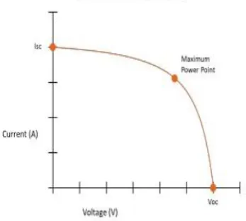
[image:3.595.347.521.105.261.2]PWM and MPPT are the two unique sorts of charging techniques sunlight based charge controllers can use to charge batteries from a sun based cluster/board. The two advancements are broadly utilized in the off-framework sun oriented industry and are both incredible alternatives for effectively charging your battery. The choice to utilize PWM or MPPT guideline isn't simply founded on which control charging technique is "better" than the other. Also, it includes figuring out which kind of controller will work best in your framework's plan. The power bend is critical in light of the fact that it expresses the normal power age of the board dependent on the mix voltage ("V") and current ("I") produced by the board. The ideal proportion of current to voltage to deliver the most power is known as the "Greatest Power Point" (MPPT). The MPPT will change progressively for the duration of the day relying upon light conditions.
Fig 3: VI Characteristics of PV Panel
The C2000 Piccolo Microcontroller has a set structure. The power phases of the microcontroller are a solitary stage support arrange with MPPT ability, a SEPIC battery accusing phase of MPPT capacity, and a framework tie-proficient DC/AC inverter organize fit for yielding 24VAC. The structure that is of most capacity in our framework would be the board emulator utilizing DC/DC control organize in light of the fact that it enables us to assess MPPT under various shading states of the PV board. The microcontroller in intersection with Control Suite and Code Composer Studio enables us to execute distinctive MPPT calculations and deal with a PV application. Diverse calculations can be customized to find most extreme power purpose of a board including Perturb and Observe (P&O) and gradual conductance. The framework configuration incorporates working with the two kinds of MPPT. Another capacity the microcontroller could be customized for is to be utilized as a carefully controlled sunlight based MPPT DC-DC converter.
6. PIC MICROCONTROLLER
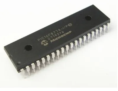
The PIC microcontroller PIC16f877a is a standout amongst the most prestigious microcontrollers in the business. This controller is helpful to utilize, the coding or programming of this controller is likewise simpler. One of the primary favorable circumstances is that it very well may be compose eradicate however many occasions as would be prudent on the grounds that it utilize FLASH memory innovation. It has an all out number of 40 pins and there are 33 pins for info and yield. PIC16F877A is utilized in numerous PIC microcontroller ventures. PIC16F877A likewise have numerous applications in computerized hardware circuits.
© 2019, IRJET | Impact Factor value: 7.211 | ISO 9001:2008 Certified Journal | Page 5215
likewise included in it which makes it conceivable to [image:4.595.59.259.221.374.2]store a portion of the data for all time like transmitter codes and beneficiary frequencies and some other related information. The expense of this controller is low and its taking care of is additionally simple. It's adaptable and can be utilized in zones where microcontrollers have never been utilized as in coprocessor applications and clock capacities and so forth you may likewise prefer to check total rundown of PIC microcontroller instructional exercises.
Fig 4: PIC MicroController
As we have contemplated 5 information and yield ports to be specific PORTA, PORTB, PORTC, PORTD and PORTE which can be computerized just as simple. We will design them as indicated by our necessities. Be that as it may, if there should arise an occurrence of simple mode, the pins or the ports can just go about as information sources. There is a worked in A to D converter which is utilized in such cases. Multiplexer circuits are likewise utilized.
7. DRIVER CIRCUIT
Segregated MOSFET driver TLP250 working
In this article I will examine secluded MOSFET driver TLP250. MOSFET driver TL250 like other MOSFET drivers have input stage and yield organize. It additionally have control supply arrangement. TLP250 is progressively appropriate for MOSFET and IGBT. The fundamental contrast among TLP250 and other MOSFET drivers is that TLP250 MOSFET driver is optically disengaged. Its mean information and yield of TLP250 MOSFET driver is segregated from one another. Its works like an optocoupler. Info organize has a light radiating diode and yield arrange have photograph diode. At whatever point input arrange LED light falls on yield organize photograph finder diode, yield turns out to be high.Pin number 6 and 7. Command hierarchy arrangement of two transistors is utilized in TLP250. In the event of high info , yield turns out to be high with yield voltage equivalent to supply voltage and if there
should be an occurrence of low information, yield become low with yield voltage level equivalent to ground.
SSTLP250 as a low side MOSFET driver
Circuit graph of low side MOSFET driver utilizing tlp250 is appeared as follows. In this circuit outline, tlp250 is utilized as non upsetting low side MOSFET driver. You ought to interface an electrolytic capacitor of significant worth 0.47uf between power supplies. It give assurance to tlp250 by giving settle voltage to IC.
As appeared in figure above info is drive flag that drives the yield. Vin is as per flag ground. It ought not be associated with supply ground and yield ground. It is unmistakably appeared above figure TLP250 and burden ground is referenced to the power ground and it is segregated from information flag reference ground.
At the point when input is high, MOSFET Q1 get high flag from TLP250 and it is driven by power supply and current courses through the heap. At the point when input is low, MOSFET Q1 get low flag from TLP250 yield Pin and MOSFET Q1 stays off and there is no present stream to stack. Estimation of supply voltage extends between 10-15 volt. Information resistor at door of MOSFET is utilized rely upon sufficiency of info flag. Typically input flag is given through microcontroller and microcontroller input flag level is in the request of 5 volt. Capacitor C1 is utilized as decoupling capacitor.
8. CONCLUSION
© 2019, IRJET | Impact Factor value: 7.211 | ISO 9001:2008 Certified Journal | Page 5216
based power age framework can successfully follow themost extreme intensity of sunlight based cell cluster.
9. REFERENCES
[1] C. W. Li, X. He, “Review of Non-Isolated High Step-Up DC/DC Converters in Photovoltaic Grid-Connected Applications”, IEEE Transactions on Industrial Electronics, vol. 58, no. 4, pp.1239-1250, April 2011.
[2] C. S. B. Kjaer, J. K. Pedersen and F. Blaabjerg, “A Review of Single-Phase Grid-Connected Inverters for
Photovoltaic Modules”, IEEE Transactions on Industry Applications, vol. 41, no. 5, pp. 1292-1306, September 2005.
[3] D. Meneses, F. Blaabjerg, O. Garcia and J. A. Cobos, “Review and Comparison of Step-Up Transformerless Topologies for Photovoltaic AC-Module Application”, IEEE Transactions on Power Electronics, vol. 28, no. 6, pp. 2649- 2663, June 2013.