A model driven approach to
modernizing legacy information
systems
Author:
Sander
Goos
S0113409
Supervisors:
Dr. Ir. M.
van Keulen
Dr. I.
Kurtev
Ir. F.
Wijnhout
Ing. J.
Flokstra
Master Thesis
University of Twente
in collaboration with
Thinkwise Software Factory B.V.
A model driven approach to
modernizing legacy information systems
A thesis submitted to the faculty of Electrical Engineering, Mathematics and Computer Science, University of Twente, the Netherlands in partial fulfillment
of the requirements for the degree of
Master of Science in Computer Science
with specialization
Information Systems Engineering
Department of Computer Science,
University of Twente
the Netherlands
Abstract
We propose a general method for the modernization of legacy information sys-tems, by transforming these systems into model driven systems. To accomplish a transformation into a model driven system, first a model is extracted from the legacy system. This model is then transformed into a model driven sys-tem, using Model Driven Engineering. This means that for the transformation, a model is constructed and an MDE tool is used to generate the executable transformation code for it. The method is not limited to the data-model of the legacy system, but is instead applicable to the entire system. Furthermore, the method has a best-effort character, and allows for automatic traceability. By means of a pilot modernization project, the method is validated with the Thinkwise Software Factory as the MDE tool.
Acknowledgements
I would like to thank a few people who helped me during the course of this project, and have made it an interesting time for me. First of all, I want to thank my supervisors: Maurice, Frank, Ivan and Jan. The meetings we had were always really motivating and it was a pleasure to work with them. Maurice, in particular, has taught me a lot during the project, and was enthusiastic about the project from the start. I also want to thank my employer Thinkwise, and in particular Victor, for the great amount of confidence in me and for the freedom I had during the project. I thank my colleagues at Thinkwise, and my fellow students on the third floor, who contributed to a fun and productive working environment. I thank my girlfriend, Angelique, who has been very patient and supportive during busy times. Finally, I thank my family and friends who have always supported me during the course of my study and have motivated me to pursue.
Contents
Abstract i
Acknowledgements iii
1 Introduction 1
1.1 Context . . . 2
1.1.1 Legacy systems . . . 2
1.1.2 Model Driven Engineering . . . 3
1.1.3 Model transformations . . . 4
1.2 The problem . . . 5
1.3 Research questions . . . 6
1.4 Validation . . . 7
1.5 Contribution . . . 8
1.6 Overview . . . 8
2 Related Work 9 2.1 Dealing with legacy systems . . . 9
2.1.1 Transformation strategies . . . 9
2.1.2 Deployment strategies . . . 9
2.2 Model Driven Architecture . . . 10
2.2.1 Meta-Object Facility . . . 10
2.2.2 ATL . . . 11
2.3 Reverse engineering . . . 12
2.3.1 Database reverse engineering . . . 12
2.3.2 Model discovery . . . 12
2.4 Transformation approaches . . . 12
2.4.1 Architecture driven modernization . . . 12
2.4.2 ModelGen . . . 13
2.5 Conclusion . . . 14
3 General approach 17 3.1 Technical spaces . . . 18
3.2 Exogenous model transformation with MDE . . . 19
3.3 Metaphorical example . . . 20
3.4 Conclusion . . . 20
4 Modelling a legacy system 23 4.1 Different ways to express information . . . 23
vi CONTENTS
4.2 Models and meta-models . . . 25
4.3 Generic or specific meta-model . . . 26
4.4 Knowledge Discovery Meta-model . . . 26
4.5 Conclusion . . . 27
5 Modelling model transformations 29 5.1 Why model the transformation? . . . 29
5.2 Requirements . . . 30
5.3 Schema mapping . . . 31
5.4 Cardinality . . . 32
5.5 Example mappings . . . 34
5.5.1 From meta-model A to meta-model B . . . 35
5.5.2 From meta-model B to meta-model A . . . 37
5.6 Transformation meta-model . . . 38
5.6.1 Mapping relations . . . 40
5.6.2 Executability and traceability . . . 40
5.7 Conclusion . . . 41
6 Thinkwise Software Factory 43 6.1 Software Factory meta-model . . . 43
6.1.1 Base projects . . . 45
6.1.2 Meta-modelling . . . 45
6.2 Functionality . . . 46
6.3 Graphical User Interface . . . 46
6.4 Conclusion . . . 47
7 Validation 49 7.1 Pilot project . . . 52
7.2 Access Upcycler . . . 53
7.2.1 Access meta-model . . . 53
7.2.2 Access model extraction . . . 55
7.2.3 Routines pre-processor . . . 56
7.2.4 Transformation model . . . 56
7.3 Framework . . . 60
7.3.1 General entities . . . 60
7.3.2 Transformation generation . . . 60
7.4 Pilot results . . . 63
7.4.1 Model extraction . . . 63
7.4.2 Routines pre-processor . . . 65
7.4.3 Transformation . . . 65
7.4.4 Traceability . . . 65
7.5 Conclusions . . . 69
8 Conclusions and future work 71 8.1 Conclusions . . . 71
Chapter 1
Introduction
Imagine a classroom full of physics students, waiting for their first lecture to commence. The teacher closes the door and walks to the front of the classroom. “Good morning class, today’s lecture is about mechanics.”, he announces. “A very important scientist in this field was Sir Isaac Newton. According to my colleagues, he developed some exciting and revolutionary laws – and it is all written down in this book.” The teacher holds up the Principia Mathematica from 1726. “Unfortunately however,” he continues, “it is all written in Latin!”. Since Latin is not part of the curriculum, the students all look confused at each other, and one asks: “Do we now first have to learn Latin?”. “No, don’t worry...” the teacher replied, “...I don’t understand Latin myself either. Besides, when something is so old that it is written in Latin, how can it possibly apply to today’s world?! No, I think it will be better if we create our own, more modern, theories. Will you all join me to the apple tree in the garden? I am sure it wouldn’t be too hard to figure it out...”.
What do you think of the approach of this teacher? Absurd? Naive? We think most people would agree that the teacher greatly underestimates the redevelop-ment of the theories, and that translating the old works would be a lot wiser. But when this seems so obvious, then it might be surprising that in software modernization projects, redevelopment is not uncommon. Legacy computer sys-tems often are built with architectures and (programming-)languages no longer used or learned by programmers. While the knowledge in these systems might not be so unique as Newton’s Principia Mathematica, a lot of systems have taken years of development – and therefore do represent great value. When these systems become too costly to maintain, or when new technologies need to be incorporated, they need to be replaced with modern variants. However, since the modern programmers do not fully understand the legacy system, not rarely, it seems easier to redevelop the system from scratch in a new language.
In [1], Ulrich states that the knowledge captured in the legacy system should serve as an important resource in modernization projects. However, extracting and using that “knowledge” from a legacy system also requires effort. Therefore, the author provides means for building a business case for the transformation of legacy systems. The business case should be used to determine whether
2 CHAPTER 1. INTRODUCTION
transformation is the right strategy in a modernization project. By transforming parts of the original system, the value and knowledge incorporated in them can be recycled. Since the target platform typically also has more technological advantages than the source platform, we refer to this process as: Upcycling. Upcycling in general is a form of recycling (waste materials / useless products) where the result is of a higher quality than the original product. In our case, the original product is a legacy system and the result is a new system on a new platform. The question of how to do this in a general way is interesting, and the question to what extent we can automate this, even more. In this thesis we answer these questions by developing such a general method and validate it with a prototype.
The following sections give a general introduction to the thesis. First, the context of the thesis is discussed, after which the problem is elaborated. When the problem is clarified, we advance in stating the focus by formulating the goals of the project. Then, the method of validation is treated, and we finish the chapter with the contribution of the thesis.
1.1
Context
The problem context in this thesis is that of legacy information systems and Model Driven Engineering, or MDE. The legacy system is our source system and serves as the initial starting point. The goal is to transform this system in such a way that it can be maintained and developed further with MDE. In the remainder of this thesis, such a system is referred to as a model driven system. The following subsections serve as a basic survey of these concepts and introduce the terminology that is used in the remainder of the thesis.
1.1.1
Legacy systems
Since a central subject in our research is a legacy information system [2], an explanation about what we mean by that is in place. The definition below for a legacy system is borrowed from Wikipedia [3]:
A legacy system is an old method, technology, computer system, or application program that continues to be used, typically because it still functions for the users’ needs, even though newer technology or more efficient methods of performing a task are now available.
In our work, we look at legacy systems that need to be replaced. There are various reasons why a company wants to replace legacy systems, for instance:
• Maintenance costs get too high.
• A new module is needed, but there are no programmers any more in the company that know enough about the system to be able to modify and extend it.
1.1. CONTEXT 3
• The legacy system does not scale well enough with the growth of the company.
• It is not easy to connect or integrate the legacy system with other systems in or outside the company.
The legacy systems on which we focus, are legacyinformationsystems. Systems with their primary purpose being the storage and retrieval of business data. This does not mean that these systems do not perform operations or computations. Instead, the majority of legacy information systems typically have a considerate amount of business logic contained in them. It is just that theirprimarygoal is to store and retrieve information – which is why we call them legacy information systems. We transform these systems into model driven systems, using Model Driven Engineering.
1.1.2
Model Driven Engineering
Model Driven Engineering [4] is a discipline that followed from OMG’s Model Driven Architecture, or MDA [5, 6]. MDA is a method where models are ex-tensively used in the design of software systems. As can be seen from other branches, models can provide crucial insights in the system before it is imple-mented. They serve as a clear guideline for the implementers and also allow to detect possible faults early.
Before we continue, let us clarify what we mean with a model. In most design projects, a model is used to represent the system or building that is not yet created. In construction, for instance, a cardboard architectural model is created before the construction of the building begins. This model, which is a lot smaller than the actual building, provides great insight in what the actual building will look like. Next to a physical model, a mathematical model of the construction can be very useful too. Such a model can be used to, for example, predict stability issues. In software engineering, this is no different. A model represents the design of the system often in a more comprehensible abstract form than the system itself, and can also be used to make predictions about the system. Aside from the different aspects being modelled, a major difference in the physical architectural model, the mathematical model, and the software model, is the language used. The physical model has the “language” of cardboard and glue, the mathematical model: mathematics and the software model, for instance: UML (Unified Modeling Language).
The definition of a model from the MDA Guide [5] is as follows:
A model of a system is a description or specification of that system and its environment for some certain purpose. A model is often presented as a combination of drawings and text. The text may be in a modeling language or in a natural language.
4 CHAPTER 1. INTRODUCTION
A model only means something to a person when its meta-model is also known. For example, when someone never learned mathematics, a mathematical model makes no sense to him or her. Also, a construct in one meta-model can have a different meaning in another meta-model. This makes a model inextricably connected with its meta-model.
In earlier approaches to modelling in software development, the need keep the models up to date with the system, diminished once the system was opera-tional. Therefore, these models are bound to get out-of-sync, and run the risk of becoming legacy themselves. This can make them practically unusable in modernization projects. In Model Driven Engineering, or MDE, the model is actively used in the creation and maintenance of the system. In fact, the model is the primary place where changes are made to the system, i.e. the models are treated as first class entities. The entire system is generated or interpreted directly from the model describing it, making the model a complete definition of the system. The benefit of MDE is that the model and the system can no longer get out-of-sync, since they are tightly connected. The usefulness of this principle gets larger when the system gets larger. Imagine you need to change a certain behaviour of a large system when years of maintenance has passed since the first release. When there is a model of the system available, of which it is
guaranteed that it is in sync with the system, i.e. the system conforms to that model, this can be of much help in finding the appropriate modules, predict impact, and so on.
In the remainder of this thesis we use the term: MDE tool, to refer to the preferred tooling or development environment for Model Driven Engineering. We assume that the MDE tool uses a fixed meta-model, to which all the model need to conform to.
1.1.3
Model transformations
Since models are the primary elements of development in MDE, model trans-formations are very important. In the broadest sense, a model transformation is a process in which an existing model is used to create another model. Model transformations come in different forms.
1.2. THE PROBLEM 5
horizontal vertical endogenous Refactoring Formal refinement
exogenous Language Migration Code generation
Table 1.1: The two orthogonal dimensions of model transformations (copied from [7])
1.2
The problem
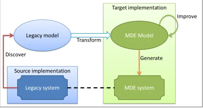
[image:13.595.104.359.124.165.2]Now that the context has been clarified in the previous section, let us focus on the problem at hand. Essentially, what we want to accomplish is to fill the model of an MDE tool with as much information as possible from the legacy system. After this, the MDE tool can be leveraged to improve the system, employ new technologies, provide integration with other systems, and so on. In figure 1.1, our goal is depicted schematically. In the lower left corner, the legacy system is shown and is considered to be our source system in the transformation. In the right part of the figure, a model driven system is shown and serves as the target system. Our goal to use MDE to perform the transformation from the source system to the target system, that is represented by the arrow with the question mark. Notice that the endpoint of the arrow is the model in the target implementation. The actual target system will then be generated from the model using the MDE tool at hand. Since the main goal is to modernize (and not necessarily change) the source system, it is important that the target system is similar or even equivalent to the source system. This is depicted with the dashed line between the source system and the target system in figure 1.1.
Figure 1.1: Schematic (simplified) overview of the goal.
6 CHAPTER 1. INTRODUCTION
be reverse engineered from the source code. Legacy systems also come in a wide variety, i.e. they are heterogeneous. This implies the need for much flexibility in the reverse engineering. Furthermore, we have to transform as much as possible from the source system in order to make the target system as equivalent as possible to the source system. This means not only the static structures (such as the data-model) should be transformed, but also the dynamic structures (such as the source code).
The notion of transformingas much as possible aims for a best-effort approach instead of all-or-nothing. This means that when something – for whatever reason – cannot be transformed to the target system, we accept this loss at first, create a reminder for this object in the target system, and continue with the parts of the system that can be transformed. At a later time, it should be possible to (perhaps manually) transform the remaining parts. This can be achieved by using proxy objects as the “reminders”. A proxy object consists of a reference to the actual object in the source system that could not be transformed. In this way, the target system has knowledge about all the objects in the source system, while only a part of these objects might actually be transformed. This prevents the need to analyse the source system again to determine untransformed objects in the future.
Finally, there needs to be some way to measure the equivalence of the target system with the source system. Since solving the equivalence problem for soft-ware systems is out of the scope of this thesis, we propose the use of traceability for measuring equivalence. For the traceability, we adopt the idea of “trace-ability as a model” from [8]. To address these problems, research questions are composed and presented in the next section.
1.3
Research questions
In this section we define the focus of the thesis. As was discussed in the pre-vious section, the main goal is to utilize MDE in the modernization of legacy information systems. We can break this goal down into two steps. The first step is to make the legacy system “model driven”, such that an MDE tool can work with it. The second step is to leverage the functionality of the MDE tool to further modernize the system, e.g. create a web interface, integrate with other systems, etcetera. Since the MDE tool is designed for this, the second step will be no different than any other project. Therefore, in this thesis, we focus on the first step; making the legacy system model driven. Ironically however, we try to accomplish this with an MDE approach as well. So, to recap, we focus onmodelling the transformation from a legacy system to a (equivalent) model driven system.
The main research question is:
How can Model Driven Engineering be used in a traceable best-effort method for modernizing legacy systems?
The main research question can be broken down into the following sub-questions:
1.4. VALIDATION 7
• What is a tractable meta-model for modelling transformations from the source meta-model to the target meta-model?
• How can traceability be provided automatically?
Requirements on prototype
This project serves two purposes. Next to the scientific contribution for grad-uating on the University, the prototype will be owned and used in practice by Thinkwise Software1. Therefore, there are also requirements on the prototype that have to be taken into account. The following requirements are stated for the prototype:
• The prototype should be easy to use for someone with experience with the Thinkwise Software Factory.
• The prototype should be flexible enough to allow for custom-made code analysis.
• The prototype should be extensible to support new types of legacy infor-mation systems in the future.
1.4
Validation
The method is validated with a prototype that is used to transform a sample legacy system. The sample legacy system is a Microsoft Access application. The reason for this is twofold. Firstly, Thinkwise encounters many Access ap-plications at potential clients, which makes it strategically interesting to use Access for the validation. Secondly, Access has a clear structure in which the components of the system are organized. This makes it easier to demonstrate how the transformation is constructed.
For the prototype, the Thinkwise Software Factory, or TSF, is used as the MDE tool. The TSF is extended so that it can be used to create a applications that transform legacy systems into the TSF. These applications are called Upcyclers, and a specific instance is created for Access applications. This makes the TSF not only the enabler for the transformation, but also the target environment of the transformation. The validation will focus on the following points based on the research questions and requirements on the prototype given in section 1.3:
1. Best-effort approach
2. Not only the data-model, but also other models can be transformed
3. Automatic traceability
4. Easy to use for someone with experience with the TSF
5. Allows for the use of custom code
6. Extensible for new legacy information systems
8 CHAPTER 1. INTRODUCTION
The first point is validated by showing that the target system contains trans-formed objects, but also untranstrans-formed (proxy) objects. Point 2 is validated by showing that, next to the data-model, also parts of the functionality of the Ac-cess application is transformed. Point 3 is validated by showing the trace links, that link all objects in the target system to their corresponding objects in the source system, after the transformation is performed. Point 4 is validated by a deduction from the fact that the prototype uses many of the standard screens of the TSF. Furthermore, it also uses the same techniques for building transfor-mations which are also used in other projects. Point 5 is validated by showing the use of custom code for categorizing source code in the Access application. The last point is validated by a deduction from the design of the prototype.
1.5
Contribution
The main contributions of this work are stated below:
• A general validated method for modernizing legacy systems, where:
– MDE is not only the target environment, but is also used to accom-plish the transformation,
– a best-effort approach is used,
– not only data-models can be transformed, but also GUI models, Pro-cess models, and functionality,
– automatic traceability is provided.
• A prototype for modernizing Microsoft Access applications into the Think-wise Software Factory
– which also serves as a basis for future modernization projects with the TSF.
1.6
Overview
Chapter 2
Related Work
In this chapter, related approaches to dealing with legacy systems and model transformations are discussed. The first section is about available literature on the replacement of legacy systems in general. From this work we can construct a general strategy on how to deal with legacy systems. The section thereafter deals with other model driven approaches to the modernization of legacy systems.
2.1
Dealing with legacy systems
In this section, literature is discussed regarding the migration of legacy systems in general. The migration of legacy systems is not a new problem, so therefore, we first explore the existing strategies for dealing with legacy systems.
2.1.1
Transformation strategies
In [1], Ulrich provides a comprehensive set of guidelines for the transformation of legacy systems. The migration is approached from a business perspective as well as from a technological perspective. Guidelines are provided for making a business case, and the difficulties and common pitfalls are addressed. Further-more, a survey of migrating methodologies, accompanied with techniques, is provided. The book provides a clear overview on the difficult task of migrating legacy systems. The author based the work on his own experience with legacy systems. The principles in the book inspired our ideas for the general approach discussed in chapter 3.
2.1.2
Deployment strategies
Brodie et al. present the Chicken Little approach in [9]. The approach is mostly concerned about the deployment of a migration of a legacy system. From practical experience, the author found that the migration strategies at that time were not adequate for large systems. The Chicken Little approach
10 CHAPTER 2. RELATED WORK
gets its name from performing the migration using little steps at the time. This is realized by creating gateways in-between the components of the legacy system. A particular component can then be redeveloped, and tested while the production environment still uses the original component. When the new component is tested and accepted, the gateway can be switched over, to relocate the traffic from the other components towards the new component. This allows for stepwise migration in situations where the legacy system cannot be taken off-line. The book mainly focusses on the issues of deployment, and provides a validated treatment for those problems. The book does not elaborate on how the migrated components are created, whereas in this work, this is our main focus. Therefore, we did not use this directly in our approach. However, because it can be very useful in the deployment of the new system, it is good to mention it anyway, perhaps for future research.
The previous subsections explored existing approaches to the migration of legacy systems. Our goal is to accomplish this using Model Driven Engineering. There-fore, in the following section, we discuss the most prominent approaches towards MDE.
2.2
Model Driven Architecture
The Model Driven Architecture (or MDA [6]) is the vision of the Object Man-agement Group (OMG) [10] on Model Driven Engineering. The key principle is that the platform on which a system should run is abstracted away in the development of the system. A Platform Independent Model, or PIM is used for this. Then for the platform(s) that should be used, a Platform Specific Model, or PSM, can be generated automatically from the PIM. This allows for a system to switch platforms more easily, and lets the developer concentrate more on the logic of the actual system instead of the platform.
2.2.1
Meta-Object Facility
The Meta-Object Facility, or MOF [11], is composed of four levels of models and meta-models. See figure 2.1.
The lowest level, m0, are for real world objects. The level above that, m1,
models these objects. In the level above that,m2, the meta-model of the model
in m1 is positioned. Recall that a meta-model defines the abstract syntax of a
modelling language. In this case, this is the language in whichm1 is expressed.
An example of such a meta-model is UML, but there can also be other languages defined by a meta-model atm2. The uppermost level,m3, is for the
meta-meta-model, which in MDA is MOF. MOF is essentially a subset of the UML class diagram. Just like the UML in m2 is a meta-model for the model in m1, the
MOF in m3 is a meta-model for UML. The MOF is the highest level, since
it is also a meta-model for itself. This means that all the constructs in MOF can be modelled using only those constructs. In general, there is aconforms to
2.2. MODEL DRIVEN ARCHITECTURE 11
Figure 2.1: The four layered architecture of the Meta Object Facility (from [12])
2.2.2
ATL
12 CHAPTER 2. RELATED WORK
2.3
Reverse engineering
Since the legacy system itself is often the most important resource in the mi-gration project, in this section, we discuss existing techniques for reverse engi-neering.
2.3.1
Database reverse engineering
In [14] several techniques are discussed to reverse engineer databases. A distinc-tion is made between explicit constructs and implicit constructs, which we find useful. Explicit constructs are things like primary keys, that are created using the Data Definition Language (DDL) of the (Relational) Database Management System (RDBMS). These constructs often can be queried, and therefore are triv-ial to reverse engineer. The implicit constructs, however, are more difficult to reverse engineer. Implicit constructs – as the name implies – are present in a system, but can not be queried directly. So their presence needs to be derived. For this, data or code can be used. An example of an implicit construct is a foreign key, that is not defined explicitly as such. Another example would be a validation in a trigger.
2.3.2
Model discovery
The MoDisco project is an Eclipse based project for the reverse engineering of models from software systems [15]. The project is based on ECore, which is the meta-meta-model for the Eclipse Modelling Framework, EMF [16]. ECore is a simplification of OMG’s MOF, which are both m3 level languages. The
goal is to create a standard platform in which models can be described and derived from existing applications. When a model is created, techniques that are already available on ECore can then be used to transform or extend the application. At the time of writing, the project was able to reverse engineer Java code, but we could not yet use it for our method.
2.4
Transformation approaches
Let us assume, that with the reverse engineering techniques from the previous section, a model can be constructed for the legacy system. Then it is now important to transform this model so that it can be used with the MDE tool of choice. This process is referred to as model transformation. In our quest to find solutions to this problem, we found interesting literature from the model domain as well as from the data domain.
2.4.1
Architecture driven modernization
2.4. TRANSFORMATION APPROACHES 13
coincidence that the abbreviation ADM, is MDA in reverse. A somewhat sim-plified version of the approach is as follows. First, a model from a legacy system is created. This is what is called a platform specific model of the application, or PSM. This is a term from the MDA. The next step is to transform this model into a platform independent model, or PIM. The PIM is, by definition, a more abstract version of the platform specific model. This step is what is meant by MDA in reverse. In normal MDA, first a PIM is created, from which a PSM is derived / generated. Now, first a PSM is available, from which a PIM is created. The idea is, that once a PIM is available from the application, the rest of the project is just as any other MDA project. This means that the transformation from the PIM to the target PSM, can be carried out with existing tooling. In the next section, we discuss a somewhat comparable approach to the PIM, found in the database domain.
To accomplish this method, OMG introduced the Knowledge Discovery Meta-model (KDM) [18, 19]. This is a comprehensive meta-Meta-model to store information about existing systems. We can characterize the ADM approach as a bottom up approach, since we start with a very specific model, and then work towards a more abstract version. KDM is very large and contains many abstractions. The abstractions mean there are different implementations possible for a specific construct. In effect, this means that the KDM actually is a set of possible meta-models. This refrained us from using it, since we prefer the simplicity of a specific fixed meta-model for every type of legacy system. This is described in more detail in chapter 4.
2.4.2
ModelGen
An interesting approach to schema transformation is the work of Atzeni et al. [20, 21] on ModelGen. ModelGen is “the model management operator to translate schemes from one model to another.” In this context, a model
is the language in which a data scheme can be described, for instance: rela-tional, XSD (XML schema), or object oriented. A scheme is then a specific description of how data should be stored, using the constructs provided by the model. For example, in an object oriented model, there are the constructsClass
and Field, which can be used in an object oriented scheme for an employee class and name field respectively. The main contribution is the introduction of a supermodel which generalizes all other models, and is described by the so called: meta-supermodel. The supermodel has constructs like Abstract and
AttributeOfAbstract, which correspond to the constructs Class and Field
from the object oriented model respectively. For each model that needs to be supported, specific meta-models can be created, but the meta-models are al-ways a subset of the meta-supermodel. That is, all the constructs (and their properties) used in a model specific model have a counterpart in the meta-supermodel, and are directly connected to it. The constructs Class (object oriented),Entity(Relational) andNode (XSD) for instance, are all connected to the same Abstract construct in the supermodel, and all share the Name
14 CHAPTER 2. RELATED WORK
data schemes can be stored.
A consequence of the fact that all meta-models are subsets of the meta-supermodel, is that the expressiveness in the models is constrained to the expressiveness of the supermodel. The author claims, however, that the constructs in the su-permodel are indeed sufficient to express a wide variety of (data) models. The main benefit of this approach is that for each model only the translation from and to the supermodel should be specified (in terms of the meta-constructs) to be able to translate a scheme from any model to any other model. For instance, for the relational model, it should be specified how the properties of theEntity
construct need to be translated to the properties of theAbstractconstruct in the supermodel and vice versa. When this is also done for the constructClass
in the object oriented model, we are able to translate instantiations of these con-structs from the relational model to the object oriented model and vice versa – using the supermodel model as a mediator. Again, notice the similarities with ADM in the previous section. In the traditional approach, where a translation is required for every pair of models, we would need n2 translations, whereas
with this approach, only 2ntranslations are required fornmodels.
While this also seems like an elegant approach for the exogenous model transfor-mations in which we are interested, there are some limitations that prevented us from applying it. First of all, we would need to extend the supermodel such that not only models (or schemes) in the data domain can be expressed, but models of complete information systems. Models of information systems typically do
contain a data model, but also include GUI, process and functionality models. Because there is such a wide variety in how these concepts are implemented (in particular the functionality), it is infeasible to compose a clear supermodel which generalizes all these implementations. Recall that the KDM approaches this, but only with extensive use of inheritance hierarchies. However, there is another limitation that makes this approach inappropriate for our application. This has to do with the fact that the constructs in every meta-model are directly connected to the constructs in the meta-supermodel. This would allow only for very straightforward one to one transformations (on the connected constructs), where more elaborate transformations are required when transforming models of complete information systems. Finally, the greatest benefit of the approach, that only 2n translations are required for n models, is less significant in our application since our target (meta-)model typically is fixed.
2.5
Conclusion
devel-2.5. CONCLUSION 15
Chapter 3
General approach
In this chapter we present our approach on transforming legacy systems with MDE. The main issues involved have been identified already in the introduction. The focus is on how to create a model from a legacy system that can be used by a specific MDE tool. We assume that the MDE tool uses a fixed meta-model to which the all the models have to conform to. Only when a model conforms to the meta-model, the tool can be used to extend and modify the system. In this way, the meta-model of the tool acts as a constraint on the models that can be used. Recall figure 1.1 in which the goal is represented by the arrow indicated with a question mark. The arrow represents the creation of a model from the legacy system that conforms to the meta-model of the MDE tool. If we look closely, there are actually two main problems in this process.
The first problem is that the MDE tool and the legacy system typically use a different technology to store their information in. The MDE tool can, for instance, store its models using XML or a relational database, while the legacy system could use COBOL or Access files. We refer to this concept as the tech-nical space[22] in which the information resides, and is discussed in more detail in section 3.1. The problem is that this difference in technology needs to be bridged. That is, theinformation in the technical space of the legacy system needs to be extracted and put in the technical space that the MDE tool uses.
The second main problem of the general approach is that the information about the legacy system is expressed using concepts that do not (all) exist in the MDE tool. Consider, for example, a legacy system that uses a textual menu system as the user interface, but the MDE tool only works with graphical user interfaces. The information about the menu system cannot be put directly into the MDE tool, since there is no place for it. This problem occurs because the (implied) model of the legacy system has a different meta-model than the meta-model of the MDE tool.
Since the above two problems are conceptually different, it is wise to treat them separately. In figure 3.1, this division is shown. In the first step, a model of the legacy system is created. This step mainly involves the use of custom code to reverse engineer the legacy system and output a model. This model serves as the reference of the legacy system (for instance in the traceability), and is
18 CHAPTER 3. GENERAL APPROACH
[image:26.595.151.502.319.505.2]the starting point of the transformation. The second step is to transform this model in such a way that it conforms to the meta-model of the MDE tool in question. Since the first step already has been done at this point, the input in the second step is always a model. It does not yet have the meta-model of the MDE tool, but it is still a model. When this model is stored using the same technology (or technical space) as is used by the MDE tool, we can leverage the MDE tool to accomplish the transformation. In this way, the transformation is defined as a model that expresses how models with the model of the legacy system should be transformed into models with the meta-model of the MDE tool. Just like with meta-models for software systems, a meta-model for such a transformation provides a higher abstraction level. Furthermore, much of the other benefits of MDE can also be applied to transformation models. An example is a graphical visualization of a transformation model, or a validation to detect conflicting transformation rules. Another important benefit in our case is that the MDE tool can also be used for the automatic traceability.
Figure 3.1: General approach broken down into two separate steps.
3.1
Technical spaces
3.2. EXOGENOUS MODEL TRANSFORMATION WITH MDE 19
3.2
Exogenous model transformation with MDE
[image:27.595.98.456.326.416.2]The notion that MDE can be used for exogenous model transformations (model transformations where source and target meta-models are different) deserves some more attention. The way we approach this, is to first consider a transfor-mation as something that we can create a model for. This seems straightforward, but before we continue, let us examine what is needed in order to do this. See figure 3.2. To define a model for an exogenous model transformation, one needs to be able to express what constructs in the source meta-model correspond to what constructs in the target meta-model. This means that the transforma-tion model is at the level of the meta-models of the source and target system (instead of at the model level). The benefit of defining the transformation at the meta-model level, is that a given transformation can be reused on multiple source models which share the same meta-model.
Figure 3.2: Positioning of the transformation model
Furthermore, to define the correspondences between the source and target meta-model, we need both meta-models to be at hand. Or more specifically, both the meta-model of the source model and the meta-model of the target model need to be stored explicitly and be accessible to the MDE tool. In the next chapter we see that explicitly modelling the meta-model of the source system is part of our method. So this meta-model will be available. Recall that the target meta-model is the meta-model of the MDE tool used. This means that we need the meta-model of the MDE tool to be accessible to the tool itself – it should be able to read its own meta-model. The MDE tool we use in the validation, the Thinkwise Software Factory, is able to do this. Finally, the MDE tool also needs to be extended to be able to create and read transformation models. For this, a meta-model for model transformations is designed and incorporated in the meta-model of the MDE tool. In chapter 5, we discuss the design of our meta-model for model transformations.
20 CHAPTER 3. GENERAL APPROACH
3.3
Metaphorical example
We can use the example from section 3.1 as a metaphor to illustrate the different steps in our general approach. The information in a legacy system is comparable to the English text written on paper. This is the source model. The target model is Dutch text in a digital TXT file. The strategy that we employ, would be to first scan the paper with the English text into a TXT file. This is a change in technical space, since the information now resides in a TXT file. However, it is still in English, so this resembles the first step in our general approach. The second step is to translate the English text into Dutch text. The English language is comparable to the meta-model of the legacy system, and the Dutch language is comparable to the meta-model of the MDE tool. The transformation is defined by mapping the English words onto the corresponding Dutch words, much like a dictionary. This “mapping” resembles the transformation model in our approach. To execute the transformation, the English text is parsed, and converted word by word to produce a TXT file with the Dutch text. In our approach this transformation logic is generated from the transformation model – in conformity with MDE.
The example illustrates the general approach which begins to answer our main research question. Recall the main research question: How can Model Driven Engineering be used in a traceable and best-effort method for modernizing legacy systems? From the example, we can see where MDE can be used in the approach – this takes care of the first part of the research question. We did not yet discuss the aspects in the question about traceability and best-effort. However, we can incorporate these easily in our example as well. Let us first look at traceability. The traceability aspect requires that objects from the tar-get model, can be traced back to objects from the source model. In the case of our metaphorical example, this would mean a trace from the Dutch words in the translated text to the English words in the original text. The creation of these links, would occur automatically when the translation is executed. The best-effort aspect can also be incorporated in our example. The best-effort prin-ciple means that when something cannot be transformed, we do not abort the transformation, but instead continue with the parts that can be transformed. Examples of English words that cannot be translated directly into Dutch are: cool, okay, or proverbs. These parts are often just copied as-is, into the Dutch text (possibly with quotes around them), or manually described in different words.
3.4
Conclusion
3.4. CONCLUSION 21
using the MDE tool. A model is created for the transformation, from which the executable transformation code is generated. This reduces the amount of effort needed for the developer to define and perform the transformation.
Chapter 4
Modelling a legacy system
In this chapter we focus on the first step in the general approach presented in the previous chapter. This first step was to move the information in the legacy system into the technical space of the MDE tool. In our case, this roughly means creating a model from the legacy system and storing it in the way the MDE tool does this. While this fixes the technical space in which the model is created, there are several strategies possible regarding the meta-model that should be used. This chapter explores these possibilities, and provides a motivation for the choice we made. We thereby answer the first sub-question: How can a legacy system be modelled effectively?
The first section gives a general introduction to the relation between data and data. In the section thereafter, the theory is applied to models and meta-models. In section 4.3, we compare the benefits and drawbacks of generic and specific meta-models, and we explain our preference in this regard. Lastly, section 4.4 discusses OMG’s Knowledge Discovery Meta-model, and we conclude the chapter in section 5.7.
4.1
Different ways to express information
In this section, we give a general introduction to the relationship between data and meta-data. This will help us in the following sections to reason about the benefits and drawbacks of generic and specific meta-models.
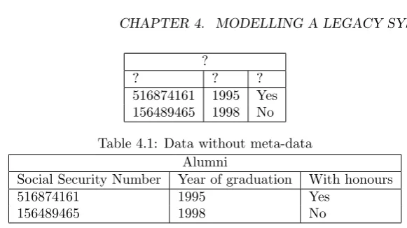
To store information, we generally encode it in data parts and meta-data parts. The meta-data defines the structure, and the data provides the instances of the structure. To retrieve the information, both the dataand the meta-data is needed. To illustrate this, take a look at table 4.1.
We can see part of the information, but we do not know what the data means. Therefore, unless we have the meta-data, it is completely useless. In table 4.2, the meta-data is added, and suddenly everything makes sense. The mysterious numbers from table 4.1 have now been given meaning. In the opposite case, where only the meta-data is known without the data, we also do not know
24 CHAPTER 4. MODELLING A LEGACY SYSTEM
?
? ? ?
[image:32.595.176.467.87.250.2]516874161 1995 Yes 156489465 1998 No
Table 4.1: Data without meta-data Alumni
Social Security Number Year of graduation With honours
516874161 1995 Yes
156489465 1998 No
Table 4.2: Data with meta-data
what the information is. The meta-data is only a structure, and until it is instantiated, we do not know the specifics. However, in this case, we do know somethingabout the data. If you look at table 4.2, and cover the lower (data) part of it, we do know that alumni are stored in this table. Furthermore, we know that theyhavea social security number, that thereisa date of graduation, and that the alumnus can be either graduatedwith honours ornot.
In general, we can define the parts of information in the data as ID and the
parts of information in the meta-data asIM. Theinstance of relationrbetween
the data parts and the corresponding meta-data parts is denoted as:
r:ID→IM
In the previous example, r would link the data part: 1995 to the meta-data part: Year of graduation.
With these definitions, we can also define the total amount of informationIas a combination of the parts of information in the dataID and in the meta-data
IM as:
I=ID./rIM
From this definition we can infer that in situations where the total amount of informationI remains equal:
• when the amount of information in the meta-data IM gets larger, the
amount of information in the dataIDgets smaller, and
• when the amount of information in the meta-data IM gets smaller, the
amount of information in the dataIDgets larger.
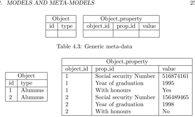
We shall illustrate the second statement with an example. The first statement can be inferred directly from this example as well. Consider the meta-data in table 4.3. This is an example of very generic meta-data. If we compare this to table 4.2, we see that the amount of information in the meta-data, or IM
4.2. MODELS AND META-MODELS 25
Object id type
[image:33.595.112.442.99.297.2]Object property object id prop id value
Table 4.3: Generic meta-data
Object id type 1 Alumnus 2 Alumnus
Object property
object id prop id value 1 Social security Number 516874161 1 Year of graduation 1995 1 With honours Yes 2 Social security Number 156489465 2 Year of graduation 1998 2 With honours No
Table 4.4: Generic meta-data with data
Compare the amount of tuples in table 4.4 and table 4.2. Not only are there 6 more tuples in the generic structure, the tuples also contain more information. The tuples in object property for instance, not only contain the value of the property, but also the type of property. In table 4.2, this kind of information was stored in the meta-data instead of in the data.
4.2
Models and meta-models
The relation between data and meta-data discussed in the previous section also applies to models and meta-models. A model is the data, and the meta-model is the meta-data. From the previous section we have seen, that this means we have a choice in how much information we put in a meta-model, and that this choice affects the amount of information in the model. Furthermore, the information that is stored in the meta-model is fixed, i.e. every model will have the same structure imposed by its meta-model. The information stored in the model is variable – this will change with each model.
The fact that the information in the meta-model is fixed, can be exploited by MDE tools for providing “model-generic” functionality. Consider, for example, a meta-model in which a relational data scheme can be modelled. When the meta-model exposes the fact that there are tables and columns and prescribes what properties these entities can have, we know that every model will use this structure to model relational schemes. This knowledgeabout the models, can be used to write code that generates DDL statements to create the actual tables in an RDBMS. This code is model generic, because it will work withany model that conforms to this meta-model. When the meta-model would only contain very generic constructs, like “objects”, and “properties of objects”, this would not be possible since an “object” can be anything.
26 CHAPTER 4. MODELLING A LEGACY SYSTEM
model-generic functionality. As a consequence, we see in the next chapter that the use of such a specific meta-model also imposes many constraints on the target model that need to be accounted for in the transformation. In the next section we examine if the meta-model for the source model should be generic or specific.
4.3
Generic or specific meta-model
Since we need to capture the information in the legacy system in a model, we need to decide what meta-model we should use. There are several approaches possible. Because there is a wide variety of legacy systems, we might be inclined to use a very generic meta-model – that is, a meta-model with little information about the system. That way, we have a lot of freedom in the model, because there are few restriction on what the model should look like. However, solely modelling the legacy system is not the only purpose here. We also need to be able to transform this model into a model which conforms to the meta-model of the MDE tool.
In chapter 3, we stated that a transformation model is created with the corre-spondences between the source meta-model and the target meta-model. This means that the meta-model that we choose for the source model has a great impact on the effectiveness of the transformation model. As we saw in the previous section, the use of model-generic functionality diminishes when the information in the meta-model gets smaller. In this case, model-generic func-tionality translates to transformation logic. This means that the use of a very generic meta-model – to generalize all legacy systems – would not work well in our approach, since we cannot define useful transformations on such a meta-model.
If, on the other hand, we make the source meta-model too specific, we run the risk that only few legacy systems can be modelled with it. In that case, we can define a good transformation model for it. However, since this meta-model – and consequently the transformation model – can only be used for a few specific legacy systems, this is not very model-generic either. So choosing the right meta-model is a trade-off between generalizing legacy systems and the ability to use useful model-generic functionality.
Our recommendation to modelling legacy systems would be to use specific meta-models which generalize a certain type of systems. Examples of types of sys-tems are: COBOL applications, Access applications, Lotus Notes applications, etcetera. In this way, we can use the meta-model for more than one legacy system while we also can employ model-generic functionality.
4.4
Knowledge Discovery Meta-model
4.5. CONCLUSION 27
Knowledge Discovery Meta-model, or KDM, is a standard meta-model for in-formation about existing software. Since it is a standard, it could be the case that there is already software available to create a KDM model from a specific legacy system. It would be a waste if that could not be used in our approach. While this meta-model contains many general and abstract constructs, it also contains possible specific instantiations of these abstract constructs. Using these more specific constructs it is possible to write model-generic code for the KDM. Therefore, our approach is, in principle, compatible with the KDM. However, there is also a downside in using the KDM for the source model. This concerns the fact that in order to fit the information from a legacy system in the KDM, an implicit model transformation occurs (from the legacy system into the KDM). This potentially causes a greater loss of information than when a custom, more specific, meta-model is used. This loss will not be detected with the automatic traceability, since that only traces the model transformation that occurs after this first step.
4.5
Conclusion
Chapter 5
Modelling model
transformations
In this chapter we focus on the second and third sub-questions. The second sub-question is: What is a tractable meta-model for modelling transformations from the source meta-model to the target meta-model? The third sub-question is: How can traceability be provided automatically? These sub-questions both concern the second step in the general approach, the model transformation. At this point, the legacy system is already represented by a model in the technical space of the MDE tool, but its meta-model is different from that of the tool. The result of the transformation should be a model that does conform to the meta-model of the tool. In this chapter we design a meta-model for model transformations, and show how automatic traceability can be provided.
In the next section, we first discuss the reasons for using a model for the trans-formation. After this, we discuss the various requirements on the transformation that need to be taken into account. We continue by reducing the model trans-formation problem to that of schema mapping in section 5.3. In the section thereafter, we discuss the cardinality of entities and the use of pre-processors. In section 5.5, we discuss two detailed examples of schema mappings, to make clear what needs to stored in the meta-model. After this, in section 5.6, we present the transformation meta-model. We conclude the chapter in section 5.7.
5.1
Why model the transformation?
To transform models, many transformation languages have been developed [23]. Instead of creating another transformation language, our approach is tomodel
the transformation and generate the transformation code from it. The benefits of modelling transformations over programming them (i.e. using a transforma-tion language) is that models are more synoptic and can therefore be created and maintained easier. And if the same MDE tool is used, modelling the trans-formation is not very different from modelling models that we already know: no
30 CHAPTER 5. MODELLING MODEL TRANSFORMATIONS
extra language needs to be learned to create transformations. Furthermore, if the MDE tool already has facilities for code generation, this can also be reused for the transformation model. Another benefit of using a model, is the fact that models are easy to analyse. We could, for example, analyse if a transformation contains conflicting rules. Since the MDE tools are already built to perform these kinds of analyses, it would be easy to provide this also for the transforma-tion model. With a new transformatransforma-tion language, this would be more difficult, since the transformation definition then needs to be parsed and interpreted first.
Transformation rules
It is common practice to divide a model transformation into smaller steps: trans-formation rules. This can be seen in many other approaches including ATL [13]. A transformation rule is a logical sub part of a complete transformation. A transformation rule specifies how a certain group of objects in the source model should be transformed into what objects in the target model. The whole transformation is comprised by the complete set of the transformation rules.
Between transformation rules there can exist dependencies. A dependency be-tween two transformation rules, means that the dependant rule can only be executed after the other rule is executed first. As such, the dependency causes an ordering to be formed in the execution of the transformation rules. Further-more, two transformation rules could conflict with each other, when they are mutually exclusive.
5.2
Requirements
From the research questions stated in chapter 1, we deduced several require-ments regarding the transformation and the transformation meta-model. These requirements are shown below:
• The transformation models should be executable
• The transformation meta-model is tractable
• Automatic traceability can be provided
• Custom analysis can be performed
The first and most important requirement is that a transformation model should
5.3. SCHEMA MAPPING 31
rather than on the (meta-)model of the transformation. It means, that when the transformation is executed, trace links are automatically created to link the source object with the target object and the corresponding transformation rule. The last requirement is that custom code can be used for more elaborate trans-formations that are not natively supported by the meta-model. An example of a more elaborate task would be the extraction of implicit constructs [14] in the source model.
5.3
Schema mapping
To make more clear what our goal is with a transformation model, we first look closer at the problem we need to solve. Our objective is to transform a model in such a way that it conforms to the target meta-model. This is quite an abstract definition, which makes it hard to specify the actions that need to be done to accomplish it. However, we can reduce this problem to a more specific one, that is arguably more comprehensible. In order to do this, we use the same correspondences between (meta-)data and (meta-)models as we have seen in chapter 4. This means that, a meta-model will translate into a relational data scheme, and a model will translate to the data in that scheme.
The objective to transform a model such that it conforms to the target meta-model, reduces then to transforming the sourcedatasuch that it fits in the target
scheme. In database research, this is accomplished with the use of schema map-ping. Because we represented models and meta-models by data and schemes, we now reduced the model transformation problem to a schema mapping problem. In the following, we therefore actually present a method for schema mapping. Just remember that this method is an implementation of the model transfor-mation in our general approach.
Schema elements
Schema mapping comes down to defining which elements of the target scheme correspond to (or can be found in) the source scheme. So what elements are there? The elements on which we focus from a relational data scheme are:
• Entities
– Tables with primary keys
• Attributes
– Columns
• Relations
– Foreign keys
32 CHAPTER 5. MODELLING MODEL TRANSFORMATIONS
entity. An example of a strong entity is a person, and an example of a weak entity is a marriage. A marriage is weak because it can only exist when the two persons that got married also exist. When mapping entities from the source scheme to the target scheme, we therefore need to start with a strong entity.
Attributes contain the values that belong to an entity. In a relational database, an attribute is represented by a column. An attribute can only be mapped when the entity that it belongs to is already mapped. So, the attribute mapping depends on its entity mapping.
Relations in this context are connections between entities (instead of entities themselves). A relation between two entities is represented in a relational database by a foreign key constraint. Relations play a major role in our schema mapping approach, because they contain much information about the overall structure of a scheme.
5.4
Cardinality
We identify two important requirements on a mapping between two entities. The first is that the two entities must correspond to each other semantically. This means that they represent the same, or a similar concept in both systems. The second requirement constricts this further, by requiring that the entities have the same cardinality. This means that the number of occurrences of the concept in the source system is equal to the number of occurrences of the corresponding concept in the target system, i.e. they relate one to one. Our transformation meta-model can only map entities that conform to these requirements. If the cardinality is different between two similar entities, the source scheme needs to be pre-processed to enable the use of the transformation model. The cardinality between two entities can be different if, for instance, the source system has a denormalized entity, which is normalized in the target system. To solve the issue, we need to apply a grouping operation on the denormalized entity, and store the result in a new entity. The new entity can then be mapped to the entity in the target scheme. The grouping operation is what we call a “pre-processor”, and this is discussed further in the next subsection.
Pre-processors
In order to keep the transformation meta-model tractable, we opted for the use of custom pre-processors in cases where one to one mappings do not suffice. Having a simple transformation model makes it easier to create it, analyse it and process it. We expect that in most cases the transformation model would be sufficient. Only when “heavy lifting” like grouping, splitting, or even data-mining needs be performed, a pre-processor is needed. In this way, the transformation model stays relatively clean, and the pre-processors can tackle the more complex issues.
5.4. CARDINALITY 33
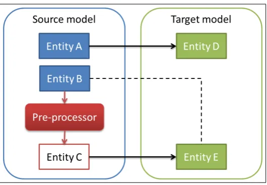
Figure 5.1: A schematic example of entity mappings where a pre-processor is used for entity B.
in the source model and entity E in the target model means that these entities are also similar. In this case, however, the entities cannot be mapped directly. This can have several reasons. The entities could, for instance, not have the same cardinality, i.e. they do not correspond one-to-one. Another possibility is that the information in entity B requires some complex analysis, like parsing or data mining, to extract the relevant parts. Therefore, instead of directly mapping entity B to entity E, the source model is extended with an extra entity: entity C, which is the result of a pre-processor for entity B. This new entity C does have the same cardinality of entity E, and can therefore be mapped to entity E.
A pre-processor can be seen as a custom function that takes an entity from the source scheme as input and produces output in a new entity in the source scheme. The output is then used in the transformation model. Therefore, the pre-processor is also part of the transformation, which means that trace links need to be created for its actions. Since the pre-processor contains custom code, this is not trivial.
However, when a pre-processor can do its work with only one tuple at the time, a framework can be constructed in which the pre-processor is called for each tuple in the input entity. The framework then always knows what the current input tuple is, and also receives what the pre-processor outputs. The framework is then able to create the appropriate trace links for the pre-processor. The trace links that are created for a pre-processor consist of a combination of the input tuple, the output tuple, and an identifier for the pre-processor. The input and output entity of a pre-processor always reside in the source model. A framework like this is also used in chapter 7.
34 CHAPTER 5. MODELLING MODEL TRANSFORMATIONS
also supports set-based pre-processors.
Since both the input and output entity of a pre-processor reside in the source model, it is also possible to “chain” multiple pre-processors. The output entity of one pre-processor is then used as the input entity in the next pre-processor. The output of this second pre-processor can, in turn, be the input for a third pre-processor, and so on. It is obvious that the execution of these pre-processors requires an ordering. The ordering is determined by the chain; a pre-processor can only be executed when its input entity is not an output entity of another pre-processor, or when this other pre-processor is already executed. The trace links for these pre-processors also form a chain. Furthermore, the trace links are transitive, such that: a→ b→ c results in: a→c, wherea, b, c ∈T uples
and→denotes a trace link.
5.5
Example mappings
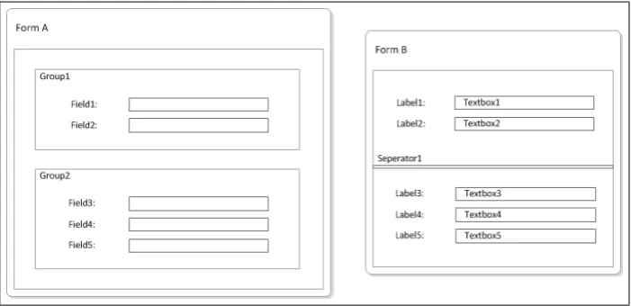
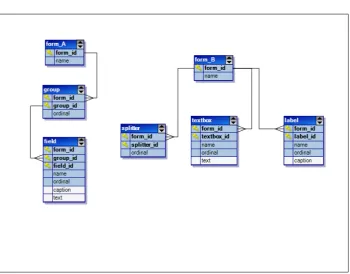
[image:42.595.151.502.523.693.2]Before we present the transformation meta-model, let us first consider two exam-ples of the kinds of transformation models (mappings) that need to be supported by it. This will help in clarifying the problems and the design decisions for the meta-model. The examples are based on two different meta-models (A and B) for modelling forms in a GUI. In figure 5.2, the different forms are shown that can be modelled with these meta-models and in figure 5.3, the meta-models are shown as ERD’s. We can regard meta-model A as the legacy meta-model and meta-model B as the MDE meta-model, or vice versa. As can be seen from the figures, meta-model A structures the elements on a form in groups, whereas in meta-model B, a splitter is used to separate the elements. In the ERD’s, we can recognize this by the hierarchical structure of meta-model A, and the more flat structure of meta-model B. Furthermore, the controls on the two forms are also slightly different. Meta-model B useslabels andtextboxes, but meta-model A only usesfields, which are a composite of these.
5.5. EXAMPLE MAPPINGS 35
Figure 5.3: Forms example
The first example that we discuss is a transformation from meta-model A to meta-model B. In this situation, meta-model A acts as the legacy meta-model and meta-model B acts as the MDE meta-model. After this, we discuss a second example of the opposite transformation, from meta-model B to meta-model A. As we know from section 3.2, the transformation model is positioned at the level of the meta-models of the source and the target model. This means that the transformation model maps the constructs in the source meta-model to the constructs in the target meta-model. In our case, these “constructs” are the entities, relations and attributes shown in figure 5.3. Recall that by defining the mappings on this (meta) level, the transformation model can be reused for every instance (read: model) of the source meta-model.
5.5.1
From meta-model A to meta-model B
36 CHAPTER 5. MODELLING MODEL TRANSFORMATIONS
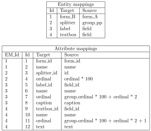
Entity mappings Id Target Source 1 form B form A 2 splitter group pp 3 label field 4 textbox field
Attribute mappings EM Id Id Target Source
1 1 form id form id 1 2 name name 2 3 splitter id id
2 4 ordinal ordinal * 100 3 5 label id field id 3 6 name name
3 7 ordinal group.ordinal * 100 + ordinal * 2 3 8 caption caption
4 9 textbox id field id 4 10 name name
[image:44.595.170.474.122.384.2]4 11 ordinal group.ordinal * 100 + ordinal * 2 + 1 4 12 text text
Table 5.1: Example mapping A to B
Let us first consider the entity mappings. The form_A and form_B entities are mapped directly, as well as the field and label entities. However, the
fieldentity is mapped also to the textboxentity. Although thegroupentity from meta-model A and the splitterentity from meta-model B have similar semantics – they both separate groups of elements on a form from each other – we cannot map these directly. This is because the cardinality is different here: there is always one more group than there are splitters. Furthermore, in meta-model A, there is always at least one group in every form, but in meta-meta-model B, a form can exists without a splitter. To take care of this, a pre-processor for the group entity is used. This pre-processor creates a new entity in the source meta-model: group_pp. For each group in a form, except for the first, the pre-processor creates agroup_pptuple. In thegroup_pptuple, theordinal
column is copied from the group tuple. In this way, the group_ppentity and thesplitterentity, do have the same cardinality. Subsequently, thegroup_pp
entity (instead of thegroupentity) is mapped to the splitterentity.
From the attribute mappings, we can see that most attributes are mapped directly, but there are some exceptions regarding the ordinal numbers. In order to maintain the same grouping of elements on the form, the ordinal numbers of the elements cannot be copied directly from the source model. This is because, in the source model, the ordinal numbers are always in the context of agroup
5.5. EXAMPLE MAPPINGS 37
ordinal by 100, and add this as a premium to the ordinals of the elements. This allows for 100 elements per group. Furthermore, since a field is split up into a label and a textbox, the ordinal of a field is multiplied by 2. And since a label usually precedes the textbox, we added zero to the label ordinal and 1 to the textbox ordinal.
The mappings above are clean and simple, because they rely on some important assumptions. The first assumption is that the value for theform_idattribute in the target model only has to be determined at the mapping fromform_Ato
form_B. In thesplitter, label and textbox entities, the value forform_id
should be found by utilizing the relation toform_B. Furthermore, the calculation of the ordinal number for thelabel andtextboxentities employs a lookup to thegroup table in the source model. Recall that these entities are mapped to thefieldentity, and not to thegroup entity. The assumption is that, during execution, thegroupentity can be joined to perform this lookup. The relation between thegr

![Figure 2.1: The four layered architecture of the Meta Object Facility (from [12])](https://thumb-us.123doks.com/thumbv2/123dok_us/1192582.642507/19.595.101.452.117.410/figure-layered-architecture-meta-object-facility.webp)