Complex Systems Informatics and Modeling Quarterly
CSIMQ, Article 70, Issue 12, September/October 2017, Pages 39–65 Published online by RTU Press, https://csimq-journals.rtu.lv
https://doi.org/10.7250/csimq.2017-12.03 ISSN: 2255-9922 online
A Quality-Driven Methodology for Information Systems Integration
Iyad Zikra*, Janis Stirna* and Jelena Zdravkovic*
Department of Computer and Systems Sciences, Stockholm University, Box 7003, Kista, 16407, Sweden
[email protected], [email protected], [email protected]
Abstract. Information systems integration is an essential instrument for organizations to attain advantage in today’s growing and fast changing business and technology landscapes. Integration solutions generate added value by combining the functionality and services of heterogeneous and diverse systems. Existing integration environments tend to rely heavily on technical, platform-dependent skills. Consequently, the solutions that they enable are not optimally aligned with the envisioned business goals of the organization. Furthermore, the gap between the goals and the solutions complicates the task of evaluating the quality of integration solutions. To address these challenges, we propose a quality-driven, model-driven methodology for designing and developing integration solutions. The methodology spans organizational and systems design details, providing a holistic view of the integration solution and its underlying business goals. A multi-view meta-model provides the basis for the integration design. Quality factors that affect various aspects of the integration solution guide and inform the progress of the methodology. An example business case is presented to demonstrate the application of the methodology.
Keywords: Systems Integration, Integration Quality, Integration Methodology, Enterprise Modeling, Model-Driven Development, Interoperability.
1
Introduction
The contemporary business environments are characterized by fast change and considerable unpredictability which pushes organizations to seek dynamic and adaptive solutions to preserve the advantage against competitors and to protect and expand the customer base (e.g. by offering personalized products or services). New and novel technologies are appearing at an ever-quicker pace, further contributing to the increased significance of acquiring solutions that are dynamic and adaptive. Much of the solutions that are needed cannot be delivered by the more established principle of developing software applications from the ground up. Instead, the solutions that meet the contemporary demands of adaptability and configurability should be integration
*
Corresponding authors
© 2017 Iyad Zikra et al. This is an open access article licensed under the Creative Commons Attribution License (http://creativecommons.org/licenses/by/4.0).
Reference: I. Zikra, J. Stirna and J. Zdravkovic, “A Quality-Driven Methodology for Information Systems Integration,” Complex Systems Informatics and Modeling Quarterly, CSIMQ, Issue no. 12, pp. 39–65, 2017. Available: https://doi.org/10.7250/csimq.2017-12.03
orcid.org/0000-0002-3669-solutions, i.e. they should be built by the means of integrating existing systems and components. Integration solutions provide added value to the organization by automating the communication between, and combining the functionality of, two or more information systems (IS).
The importance of IS integration for the success of organizations is emphasized by its widespread utilization in the business world. Yet, IS integration remains vaguely defined as a research area, e.g. lacking a common language for effective communication which would be essential for developing a community with shared values [1]. An IS integration community can facilitate the exchange of ideas across otherwise unrelated domains, which can ultimately lead to better research and actual improvements in business-IT alignment—which is consistently viewed as the top management concern [2].
IS integration is viewed as a multidisciplinary domain that includes diverse organizational and system design topics alongside technology-oriented topics. The theoretical foundations of IS integration are dispersed across many IS domains, ranging from the very technical (e.g. process execution and middleware) to the management-oriented (e.g. strategic management and organization theory), and covering everything in between (e.g. schema integration, business process modeling, enterprise modeling). Furthermore, integration solution development is traditionally dependent on the commercial platform chosen for the implementation of the IS. Different platforms impose different technical requirements and constraints, which often cause the solution to drift away from the original business goals for which it is being developed.
The diversity of integration-related topics complicates the task of aligning the organizational business goals, including those related to integration, and the implementation of the integration solution. It is common for organizations to resort to ad-hoc means to maintain the alignment, i.e. without relying on any systematic approach for the transition from management-level integration design to technical-level integration design. Viewed from an organizational perspective, alignment can be stated as the quality of the integration solution, expressed by its added value. I.e., an IS integration solution with high quality is one that is well aligned with the organizational goals. Studying the quality of IS integration is also hampered by the heterogeneity of integrated systems, integration techniques, and the fact that research on integration is dispersed in diverse fields.
This article proposes a quality-driven and model-driven methodology for designing and developing IS integration solutions. The methodology is tailored to account for the requirements of IS integration. It supports continuously monitoring the solution’s quality during the design and development process. It utilizes the principles of Model-Driven Development (MDD) to bridge the gap between organizational and IS design knowledge. Formal meta-models are used to capture the integration design and relate it back to the underlying business integration goals. Furthermore, the stages of the methodology are guided by quality factors that affect different elements of the design and development process. The quality factors are elicited from various IS domains and reflect the diversity associated with IS integration. The proposed methodology contributes to better alignment between the developed integration solution and the business goals of the organization. It also contributes to the development of robust solutions by using formal models and transformations to describe and derive the solution implementation. Furthermore, by continuously assessing the quality factors, the methodology guarantees the implementation of an integration solution with measurable added value.
2
Research Approach
The main activity of IS research has long been recognized as that of designing and developing artifacts, i.e. the design artifacts, that solve real world problems [3], [4]. The development of organizational artifacts is a common practice in European IS research communities [1]. The research presented in this article describes the development of one such organizational artifact: a quality-driven and model-driven IS integration methodology. The artifact is developed following the six stages of Design Science Research Methodology (DSRM) [5]. This section describes how the stages were followed during the course of this research.
The first stage of DSRM identifies four possible entry points to IS research. During this stage, the research problem is identified and motivated, and its relevance to the application environment (i.e. business world) is established. This article adopts the problem-centered entry point to the research. Section 3 explores current research on IS integration methodologies and identifies a gap between the organizational design and technical design of integration solutions. The background investigation also reveals the inadequacy of existing approaches for maintaining the quality of integration solutions. These observations are reinforced by the authors’ own experiences as both IS integration developers and teachers of IS integration courses.
The second DSRM stage describes the formulation of the research objectives. In this article, the objectives are: 1) to improve alignment between the organizational and technical aspects of IS integration solutions, and to 2) maintain the quality of the integration solutions throughout the design and development process. In other words, the design artifact is intended to bridge the gap between the organizational and technical designs while offering support for describing, evaluating, and improving the quality of the integration solution.
The actual creation of the design artifact is the third stage of DSRM. The desired artifact needs to offer holistic guidelines for designing and developing integration solutions, i.e. an IS development methodology. It is a methodology for designing and developing IS integration solutions. In particular, it needs to support the transition from the organizational design to the technical design. To achieve this connection, the methodology relies on the principles of MDD for capturing the design details on both levels (organizational and technological) and transforming the models of the integration solutions into an implementation in a specific integration environment. Finally, the design artifact needs to support the process for describing and evaluating quality throughout the design and development process, which is in contrast to other approaches that suggest evaluating the quality of the integration solution after its completion. The details of the proposed integration design methodology went through several iterations of the design cycle, as dictated by the principles of DSRM. The final methodological guidelines are presented in Section 5.
The fourth DSRM stage emphasizes the importance of demonstrating the applicability of the proposed artifact. To this end, an example business case is presented in Section 6. A prototype tool that has been developed to support the methodology is used to develop integration design models, both organizational and technical. The models capture, among other things, the quality aspects of the design, and the example case illustrates how the methodology supports the process of evaluating and improving the solution’s quality throughout design and development.
The fifth stage of DSRM describes the evaluation of the developed artifact. This stage provides additional support to the viability of the proposed artifact as a solution to the identified research problem. In this article demonstration serves the role of evaluation by offering an example instantiation and application of the artifact [5]. Such approach is applicable in validation, especially when repeatedly applying the artifact and measuring its influence is practically difficult, which is a common problem to all IS research [1]. Further evaluation of the methodology is planned in future research
3
Background on Information Systems Integration
This section provides the necessary theoretical foundation for scoping the contribution of the article. It starts by identifying and contrasting the ways in which IS integration is approached in the research literature. It continues by focusing on how quality is viewed within the scope of IS integration. Finally, it summarizes the major methodologies for developing integration solutions.
3.1 Information Systems Integration
IS integration emerged from the domains of Enterprise Resource Planning (ERP) and Enterprise Application Integration (EAI) [2], [6]. Since the turn of the 21st century, it has been consistently ranked amongst the top application and technology areas in terms of importance for investment [2]. However, the term grew to embody areas that are usually considered distinct as far as IT management is concerned [7], [8]. It currently describes the combination of technologies and patterns that are used to realize organization-wide integration of heterogeneous information and processes [7]. Integration projects commonly include elements from such diverse, loosely-related domains as distributed systems, databases, enterprise architecture, middleware, Service Oriented Architecture (SOA), Business Process Management (BPM), and cloud computing. Several of the domains are themselves top ranking application and technology investment areas [2]; which indicates that in practice the importance of systems integration is even higher.
In addition to the technological perspective, IS integration is studied within the fields of strategic management and organization theory [9], where it is part of the wider organizational integration. Organizations rely on integration to grow, whether through acquisitions and mergers [10], [11] or to support strategic partnerships or operational necessities [12]. Growth objectives indirectly drive IS integration through deciding the type of organization that will emerge from the integration [10]. Analysis of the existing architectures and the degree of IS standardization can help in selecting a strategy for total, partial, or no IS integration to accompany organizational integration [10]. IS integration can be a part of horizontal integration (i.e. spanning multiple organizational units) or vertical integration (i.e. spanning several layers within an organizational unit) [8]. It can also be a part of internal integration (i.e. within a single organization) or external integration (i.e. connecting partners in pooled, sequential, or reciprocal interdependencies) [9]. Furthermore, the success of IS integration is heavily affected by business and organizational factors [13], and is influenced by contextual business variables, including the types, sizes, and geographical locations of the businesses being integrated [10].
Despite its role in creating added value, the complexity associated with IS integration has led to limited research around the concept itself [7]. Studying IS integration is fragmented and usually focuses only on one component of integration. Some organizations even decide to skip IS integrating altogether during mergers, often because the technological perspective is overlooked [11]. Top IT management concerns include business-IT alignment, enterprise architecture, and change management, among others [2]. Yet, IS integration is not viewed as a top concern, despite its close relationship to the other members of the list.
3.2 Quality in Systems Integration
identify the dimensions along which integration can be described [7], [8], [15]. The dimensions include integration domain (data vs. process), integration time (ex-ante vs. ex-post), integration type (vertical vs. horizontal; alignment vs. merging), and integration level (strategic vs. systems). Integration is affected by the organizational objectives and antecedent contextual variables. The development of a theoretical framework for integration is hampered by the fragmentation of integration related concepts along the dimensions [15].
The main concern in data integration problems is usually conflict resolution amongst the sources to guarantee consistency [16]. Quality can be managed on the query level, where queries are modified to select data that fulfills certain quality thresholds. Alternatively, other data quality management techniques rely on schema integration or instance-level conflict resolution [17].
Process integration through adapters is a popular approach [18]. Adapters mediate the interaction between the integrated systems. Characteristics of the adapters (e.g. configuration complexity and Quality of Service (QoS) attributes) can be viewed as quality factors. They aid in choosing suitable adapters that fulfill certain integration needs. Once deployed, an integration process can enter the execution phase following a triggering event. The execution of a process leaves a trace called a process log. Analyzing the log can help in improving the quality of the process, e.g. in regards to efficiency, timeliness, and so forth [19], [20].
Integration quality can be managed as part of the architectural design. For example, a model to support architectural design decisions in integration is proposed in [21]. The model describes the relationship between integration design objectives, technology capabilities of the systems being considered for integration, and the capability evaluations. The model views IS capabilities as qualities that affect the decision for selection or rejection. Another example is the work in [22], which describes an integration architecture that manages the quality of data exchanged between the systems. The architecture includes a broker responsible for runtime selection of data from a specific system based on quality assessments.
3.3 Methodologies of Systems Integration
Established IS development methods, whether plan-driven or agile, lack the necessary structures to handle the organizational and technical requirements specifically associated with integration projects [23]. Many integration projects are assigned as business process reengineering projects, in which integration requirements are realized through existing or new information systems [24]. Research on IS integration methodologies focuses mainly on the organizational aspects [10]; i.e., it covers the stages that precede the actual solution development. In practice, the details of developing integration solutions are tightly coupled to the technologies offered by commercial tools.
Nevertheless, some methodologies exist to specifically target the needs of IS integration. According to [24], a methodology for IS integration should cover the initial stages of planning and simulation to evaluate the needs and costs of the project. It should simultaneously cover the actual development and testing stages of the integration solution.
The methodology in [23] emphasizes the importance of understanding the end-to-end business process ahead of integration. This is to avoid overloading the integration design with technology-specific details. The methodology proceeds to map the processes onto components in a centralized integration architecture.
The work in [10] proposes a decision support model for selecting a suitable integration strategy. The model relies on evaluating variables that describe the organizational and integration contexts. The variables are structured hierarchically in terms of importance and abstraction level. Once a strategy is chosen, the details of the integration solution can be outlined.
and compare the improvements introduced by alternative, simulated integration scenarios. It thereby aids in deciding whether integration is a suitable solution for a given problem. However, it overlooks the organizational and technical details of developing the integration solution.
The waterfall development lifecycle is adapted in [26] to become a methodology for supply chain integration. The methodology includes two phases: a reverse engineering phase to describe the current and future states using models, and a forward engineering phase to implement the future state and realize integration needs. Goals and quality are partially captured in the models among other details of the organizational design. However, the methodology is not model driven. A generic process model for IS integration activities is presented in [27]. The process model can be used in relation to organizational acquisitions and mergers. It supports three types of integration strategies: IS absorption, IS co-existence, and IS renewal. The methodology developed in [4] relies on models of the integration solution to improve alignment between the organizational design and the technical details of the solution. The integration architecture is organized in three views: business processes view, data view, and organizational role view. The methodology is communication oriented, i.e. it follows a paradigm that enables describing the interaction between systems as well as improves business-IT alignment [28].
Some integration methodologies offer partial support for maintaining the quality of integration solutions. The proposal in [29] relies on system quality factors, including understandability, timeliness, and consistency, to evaluate and rank candidate systems as data sources for integration. The work in [17] proposes a methodology for quality-based data integration. It relies on an ontology to evaluate the data sources and guide the creation of a global integration schema. The methodology is implemented in a supporting tool. The work in [30] proposes using enterprise modeling to evaluate the quality of integration solutions. It identifies evaluation requirements and uses models to capture the integration effects based on the type (coupling vs. merging) and range (internal vs. external) of integration and along multiple organizational views. When it comes to IS architecture, methodologies have been proposed to aid in the selection of appropriate design decisions. Such methodologies are not specifically designed to support integration. However, IS architecture is an important component of integration. Architectural design decisions tend to be driven by technological requirements and constraints [21], which also emphasizes the effect of technology on business-IT alignment. A process for integration architecture design is proposed in [31]. It relies on a model that captures the relationships between systems, their desired properties and qualities, and the design decisions. The model is thereby able to explicitly capture the motivation behind the architectural design decisions. It is used to compare and select amongst different integration strategies and designs.
4
Quality Factors for Integration Design
A holistic view of IS integration quality must account for the diversity of the IS domains that affect integration design. As discussed in the previous section, IS integration is a multidisciplinary area that covers activities from a variety of domains. Section 3.2 explored the research works that address quality in these domains, including the quality of data, systems, models, and processes. However, research is limited when it comes to the impact of quality on the overall integration design [32]. The authors of this article have developed a quality framework that provides the needed holistic view of IS integration quality. The framework combines quality factors that are relevant to IS integration as described in the related IS domains. A summary of the framework is presented in this section. A more detailed description can be found in [33].
1. Factors that affect the candidate systems for integration, including such factors as reliability, compatibility, price, and integrity.
2. Factors that pertain to the use of models for capturing the integration design, including factors such as understandability, completeness, and interpretation.
3. Factors that cover the integration design process. The integration methodology presented in this article represents the realization of this category.
4. Factors that cover the quality of the created integration solution. It aptly includes quality factors that are abstract and business-oriented. A suitable quality framework (e.g. [34]) is required to evaluate these factors, with the help of factors in the other categories.
5
Quality-driven Methodology for Integration Design
In this section, we propose a quality-driven and model-driven methodology to address the quality and alignment problems that influence IS integration. In contrast with the works discussed in Section 3.3, our proposed methodology spans all stages of design and development of IS integration solutions. The modeling foundation for capturing the integration design is the Unifying Meta-Model (UMM) proposed in [35]. The methodology extends the ability of the UMM. Furthermore, the methodology is driven by the quality factors proposed in [33] and summarized in Section 4.
The UMM enables describing enterprise and IS design knowledge in a holistic manner. It offers complimentary views that cover organizational goals (Goals View, GV), concepts (Concepts View, CV), business processes (Business Process View, BPV), and IS architecture (Information Systems Architecture View, ISAV). Each view defines the necessary modeling components to capture that specific perspective of the enterprise or the supporting IS. The ability of the UMM to describe the integration of cloud-based services [36] and the communicative nature of IS integration [37] is developed further in this article. The Quality View (QV) extends the UMM to enable modeling quality factors and associating them with other components of the integration design models. The Mapping View (MapV) and Transformation View (TV) extend the UMM to support describing the generation of the integration solution from the integration design.
The methodology relies on the unifying meta-model because, in addition to its ability to capture the organization using different complementary views, it is able to capture the quality factors associated with the modeling components, with the help of the Quality View (QV).
The IDEF0 modeling notation [38] is used to illustrate the methodology. IDEF0 offers the necessary modeling components for describing methodologies for systems development [39], albeit in a simple and effective manner.
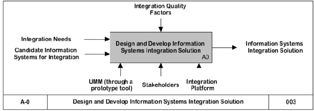
In terms of the IDEF0 notation, a box represents an activity. Inputs and outputs to the activity are described using arrows that enter the box from the left side and exit from the right side, respectively. Arrows that enter the box from the top describe control information that affects how the activity is performed. Arrows that enter the box from the bottom describe the mechanisms that are necessary to perform the activity. Arrows can merge and split to denote, e.g. a composite piece of information or a manifold control. The hierarchical structure of IDEF0 activities can be described by exposing the internal details of the activity using another model at a lower level of abstraction, denoted by the activity ID. The label at the bottom center and bottom left corner of an IDEF0 model are the title and ID of the activity described by the model. The label at the bottom right corner is the revision number.
necessary formalism to associate the steps prescribed by the methodology with the expected outcome, the required inputs, the underlying intentions, and the reuse context [41].
The use of IDEF0 and method chunks enables the systematic exploration and analysis of the methodological guidelines. Consequently, the quality of the integration design methodology is improved, contributing to the fulfillment of the integration design process quality factors.
The UMM views that are used in the methodology are illustrated in the relevant method chunks below. Concepts in the UMM are graphically represented as yellow boxes. Relationships between the concepts are represented as concepts as well to highlight their role in unifying the organizational and system design knowledge. Red boxes describe intra-model relationships between concepts within a single view. Blue boxes describe inter-model relationships (IMRs), i.e. relationships across views. The IMRs facilitate inherent traceability between the views on the meta-modeling level, thus enabling integrated tooling support. Boxes that include an arrow in the top-right corner indicate that the modeling component is defined in another view.
Figure 1 presents the entire methodology as a single activity at level A-0 (pronounced “A minus zero”) in IDEF0, which is the top-most level. Two inputs to the methodology are identified. The first is the integration needs, broadly defined within the context of organizational integration. The methodology assumes that the need for an IS integration solution is already established. The integration needs will be structured as a goal model during the first stage of the methodology. The second input to the methodology is a list of candidate information systems for integration. Management decisions may dictate the inclusion of certain systems, whether legacy or newly developed (e.g. to adapt a novel technology or cater to emergent requirements).
The output of the methodology is an IS integration solution. In the proposed methodology, Microsoft BizTalk Server [42] is the selected integration platform to implement the solution. However, other platforms can be used, and the guidelines presented in Section 5.3 can be adapted accordingly.
Integration quality factors (Section 4) constitute control information that drives the execution of the methodology. At the top-most level, it is sufficient to represent all the factors as a single control. The details of the stages will reveal how the different types of quality factors affect different parts of the methodology.
Figure 1. Overview of the integration design methodology
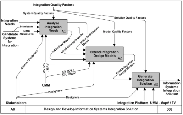
The methodology is divided into three main stages, illustrated as the details of activity A0 in Figure 2. The stages are related to each other with the help of inputs and outputs. The controls and mechanisms that were identified at level A-0 are refined to show how they influence each stage. In the following sections, each stage is decomposed into smaller activities, and activities at the lowest level of detail are described using method chunks
Figure 2. The main stages of the integration design methodology
5.1 Stage 1: Analyzing the Integration Needs and Deriving Initial Models
The first stage of the methodology, i.e. activity A1, covers the formalization of integration goals and the identification of suitable systems for integration. Figure 3 illustrates the first stage, and the details of the sub-activities are described using method chunks. The definitions of method chunks are presented in Tables 1–4.
Table 1. Definition of method chunk A1.1
Chunk ID: A1.1 Name: Design Integration Goal Model Type: Atomic
Objective: Identify and describe the business-level integration goals. Reuse situation: Human.Designer
Human.Analyst
Application Domain.Application Type.Intra-Organization Application
Application Domain.Application Type.Inter-Organization Application
System Engineering Activity.Enterprise Modeling
System Engineering Activity.Requirements Engineering.GORE
System Engineering Activity.Model-Driven Development.Modeling
Reuse intention: Structure and formally represent the underlying motivation for developing an integration solution. Interface:
Situation: Textual descriptions of integration needs (through documentation, interviews, etc.). Body:
Product: Initial goal model, an instance of the Goals View of the UMM
Guideline:
The textual descriptions of the integration needs are studied and the intentional components that underlie the integration project are identified.
Problems are identified and associated with the Causes that Explain them. Problems can be internal (i.e. Weaknesses), external (i.e. Threats), or operational (i.e. Constraints).
Business Goals that address and are Hindered by the problems are identified.
Opportunities are potential business goals. However, they lack the clarity and concrete details that characterize goals.
Intentional components, specifically goals and opportunities, express Support relationships.
Goals can be decomposed into smaller, more refined goals using the Refinement relationship.
In integration contexts, Roles describe the systems that perform activities in the integration chain. Therefore, the ResponsibleFor relationship will be utilized while designing the integration architecture.
Business goals motivate other parts of the integration design, as described using the remaining views of the UMM. The Motivate relationship will be utilized at later stages in the methodology.
Application example: See Section 6.
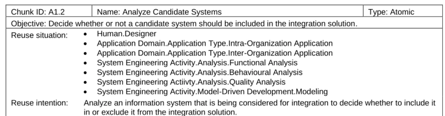
Table 2. Definition of method chunk A1.2
Chunk ID: A1.2 Name: Analyze Candidate Systems Type: Atomic
Objective: Decide whether or not a candidate system should be included in the integration solution. Reuse situation: Human.Designer
Application Domain.Application Type.Intra-Organization Application
Application Domain.Application Type.Inter-Organization Application
System Engineering Activity.Analysis.Functional Analysis
System Engineering Activity.Analysis.Behavioural Analysis
System Engineering Actiivty.Analysis.Quality Analysis
System Engineering Activity.Model-Driven Development.Modeling
Interface:
Situation: Initial goal model
Interface details of the candidate system
Data structure of the input (required) and output (provided) of the candidate systems Body:
Product: An updated version of the initial goal model, showing the systems which are responsible for fulfilling the goals
Initial integration architecture model, an instance of the Information Systems Architecture View of the UMM
Initial quality model, an instance of the Quality View of the UMM.
Data structures of the input (required) and output (provided) of the accepted systems Guideline: For each candidate system:
Define a System in the integration architecture model. Identify the Platforms to which the system belongs and the InterfaceTypes that the system exposes. (Notes: a platform can be an operating system (e.g. Windows, Linux), a development framework (e.g. J2EE, .Net), a programming language (e.g. C#, Python), or a product family (e.g. SAP, Apache). It is possible for a system to belong to several
platforms). Interface captures the specific details of the system’s interface when available. A system may CommunicateVia several interfaces.
Identify the integration business goals (from the goal model) that the system can help fulfill. Associate the goals to the system by assigning the Role of the system using the CorrespondsTo relationship.
Assign the applicable SystemQualityFactors that Describe the system. The factors may be selected from a preexisting list, or custom-created for the project, as discussed in [33]. Assign each factor to the BusinessGoals that Characterize it, i.e. motivate the selection of the factor and show which business goals are affected by it.
Assign acceptanceThresholds to the factors. The thresholds help in choosing the systems that possess acceptable quality levels.
Calculate a Measurement for each of the quality factors. The values of the factors are relative to other candidate systems and help in selecting the systems that best fit the integration needs (especially in cases where several systems can fulfill the same business goal). Some quality factors may have ordered values (e.g. numerical values for Freshness and Price, or discrete values for Reliability (low, medium, high)). Other factors may have qualitative values (e.g. Compatibility) and can be calculated with the help of Platform and InterfaceType. E.g., the designer may prefer a certain system because it belongs to the same platform as other already chosen systems. Furthermore, specific quality frameworks can be applied to calculate the factor.
If there are unfulfilled goals in the goal model at the end of this activity, then proceed to activity A1.3. The data structures from accepted systems provide input to activity A1.4.
Table 3. Definition of method chunk A1.3
Chunk ID: A1.3 Name: Identify New Candidate Systems Type: Atomic
Objective: Find a candidate system that is able to fulfill all or part of the integration needs. Reuse situation: Human.Designer
Human.Analyst
Application Domain.Application Type.Intra-Organization Application
Application Domain.Application Type.Inter-Organization Application
Application Domain.Legacy System.Interface Reuse
Application Domain.Legacy System.Functional Domain Reuse
Reuse intention: Based on integration needs, find an information system that has the potential to provide part or all of the required data/functionality.
Interface:
Situation: Outstanding integration needs, described as goals in the initial goal model that lack ResponsibleFor relationships to any systems
Body:
Product: New candidate systems for integration, including:
Interface details of the candidate system
Data structure of the input (required) and output (provided) of the candidate system
Guideline: This is a creative activity to uncover suitable information systems that are able to fulfill the modeled integration goals. Once a system is identified, it is passed to activity A1.2 for systematic scrutiny and suitability analysis.
Application example: See Section 6.
Table 4. Definition of method chunk A1.4
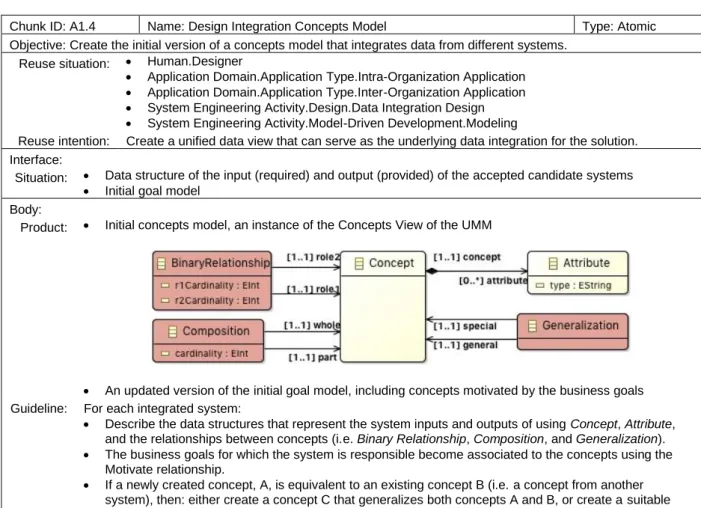
Chunk ID: A1.4 Name: Design Integration Concepts Model Type: Atomic
Objective: Create the initial version of a concepts model that integrates data from different systems. Reuse situation: Human.Designer
Application Domain.Application Type.Intra-Organization Application
Application Domain.Application Type.Inter-Organization Application
System Engineering Activity.Design.Data Integration Design
System Engineering Activity.Model-Driven Development.Modeling
Reuse intention: Create a unified data view that can serve as the underlying data integration for the solution. Interface:
Situation: Data structure of the input (required) and output (provided) of the accepted candidate systems
Initial goal model Body:
Product: Initial concepts model, an instance of the Concepts View of the UMM
An updated version of the initial goal model, including concepts motivated by the business goals Guideline: For each integrated system:
Describe the data structures that represent the system inputs and outputs of using Concept, Attribute, and the relationships between concepts (i.e. Binary Relationship, Composition, and Generalization).
The business goals for which the system is responsible become associated to the concepts using the Motivate relationship.
If a newly created concept, A, is equivalent to an existing concept B (i.e. a concept from another system), then: either create a concept C that generalizes both concepts A and B, or create a suitable binary relationship between concepts A and B.
5.2 Stage 2: Extending and Evolving the Integration Design Models
Initial models of the integration goals, concepts, and architecture represent the inputs to the second stage (i.e. activity A2) of the methodology. During this stage, the models are reviewed and complemented with the information necessary to realize the integration solution and fulfill the integration goals. The integration process model is created to describe the information flow between the integrated systems. The evolution of the models is guided by the model quality factors that were discussed in Section 4. Figure 4 illustrates the sub-activities of activity A2. Each sub-activity is described as a separate method chunk (see Tables 5–7).
Figure 4. Details of the second stage of the methodology. Level A2 of the IDEF0 notation
Table 5. Definition of method chunk A2.1
Chunk ID: A2.1 Name: Design Integration Process Model Type: Atomic
Objective: Design a process that describes the data flow between the integrated systems. Reuse situation: Human.Designer
Application Domain.Application Type.Intra-Organization Application
Application Domain.Application Type.Inter-Organization Application
Application Domain.Application Type.Application to develop is integrated
System Engineering Activity.Model-Driven Development.Modeling
Reuse intention: Integrate existing information systems by defining the flow in which data is exchanged. Interface:
Situation: Integration goals, integrated concepts, and integrated systems, described using the initial goal model, initial concepts model, and initial architecture model, respectively.
Body:
Additional design elements that need to be added to the goal, concepts, or architecture models. Guideline: The integration process describes how the integrated systems will cooperate and coordinate in order to fulfill
the integration goals. (Reminder: A Process in the UMM can be used to represent complex processes as well as elementary activities.) In the integration context, each Process modeling component in the process model represents an activity that is necessary to achieve integration.
For each integrated system: If the system Provides data (i.e. concepts), then create a Process that Consumes the data. Conversely, if the system Requires data (i.e. concepts), then create a Process that Produces the data. The business goals for which the system is responsible for become associated to the processes using the Motivate relationship.
Create the intermediate Processes that are necessary to transform or manipulate the data in order to fulfill the integration goals. Associate the processes to the corresponding business goals using the Motivate relationship.
In integration contexts, Roles describe the systems that perform activities in the integration process. Therefore, use the Perform relationship to connect Processes with any Systems that carry out the process (via Roles). A system that performs a process may be different from the system
providing/requiring the concepts.
Connect the created processes with the help of ProcessFlow relationships.
Emergent integration design details are captured in the form of new concepts, systems, or goals. They are passed to activity A2.2 to be added consistently to the corresponding model.
Application example: See Section 6.
Table 6. Definition of method chunk A2.2
Chunk ID: A2.2 Name: Extend Integration Design Models Type: Atomic
Objective: Improve the integration design as described by the goals, concepts, and architecture models. Reuse situation: Human.Designer
Application Domain.Application Type.Intra-Organization Application
Application Domain.Application Type.Inter-Organization Application
System Engineering Activity.Enterprise Modeling
System Engineering Activity.Requirements Engineering.GORE
System Engineering Activity.Design.Data Integration Design
System Engineering Activity.Model-Driven Development.Modeling
Reuse intention: Add emergent design details to existing models that describe the goals, concepts, and architecture of integration.
Interface:
Situation: Integration design as described using the goal model, concepts model, and architecture model.
Additional modeling components, described using goals, concepts, or systems. Body:
Product: Updated versions of the goal model, concepts model, and/or architecture model. (See method chunks A1.1, A1.2, and A1.4 for details of the meta-models).
Guideline: Refer to the guidelines of method chunks A1.1, A1.2, and A1.4 for details on how to incorporate the newly uncovered modeling components in the goal model, concepts model, and architecture model, respectively. Application example: See Section 6.
Table 7. Definition of method chunk A2.3
Chunk ID: A2.3 Name: Evaluate Model Quality Factors Type: Atomic
Objective: Determine whether or not the integration design models are of sufficient quality to fulfill the integration goals. Reuse situation: Human.Designer
Human.Analyst
Application Domain.Application Type.Intra-Organization Application
Application Domain.Application Type.Inter-Organization Application
System Engineering Activity.Analysis.Functional Analysis
System Engineering Activity.Analysis.Behavioural Analysis
System Engineering Actiivty.Analysis.Quality Analysis
Reuse intention: Use quality factors to evaluate the quality of integration design models, including goal, concepts, process, and architecture models.
Interface:
Situation: Integration design as described using the goal, concepts, process, and architecture models. Body:
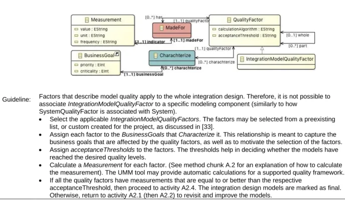
Guideline: Factors that describe model quality apply to the whole integration design. Therefore, it is not possible to associate IntegrationModelQualityFactor to a specific modeling component (similarly to how
SystemQualityFactor is associated with System).
Select the applicable IntegrationModelQualityFactors. The factors may be selected from a preexisting list, or custom created for the project, as discussed in [33].
Assign each factor to the BusinessGoals that Characterize it. This relationship is meant to capture the business goals that are affected by the quality factors, as well as to motivate the selection of the factors.
Assign acceptanceThresholds to the factors. The thresholds help in deciding whether the models have reached the desired quality levels.
Calculate a Measurement for each factor. (See method chunk A.2 for an explanation of how to calculate the measurement). The UMM tool may provide automatic calculations for a supported quality framework.
If all the quality factors have measurements that are equal to or better than the respective
acceptanceThreshold, then proceed to activity A2.4. The integration design models are marked as final. Otherwise, return to activity A2.1 (then A2.2) to revisit and improve the models.
Application example: See Section 6.
5.3 Stage 3: Transforming the Integration Design into an Integration Solution
The third stage of the methodology (i.e. activity A3) starts once the integration design models reach an acceptable quality level, as described in method chunk A2.3. The integration models are extended to cover the necessary details of the integration platform, as well as the mappings and transformation rules that will be used to generate the solution. Figure 5 illustrates the sub-activities of activity A3. The details of the sub-sub-activities are described with the help of the method chunks presented below (see Tables 8-12).
Table 8. Definition of method chunk A3.1
Chunk ID: A3.1 Name: Design Integration Platform Model Type: Atomic
Objective: Describe the architectural components of an integration platform using the UMM. Reuse situation: Human.Designer
Application Technology.Integration Platform
System Engineering Activity.Design.Architecture Design
System Engineering Activity.Model-Driven Development.Modeling
Reuse intention: Enable the components of an integration platform to be referred to by other views of the UMM. Interface:
Situation: The integration platform that is chosen to implement the integration solution. Body:
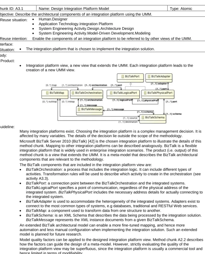
Product:
Integration platform view, a new view that extends the UMM. Each integration platform leads to the creation of a new UMM view.
Guideline:
Many integration platforms exist. Choosing the integration platform is a complex management decision. It is affected by many variables. The details of the decision lie outside the scope of the methodology.
Microsoft BizTalk Server 2010 (BizTalk) [42] is the chosen integration platform to illustrate the details of this method chunk. Mapping to other integration platforms can be described analogously. BizTalk is a flexible integration platform that is widely used in enterprise integration scenarios. The product (i.e. output) of this method chunk is a view that extends the UMM. It is a meta-model that describes the BizTalk architectural components that are relevant to the methodology.
The BizTalk components that are included in the integration platform view are:
BizTalkOrchestration: a process that includes the integration logic. It can include different types of activities. Transformation rules will be used to describe which activity to create in the orchestration (see activity A3.3).
BizTalkPort: a connection point between the BizTalkOrchestration and the integrated systems. BizTalkLogicalPort specifies a point of communication, regardless of the physical address of the integrated system. BizTalkPhysicalPort includes the necessary address details for actually connecting to the integrated system.
BizTalkAdapter is used to accommodate the heterogeneity of the integrated systems. Adapters exist to connect to the most common types of systems, e.g databases, traditional and RESTful Web services.
BizTalkMap: a component used to transform data from one structure to another.
BizTalkSchema: is an XML Schema that describes the data being processed by the integration solution. BizTalkMessage represents the XML instance documents from a given BizTalkSchema.
An extended BizTalk architectural model can enable a more fine-tuned mapping, and hence more automation and less manual configuration when implementing the integration solution. Such an extended model is planned for future research.
Model quality factors can be applied to the designed integration platform view. Method chunk A2.2 describes how the factors can guide the design of a meta-model. However, strictly evaluating the quality of the integration platform view may be superfluous, since the integration platform is usually a commercial tool and hence limited in terms of modifiability.
Application example: See Section 6.
Table 9. Definition of method chunk A3.2
Chunk ID: A3.2 Name: Map Design Model to Integration Platform Type: Atomic
Objective: Identify which architectural components of an integration platform will implement the modeling components of the integration design.
Reuse situation: Human.Designer
Application Domain.Application Type.Intra-Organization Application
Application Domain.Application Type.Inter-Organization Application
System Engineering Activity.Design.Mapping Design
System Engineering Activity.Model-Driven Development.Transformation Reuse intention: Map the integration model and the integration platform’s architecture model. Interface:
Situation: Integration design as described using the goal, concepts, process, and architecture models. Body:
Product: Integration mapping model, an instance of the Mapping View of the UMM, describing the mapping of integration design modeling components to the integration platform’s architectural components:
Guideline: The platform that will implement the integration solution is a mechanism that is required to complete the method chunk. The platform is described using the integration platform model.
The actual generation of the BizTalk components will be described in a later method chunk using transformation rules. In this method chunk, only the mappings are described.
The guidelines for completing this method chunk are as follows:
Concepts will be described in BizTalk using an XML Schema. Therefore, create a new BizTalkSchema, and create a ConceptMapping relationship to relate the BizTalk schema to the Concepts in the concepts model. The integration designer may choose to logically group concepts in several schemas, instead of including all concepts in one schema. In such cases, create a new BizTalkSchema and a corresponding ConceptMapping relationship for each group of Concepts.
Every integrated system requires a physical port for every concept that it provides (or requires). The system’s interface carries the necessary details for configuring the port. Therefore, create a new BizTalkPhysicalPort and a PhysicalPortMapping relationship for every Provides (Requires) relationship in the integration process model. Connect the PhysicalPortMapping to the Interface and InterfaceType of the System that has the Provides (Requires) relationship.
The integration process will be described in BizTalk using an orchestration. Therefore, create a new BizTalkOrchestration, and create OrchestrationMapping relationships to relate the orchestration to the Processes in the process model (which represent activities). The types and configurations of the orchestration components will be decided with the help of the details of the process model, including the ProcessFlow relationship and the order in which concepts are Produced and Consumed. The system that will implement the orchestration is the system that corresponds to the role responsible for performing the processes.
Create a new BizTalkLogicalPort and a LogicalPortMapping relationship for every Produce (Consume) relationship in the integration process model. The logical ports are related to the orchestration that includes the processes in the process model.
Table 10. Definition of method chunk A3.3
Chunk ID: A3.3 Name: Select Transformation Rules Type: Atomic
Objective: Identify and select the transformation rules suitable for generating the integration solution in a specific platform. Reuse situation: Human.Designer
Application Domain.Application Type.Intra-Organization Application
Application Domain.Application Type.Inter-Organization Application
System Engineering Activity.Model-Driven Development.Transformation Reuse intention: Transformation rules are stored in a repository to enable reuse in similar situations. Interface:
Situation: Mapping between the integration design and the integration platform, as described by the mapping model. Body:
Product: Transformation model, an instance of the Transformation View of the UMM. The model describes which transformation rules will be applied to each mapping.
Guideline: Transformation rules are concrete statements in a specific rules language. They describe how to traverse the design models and generate the mapped architectural components in the integration platform. The details captured by the integration design models provide the configuration details for implementing the integration solutions.
Transformation represents any possible transformation rule. The transformation view is agnostic to the specific transformation language being used.
TransformationLanguage describes the language of a transformation rule.
TransformationType captures details that can help the designer in choosing an appropriate rule to apply to a mapping.
The guidelines for completing this method chunk are as follows: For every Mapping in the mappings model:
The UMM tool presents the Transformations that are associated with that mapping’s MappingType, filtered based on TransformationType and TransformationLanguage suitable for the integration platform.
The designer selects a Transformation and assigns it to the Mapping.
If a suitable Transformation cannot be found, the UMM tool enables the designer to create a new rule, including the rule’s text, language, and type. The tool adds the new rule to the repository.
Application example: See Section 6.
Table 11. Definition of method chunk A3.4
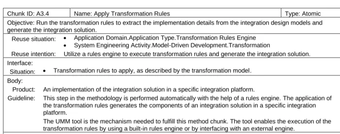
Chunk ID: A3.4 Name: Apply Transformation Rules Type: Atomic
Objective: Run the transformation rules to extract the implementation details from the integration design models and generate the integration solution.
Reuse situation: Application Domain.Application Type.Transformation Rules Engine
System Engineering Activity.Model-Driven Development.Transformation
Reuse intention: Utilize a rules engine to execute transformation rules and generate the integration solution. Interface:
Situation: Transformation rules to apply, as described by the transformation model. Body:
Product: An implementation of the integration solution in a specific integration platform.
Guideline: This step in the methodology is performed automatically with the help of a rules engine. The application of the transformation rules generates the components of an integration solution in a specific integration platform.
The UMM tool is the mechanism needed to fulfill this method chunk. The tool enables the execution of the transformation rules by using a built-in rules engine or by interfacing with an external engine.
Table 12. Definition of method chunk A3.5
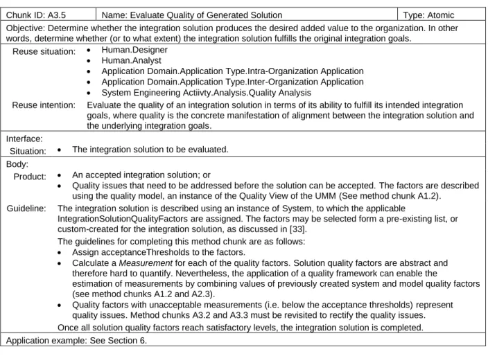
Chunk ID: A3.5 Name: Evaluate Quality of Generated Solution Type: Atomic
Objective: Determine whether the integration solution produces the desired added value to the organization. In other words, determine whether (or to what extent) the integration solution fulfills the original integration goals.
Reuse situation: Human.Designer
Human.Analyst
Application Domain.Application Type.Intra-Organization Application
Application Domain.Application Type.Inter-Organization Application
System Engineering Actiivty.Analysis.Quality Analysis
Reuse intention: Evaluate the quality of an integration solution in terms of its ability to fulfill its intended integration goals, where quality is the concrete manifestation of alignment between the integration solution and the underlying integration goals.
Interface:
Situation: The integration solution to be evaluated. Body:
Product: An accepted integration solution; or
Quality issues that need to be addressed before the solution can be accepted. The factors are described using the quality model, an instance of the Quality View of the UMM (See method chunk A1.2).
Guideline: The integration solution is described using an instance of System, to which the applicable
IntegrationSolutionQualityFactors are assigned. The factors may be selected form a pre-existing list, or custom-created for the integration solution, as discussed in [33].
The guidelines for completing this method chunk are as follows:
Assign acceptanceThresholds to the factors.
Calculate a Measurement for each of the quality factors. Solution quality factors are abstract and therefore hard to quantify. Nevertheless, the application of a quality framework can enable the
estimation of measurements by combining values of previously created system and model quality factors (see method chunks A1.2 and A2.3).
Quality factors with unacceptable measurements (i.e. below the acceptance thresholds) represent quality issues. Method chunks A3.2 and A3.3 must be revisited to rectify the quality issues. Once all solution quality factors reach satisfactory levels, the integration solution is completed. Application example: See Section 6.
6
An Example Business Case
This section presents an example business case that demonstrates the application of the proposed quality-driven methodology for designing an integration solution. The case describes a fictional non-governmental organization (NGO) called Aid&More that conducts humanitarian aid projects to help people in distress situations, e.g. following natural disasters or during armed conflicts. Aid&More relies on external donors to fund its projects. A good public image is therefore important for attracting more donations, which in turn contributes to better project execution and increased impact of the projects. Considering the rising importance of social media in maintaining the public image, Aid&More wishes to automate the management of its social media presence, including the following:
Publishing updates from on-going projects to social media;
Monitoring and analysing mentions (likes, tags, etc.) of Aid&More and its projects; and
Reporting the analysis results to project directors and members of the board.
To achieve the objectives of Aid&More in managing its social media presence, the proposed quality-driven methodology is used to design an integration solution. The quality of the candidate systems for integration is evaluated in Stage 1. The quality of the integration design models is evaluated in Stage 2. The quality of the resulting integration solution is evaluated at the end of Stage 3.
managing the graphical representations. The following sections go through different parts of the integration design models and discuss the output of the steps of the methodology.
6.1 Stage 1 Models
The first step in the methodology is to model the integration-related business goals, following method chunk A1.1. The resulting goal model for the case of Aid&More is illustrated in Figure 6. It represents the final version that is produced following additions, improvements, and quality checks as described in subsequent method chunks. The scope of the model extends beyond the integration solution. The integration goals, described by the leaves in the goal model, ultimately contribute to the fulfillment of the two topmost goals of Aid&More.
Next, the candidate systems are modeled according to the guidelines of method chunk A1.2. Six candidate systems are initially identified to fulfill the integration goals:
PROM: the project management system internally used by Aid&More.
CommuNet: a system used for secure internal communication between the employees.
The social media platforms Facebook, Instagram, and Twitter.
AnalysThis, a cloud-based data analysis service.
Figure 6. Goal model of the integration solution for the case of Aid&More
Figure 7 illustrates part of the resulting systems model, covering CommuNet, Twitter, and Instagram. The figure shows the systems’ interface details as well as the provided/required concepts. It also shows the integration goals for which each system is responsible, described via the system’s role. Finally, system quality factors are defined for each system, along with relevant measurements. The complete systems model includes similar details for the other systems.
“historical data.” By calculating measurement values and applying the calculation algorithm of “Freshness,” the designer ends up with a summary value that can help compare Twitter to other social media platforms. The quality factors can thereby help in choosing the candidate systems that best contribute to the quality of the integration solution.
Upon the completion of method chunk A1.2, any integration goals that lack a responsible system will lead to the initiation of method chunk A1.3. This may come as a result of a system being disqualified from the solution for insufficient quality, or because there was no available systems to fill the required role in the first place. When a new candidate system is identified, method chunk A1.1 is repeated to capture the system’s details and evaluate its quality factors.
Figure 7. Systems model of the integration solution for the case of Aid&More, including system quality factors and measurements
The next method chunk, A1.4, describes how to elicit the integration-related concepts, based on the interfaces and concepts of the candidate systems. Figure 8 illustrates a part of the resulting concepts model. Figures 7, 9, and 10 refer to concepts (from the concepts model) that are associated with the relevant systems, processes, and mappings, respectively.
6.2 Stage 2 Models
Stage 2 of the methodology is where the components of the integration solution come together. Method chunk A2.1 describes how to design the integration process. The resulting process model for managing the social media presence of Aid&More is illustrated in Figure 9. The model reveals how the concepts that are provided/required by the integrated systems are routed and manipulated to achieve the integration goals. It also reveals which systems are responsible for the execution of which processes. The integration solution is represented as a system that is responsible for all processes.
Figure 8. Concepts model of the integration solution for the case of Aid&More
Figure 9. Integration process model of the integration solution for the case of Aid&More
6.3 Stage 3 Models
The third stage of the methodology covers the steps for transforming the integration design into a concrete implementation in BizTalk [42], the chosen integration environment by Aid&More. Method chunk A3.1 describes creating a model of the architecture of BizTalk. The resulting model is illustrated in method chunk A3.1 (see Table 8). Since the result of method chunk A3.1 is a model extending the UMM, the prototype tool is extended to support the new meta-model. This is a one-off task, since the new UMM extension can be reused in other cases that rely on BizTalk as the integration platform.
Next, the components of the integration design need to be mapped to components of the BizTalk-based integrated solution. Method chunk A3.2 describes the necessary steps. Figure 10 illustrates a part of the mapping model for the integration process that was presented above.
Figure 10. Mapping model of the integration solution for the case of Aid&More
The following method chunk, A3.3, describes selecting (or defining, when necessary) transformation rules to apply to the mappings model. Transformations are platform-dependent and will refer to concrete BizTalk components. The methodology allows the integration designer to select a suitable rules language to describe the transformations. Executing the transformation rules (i.e. method chunk A3.4) will generate the BizTalk-based integration solution. The rules engine used to run the transformation depends on the chosen rules language. The prototype tool needs to have built-in support for defining, selecting, and executing transformations. The system and model quality factors that were evaluated earlier influence the solution-wide factors, which can be evaluated once the integration solution has been generated in method chunk A3.5. Due to space considerations, examples of transformations and their execution are not included in the presented case.
7
Discussion and Concluding Remarks
commercial products, with no direct connection to organizational goals [2], despite its importance to the wellbeing and growth of the organization.
This article proposes a quality-driven and model-driven methodology for designing and developing IS integration solutions. The methodology supports creating holistic and consistent integration designs. It extends the notion of integration decision support as described in [10] to the design of the integration solution itself. The methodology outlines the steps necessary for creating IS integration solutions, starting with identifying the integration-related business goals and ending with the generation of the integration solution in a chosen integration platform. The integration designers are thereby relieved of the burden of planning, enabling them to focus on the content of the integration design. By specifically targeting the proposed methodology towards IS integration, this article highlights the importance of IS integration as a top management concern that spans several technological domains and areas of expertise.
Being model-driven, the methodology advocates viewing the design models as part of the integration solution, rather than being an intermediate planning or support step, which is the traditional stance in software development methodologies [24]. Instead of separating the integration requirements and the solution design, e.g. as done in [23], the requirements are captured by the different design views and effectively integrated with the solution design.
The methodology relies on a formally defined meta-model, the UMM, to capture the details at different stages of the integration design. The organizational constituent of IS integration, described as decision justification [21] or the “business without” [23], is captured as underlying motivation for the integration design with the help of the goals view of the UMM. The remaining UMM views capture the integrated data, integration process, integrated systems, and the mapping to the implementation platform. The dependency and traceability between the technical and organizational components of integration [23] are achieved using IMRs that inherently relate the views of the UMM. The progression of the methodological steps is guided by integration quality factors, defined previously in [33] and captured as part of the integration design with the help of the quality view, an extension to the UMM. The stages of the proposed methodology are structured using the IDEF0 notation [38], and the details of each stage were captured using method chunks [40] to ensure consistency and completeness in the description. Furthermore, the UMM provides a modeling foundation capable of consistently and uniformly describing different perspectives of the organization and the IS integration solution.
The proposed methodology strives to address the integration dimensions described in the literature (see Section 3.2). Many of the proposed method chunks (namely A1.2, A1.3, A2.2, A2.3, A3.1, A3.2, and A3.3) account for the “distribution” and “autonomy” dimensions of integration solutions [8]. They achieve this by containing guidelines for describing, evaluating the quality of, and transforming the integration architecture in terms of its individual integrated systems (and their corresponding roles). Using the UMM to describe different types of systems, communication protocols, data structures, and implementation platforms helps in fulfilling the “heterogeneity” [8] and “formalization” [15] dimensions. Furthermore, the views of the UMM cover both organizational and IS-related design details and ensure support for the “variable focus” dimension [15]. Evaluation of the models with the help of the integration quality factors and support of the prototype tool contributes to the “consistency” dimension [15]. The model completeness quality factor specifically accounts for the “comprehensiveness” dimension [15]. Finally, the “flow” and “participation” dimensions [15] are embedded in the definition of the methodological guidelines.
The methodology does not promote any specific quality framework for identifying and evaluating quality factors and measurements. Rather, the methodology provides broad guidelines for applying any chosen quality framework with a specific focus on designing and developing IS integration solutions.