http://www.sciencepublishinggroup.com/j/ijmea doi: 10.11648/j.ijmea.20170503.15
ISSN: 2330-023X (Print); ISSN: 2330-0248 (Online)
Design of Multi Hole Machining Equipment for Flange Parts
Based on CAD/CAM
Shuangxi Jing, Xiaoyu Yang, Chenxu Luo, Jinle Yuan, Zhipeng Luo
School of Mechanical and Power Engineering, Henan Polytechnic University, Jiaozuo, China
Email address:
[email protected] (Shuangxi Jing), [email protected] (Xiaoyu Yang), [email protected] (Chenxu Luo), [email protected] (Jinle Yuan), [email protected] (Zhipeng Luo)
To cite this article:
Shuangxi Jing, Xiaoyu Yang, Chenxu Luo, Jinle Yuan, Zhipeng Luo. Design of Multi Hole Machining Equipment for Flange Parts Based on CAD/CAM. International Journal of Mechanical Engineering and Applications. Vol. 5, No. 3, 2017, pp. 168-174.
doi: 10.11648/j.ijmea.20170503.15
Received: April 1, 2017; Accepted: April 13, 2017; Published: May 23, 2017
Abstract:
According to the situation of multi hole machining with linear circular flange flange parts, a device is analyzed and designed, which can process multiple flange holes at the same time, and the design of the device including fixture design and multi spindle box design. the three - dimensional modeling and analysis software is used, make a study on the design and manufacture of the flange hole of the 96 pipe sleeve, through the selection of hardware, such as drill bits, machine tools, gears, shafts, and the simulation of Ansysworkbench force of main parts, obtain the design device and the processing method suitable for mass production of linear round flange parts with seat. It also can achieve drilling, reaming and tapping function conversion by adjusting the speed and dril.Keywords:
Drill, Multi Spindle, Porous Machining, Flange, CAD/CAM1. Introduction
At present, the design and manufacture based on CAD/CAM (Computer Aided Design/Computer Aided Manufacturing) are more and more popular, introduce CAD/CAM into the design of multi spindle head, which can effectively improve the design efficiency, such as the design of multi spindle head performance parameters, sketch design, evaluation of design results, design knowledge storage and so on [1]. Now four methods are used in China's machinery industry, which are the manual marking punch, multi spindle drilling machine drilling, CNC (Computerized Numerical Control) machine tool drilling and ordinary drilling machine combine of multi spindle device drilling [2]. For large quantities of parts, the precision and efficiency of manual drilling are relatively low, not only waste time, but waste energy; fine-tuning of the processing hole position can be achieved in multi spindle drilling machine, high efficiency, but high cost; for CNC machine tool spindle drilling, the cost is higher, and the efficience is lower; the common drilling machine with multi spindle equipment has strong flexibility, low cost and high efficiency, so for processing with linear circular porous flange type parts in large quantities, the design of a multi spindle equipment with a common drill
Machine is affordable [5]. Multi spindle device, that is the power of a shaft can be transmited to the other two or more axes through a device, can achieve not the effect of multi axis linkage, but the simultaneous drilling, reaming or tapping. Multi spindle head equipment is very common in foreign countries, the domestic multi spindle development rapidly although start late, especially the application of multi spindle device design with computer technology [2]. Multi spindle head design are divided into fixture design, multi spindle gearbox design, the check of main parts. The competition of the enterprise is more and more intense, the introduction of high precision equipment will inevitably increase the cost of the enterprise, so the cost is small and the high efficiency multi spindle device is expected to be found.
2. Texture Design
2.1. The Selection of Drill Bits and Machine Tools
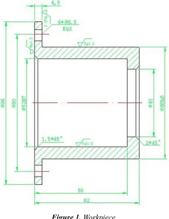
Take the flange hole of the 96 pipe sleeve as an example, as is seen in figure 1. It is known that the material of workpiece is Q235, the machining aperture is Φ6.5, the hole depth is 4.5mm, no special requirements for the accuracy of hole position and shape, so we can use the standard bit with taper shank, which is considered the installation of a number of bits [6].
Figure 1. Workpiece.
The selection of the machine tool includes of the choice of feed rate, the choice of the speed, the torque of the machine and the check of the power of the machine. Temporary selection Z535 vertical drilling machine, which have a wide range of applications in factory. According to the processing requirements, the strength of the drill bit, the strength of machine tool feed mechanism, determine the feed rate is 0.20mm/r, then learned that the axial force of drill F ≤ 2120N. The axial force of Z535 drilling spindle F, so feed f = 0.20mm/r is available [7]. The cutting line speed is
determined by feed and material, that is Vt=15.14m/min, converted into a drill speed:
0
1000 1000 *15.14
741.42r / min * 6.5
v n
d
= = =
π π (1)
According to the working hours of the formula n*f to round speed, calculated as follows:
1 1
2 2
0.18 750 135 / min
0.20 530 106 / min
n f mm
n f mm
× = × =
× = × = (2)
So the n=750r/min, f=0.18mm/r. Check table to determine the torque when drilling, that is Mc=10.94N • M, power is Pc<1.1KW, Z535 drilling machine can meet the processing requirements.
2.2. The Determination of Positioning and Clamping Scheme
The determination of the positioning scheme should be taken into account the accuracy of each part of the surface, the facilitate of the demolition, and the amount of labor. To consider 96 pipe as an example, in order to avoid the extra precision of machining parts or tooling, the positioning scheme using a plane with a fixed V - block, the plane refers to the phi 66 small cylindrical end, V block can be clamped at any one surface of the cylinder with the diameter of 66 [3]. The purpose of the clamping is to make the position of the workpiece to maintain its relative position, no deviation, so the clamping program used: the two active V-blocks are clamped by two positive and negative screw pairs.
The final fixture design results are shown in Figure 2. In addition to the positioning and clamping device, the drilling template need be installed due to the long working length of the drill bit, which in order to prevent the work of the drill bit swing [8]. And in order to save the replacement time of parts, using the method of drilling template moving up and down along with the spindle of the vertical drilling machine, so the parts can be directly removed from the top, which greatly saves the clamping time.
2.3 The Ansysworkbench Simulation of Workpiece in the Fixture
Figure 3. Workpiece of three - dimensional model.
Through the fixture assembly diagram, we can see that the drill bit feeding force is transferred to the base through the workpiece; the V-block plays the role of clamping, and does not bear a direct impact; the flange part directly bears the axial force of the drill bit, which is equivalent to the cantilever beam in the mechanical model, so the flange edge of the workpiece is the most easily damaged [10]. The SolidWorks model of the part is shown in Figure 3. The feed force of the drill bit is calculated:
0.8 n
P =50DS =82.43 Kilogram force( ) (3)
The workpiece is imported into the Ansys 13.0, the material can be definitioned as Q235, the loading force and constraints as shown in Figure 4. At the moment when the bit is in contact with the workpiece, the center position of the four flange holes must bear the axial force of the drill bit [9]. Therefore, A is the fixed constraint of small outer surface, B, C, D, E are the axial pressure of the bit to the workpiece.
Figure 4. Force and restraint.
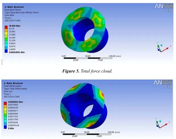
The total stress nephogram and the total deformation nephogram are shown in Figure 5 and 6.
As can be seen from the diagram, the maximum deformation is 0.0083815mm, which occurs at the edge of the four flanges close to the drill bit; The maximum stress is 25.638MP, and the yield strength is 235MP. Therefore, the clamping style meet the processing requirements.
Figure 5. Total force cloud.
3. The Design of Multi Spindle Box
The design of multi spindle box mainly including the selection and modification of the gear, the determination of the diameter and position of the shaft, the selection of the bearing and the positioning of the shaft, and the design of the main parts of the gearbox [3].
3.1. The Selection and Displacement of the Gear
The selection and design of the gear including the determination of the modulus and the teeth number. The modulus of the primary gear is m = 1.5, determine the transmission ratio according to the speed, the number of teeth on the work axis to select the minimum number of teeth Z3 = 17, which the cut of root will not occur, and then determine the number of gears on the spindle, Calculated as follows:
N n 1 n 741.42 i 1.40 n 530
= = = (4)
1 3
Z =Z ×1.4= ×17 1.4≈24 (5)
The feed of the machine is calculated as follows:
1 N N
S =S ×i =0.18 1.40× =0.25mm / r (6)
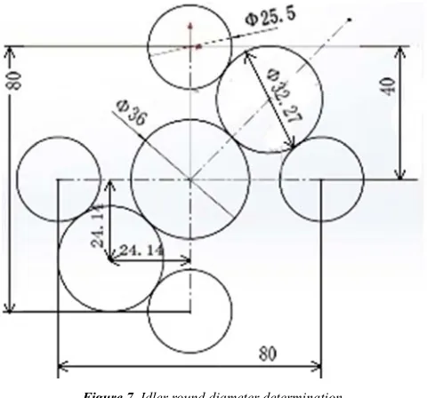
To ensure the same rotation of the drive shaft and the working axis, idler gear number and modulus can be getted from the solidworks software simulation, as shown in Figure 7.
Figure 7. Idler round diameter determination.
As can be seen from the figure, the coordinate of the idler shaft relative to the center of the drive shaft is (24.14, 24.14), the diameter is 32.27mm, Z2 is calculated as follows:
2
d 32.27
Z 21.52
m 1.5
= = = (7)
Select Z2 = 21, and two sets of seven gears need to be displaced.
3.2. The Determine of the Diameter and Position of the Shaft
The shaft diameter of each axis is estimated according to the power and speed, so before the calculation of the shaft diameter of each axis, the power and speed of each axis are needed to calculate [5]. The idler shaft does not transmit torque in the middle, therefore no special requirements.
First calculate the axial force of a single working shaft and the power consumed by a single hole machining, calculated as follows:
2 0.8
Mn =21D S =225.04(Kgf * mm) (8)
0.8 n
P =50DS =82.43 Kgf( ) (9)
The total axial force and power of the drive shaft can be estimated simply by multiplying the number of working axes. According to the relevant calculation formula can be get the following results, and the diameter of the drive shaft can be calculated:
n
P= ×4 P = ×4 82.43=329.72 Kgf =3231.26N
∑
( ) (10)n n
4 M n
N 4 N 0.93 hp 0.68KW
716200
× ×
= × = = =
∑
( ) (11)1 3 min
1 P
d 110 11.95mm
n
≥ × = (12)
In order to increase the safety of the shaft, 11.95mm round to 14mm. The shaft diameter of the working shaft can be appropriately reduced. The position of the working shaft is determined by the hole of the machined part; the position of the drive shaft is in the center of the four holes so that no additional bending moment is generated, the position of the idler shaft is known according to Figure 7. In addition, in order to carry out axial positioning, each axis is often made ladder-like.
3.3. Selection of Bearings and Ensure the Shaft Positioning
Figure 8. Intermediate plate bearing interference check.
Figure 9. the under box bearing interference check.
3.4. The Design of the Main Parts of the Multi-axle Gear Box
The main design parts of the gear box are the connection part with the machine tool, the connection part with the drill bit, the guide part and the box part.
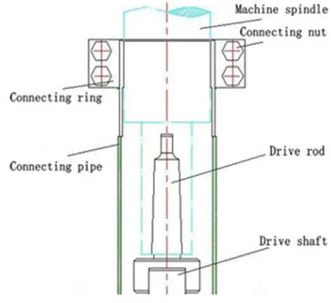
The connecting part with the machine tool is connected with a connecting ring and a connecting pipe, the connecting ring is welded on the connecting pipe, and then a slit is cut along a diameter, the connecting sleeve is fixed on the main shaft of the machine tool [4]. Structure as shown in Figure 10. Bit connection part need to ensure the convenience of the drill assembly and disassembly, as well as the reliability of the drill bit, the specific design shown in Figure 11.
The guide part should give the drilling template an accurate position when the machine tool spindle is feeding, and at least contains the bushing, guide column, spring three parts, design as shown in figure 12.
Figure 10. Machine connection section.
Figure 12. Oriented mechanism design.
The design of the box body should take into account the location of the shaft, the wall thickness and reinstallation of the box.
3.5. Check the Working Shaft in the Multi-axis Head Case
After the design of the multi-spindle head gear box is completed, the gears, shafts and bearings are also need be checked. Since the parameters of the gears and bearings are fixed, the calibration steps are perfect and the shape is fixed. Therefore, the bearings and gears can be checked by the general method. The force analysis of the three shaft are simulated, and the working axis as the last level of the shaft, directly connected with the drill, so it is most vulnerable to damage. The following is a solidworks built three-dimensional model, as shown in Figure 13.
In the case of working, the working shaft is supported by two bearings, the gears that engage the transmission will rotate to the working shaft, while the axis will be supported a certain
radial oppression. To simplify the problem, we can think that the equilibrium relationship exists at this time: The key provides the rotate force of the shaft, and the shaft rotates under the support of the bearing; the force of the gear to the shaft is balanced with the bearing support.
The working shaft model is imported into the ansys13.0, the material is definited as 45, the load and the constraints are added to the shaft, as shown in Figure 14, the torque can be transferred to the shaft through the key[9]. A, B for the bearing support, which limits the 5 degrees of freedom in addition to
Figure 13. Work shaft parts.
Figure 14. Force and restraint.
the axial rotation; C to add the force on the side of the keyway to simulate the torque of the working shaft; D is the radial force of the gear contact to the shaft, which is the superposition of axial force and radial force.
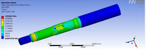
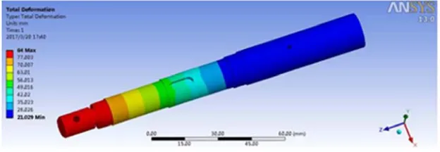
The analysis of the stress nephogram and deformation nephogram is shown in Figure 15 and figure 16.
Figure 16. Total deformation cloud.
According to the software analysis, the maximum stress of the working shaft is 4.0046 * 10 ^ 5MP, and the yield strength of the 45 steel is 3.55 * 10 ^ 8MP; The maximum deformation of the shaft is 84 mm, concentrating on the outer diameter of the smaller diameter. Although the overall strength of the shaft is to meet the requirements, but it also need us to pay attention to the diameter of the shaft at the processing of fillet and reduce stress concentration in the processing of the work shaft.
4. Conclusion
This paper is based on the "96 pipe" as an example, describes the general steps for machining with linear circular flange parts porous, including the analysis of parts of the selection mechanism and material characteristics, machine tool, fixture design, design of multi axle box, ansys Simulation and Analysis of Important Parts in Equipment. Through the assistance of the computer, reducing some of the tedious calculation of the design process, the simulation check of parts with the combination of SolidWorks and ANSYS is to make the results become clear.
References
[1] DING Zhi-qiang, RAO Xi-xin, DING Zhi. Multi-Axis Transmission Intelligence CAD System Based on the Technology of KBE [J]. Mechanical & Electrical Engineering Magazine, 2004 (5): 47-50.
[2] Chong Wang. Study on Multi-Spindle Horizontal Drilling machine Based on Pro/ENGINEER Analysis [D]. Cheng Du:
Sichuan University, 2005:1-55.
[3] Lianggui Pu, Minggang Ji. machine design [M]. BeiJing: Higher Education Press, 2006: 89-103.
[4] Yongsheng Niu, Long Wu, Chunying Jiang, Li Li. Machinery manufacturing technology [M]. XiAn: Shaanxi science and Technology Press, 2002: 47-96.
[5] The first automobile factory equipment design studio. Multi spindle design of gear transmission [M]. Beijing: Machinery Industry Press, 1979: 1-85.
[6] Aizhen Wang. Engineering materials and forming technology [M]. Beijing: Machinery Industry Press, 2003: 22-65.
[7] Xing Ai, Shigang Xiao. Concise Handbook of cutting parameters [S]. Beijing: Machinery Industry Press, 1994: 1-78.
[8] Mingwang Li. Concise Handbook of machine tool fixture [S]. Beijing: Chemical Industry Press, 2003: 13-61.
[9] Jingjin Xu. Ansys Workbenc project examples [M]. Beijing: People's Posts and Telecommunications Press, 2016: 13-32.