IMPROVED DYNAMIC
RECONFIGURATION IN DISTRIBUTED
SWITCH-BASED INTERCONNECTED
SYSTEMS
NARESH KUMAR
University Institute of Engineering & Technology, Kurukshetra University Kurukshetra Haryana -136118, India
RENU VIG
University Institute of Engineering & Technology , Panjab University Chandigarh-160014, India
DEEPAK BAGAI
Punjab Engineering College(Deemed University) Chandigarh-160014, India
Abstract :
Todays distributed switch-based interconnected systems require high performance, reliability and availability. These systems changes their topologies due to hot expansion of components, link or node activation and deactivation. Therefore, a dynamic reconfiguration algorithm updates the routing tables of these interconnected switches according to new changed topology without stopping the traffic. Here, we propose an improved deadlock-free partial progressive reconfiguration (PPR) technique based on UP/DOWN routing algorithm that assigns the directions to various links of high-speed switched networks based on pre-order traversal of computed spanning tree. This new technique gives better performance as compared to traditional PPR such as increasing throughput and reducing latency by optimizing the best use of all interconnected links of the network. The simulated results are compared with existing PPR.
Keywords: Deadlock avoidance, dynamic reconfiguration, UP/DOWN routing, fault tolerance, high-speed networks .
1. Introduction
High-performance switch-based interconnected systems require communication between various workstations when there is change in network topologies due to hot expansion of components, failure of links or switches. In past years, many technologies have been proposed to reconfigure the network in case of addition/removal of links/switches without stopping the transmission of packets. Current high-speed switched networks (Myrinet[2,8], Advanced Switching[1], Infiniband[5], Tnet[9]) updates their routing tables when there is change in network topologies due to network components failures and addition of new one. In such cases a dynamic reconfiguration algorithm analyze the new network topology and updates the routing table by replacing the old routing function with the new updated routing function. Although both routing functions are deadlock-free still it may create deadlock during reconfiguration because one of the routing function may take turns that are not allowed in the other routing function by making a cycle in the network.
In the literature, static reconfiguration (designed for Autonet[13,15] and Myrinet[2,8] networks) replaces the routing function from old to new by stopping the network traffic. Hence it creates negative impact on the network service availability and the performance of the overall network degrades.
links/nodes and are known as dynamic reconfiguration techniques.(Partial Progressive Reconfiguration (PPR)[3], Skyline[6], Double scheme[10], and Simple Reconfiguration [7]), NetRec[16] and Dynamically scaling Algorithm(DSA) [17]. These schemes are designed for the networks that uses distributed routing. Double Scheme requires extra resources like virtual channels for deadlock handling that occur during transition of old routing function to new routing function. Simple reconfiguration requires a special packet called token to avoid deadlock. In this scheme firstly all packets are transmitted by old routing function, then token and finally the packet transmission is based on new routing function. NetRec was proposed as a dynamic reconfiguration scheme to increase the network availability in the presence of a permanent node fault. It restores the network connectivity by building a tree that spans all immediate neighbours of the faulty node that are still connected to network. The NetRec Scheme[16] requires every switch to maintain information about nodes some number of hops away and is only applicable to wormhole networks. NetRec is extended to dynamically reconfigure the network for the case of newly joining nodes called Dynamically Scaling Algorithm (DSA). The solution in DSA is based on performing sequence of partial routing table updates, while dropping the user messages in all selected nodes until the restoration is completed. PPR requires a sequence of synchronizing steps to progressively update old forwarding table entries to new ones while ensuring that no cycles form. The PPR [3] approach correct an invalid UP/DOWN graph after change in network topology. Double Scheme[10] uses the concept of virtual channels to avoid deadlock while reconfiguring the network . Simple Reconfiguration [7] uses a packet called a token to avoid deadlock by ensuring that the packet which belongs to old routing function are transmitted first, then the token, and finally packet transmission is based on the new routing function. A management mechanism[11,12] and zero-configuration hierarchical UP/DOWN routing[19] has been discussed for distributed calculation of the new routing function when there is any change in the switched-network topology. In this mechanism the distributed path-computation gives better performance when compared to existing centralized path-computation, still the routing function was updated statically, therefore degrades the performance.
In this research work, we propose to apply a new and very efficient dynamic reconfiguration strategy based on PPR that makes transformation of an invalid UP/DOWN graph (that is due to change in topology) into a valid UP/DOWN graph, while ensuring that there is no cycles in the graph to make it deadlock-free. Moreover, our dynamic reconfiguration does not use any additional resources such as virtual channels or special packet a token. This new proposed scheme gives better performance than PPR by distributing the traffic through optimize use of all links and reducing the congestion on root node of the spanning tree.
The next section discuss the concepts of UP/DOWN routing based PPR scheme and provides background information on previous studies of reconfiguration of UP/DOWN routing networks. Section 3 gives the details of improved dynamic reconfiguration strategy and assigning the directions UP/DOWN to the operational links based on pre-order traversal of spanning tree. In section 4, the performance of the proposed reconfiguration strategy is evaluated. Finally, section 5 concludes this research work and proposes some future work.
2. UP/DOWN Routing based Dynamic Reconfiguration (PPR)
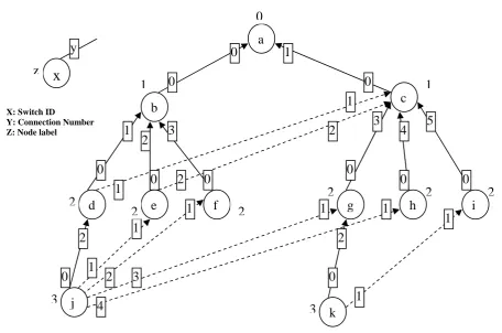
Fig 1: Example of UP/DOWN direction assignment in a switched network.
Switch a b c d e f g h i j k
a [x] [0] [1] [0,1] [0,1] [0] [1] [1] [1] [0,1] [1]
b [0] [x] [0] [1] [2,0] [3] [0] [0] [0] [1,2,3,0] [0]
c [0] [0] [x] [1,0] [2,0] [0] [3] [4] [5]
[1,2,
3,4,0] [3,5] d [0,1] [0,1] [1,0] [x] [0,1] [0] [1,0] [1,0] [1,0] [2,1,0] [1,0] e [0,2] [0,2] [2,0] [0,2] [x] [0] [2,0] [2,0] [2,0] [1,2,0] [2,0] f [0] [0] [0] [0] [0] [x] [0] [0] [0] [1,0] [0] g [0] [0] [0] [0] [0] [0] [x] [0] [1,0] [2,0] [0] h [0] [0] [0] [0] [0] [0] [0] [x] [0] [1,0] [0]
i [0] [0] [0] [0] [0] [0] [0] [0] [x] [0] [1 ,0]
j
[0,1,2, 3,4]
[0,1,2, 3,4]
[1,3,4 ,2,0]
[0,1, 2,3,4]
[1,2,0 ,3,4]
[2,1, 0,3,4]
[3,4, 2,1,0]
[4,3,2, 1,0]
[4,3,2
,1,0] [x] [4,3,2
,1,0] k [0,1] [0,1] [0,1] [0,1] [0,1] [0,1] [0,1] [0,1] [1,0] [0,1] [x]
Table 1: Routing table based on UP/DOWN algorithm for Fig 1
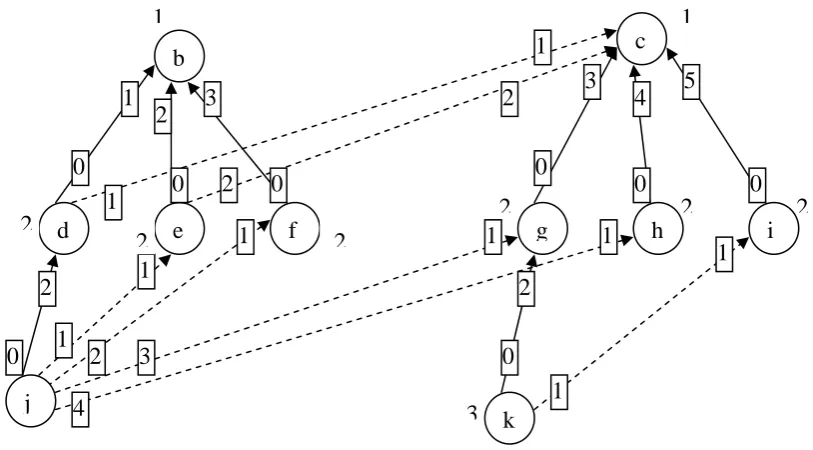
A sink node [3] does not have outgoing up-links( a node that is not the source of any link). There are no legal routes between any two sink nodes due to the restrictions imposed by UP/DOWN routing algorithm because each route would require a down to up transition, which is not allowed. So there is always a single sink node in directed acyclic graph based on UP/DOWN routing algorithm. A break node is the source of two or more links. This node breaks the cycles formation to avoid deadlock in directed graph. The graph of Fig 1 includes various break nodes like node j, e, d. A correct graph contains a single sink node for UP/DOWN routing. It includes as many break nodes as necessary to break all cycles for deadlock freedom. The graph shown in Fig 1 is a correct graph. On the other hand, an incorrect graph does not meet the restrictions imposed in the correct graph. An incorrect graph has the absence of a sink node, presence of more than one sink node, or there are cycles in the graph. Fig. 2 tells about an incorrect graph with two sink nodes ‘b’ and ‘c’ after removal of node ‘a’ from Fig. 1 correct graph.
a
b
c
d
e
f
g
h
i
j
k
0
0
1
1
2
3
0
1
2
3
4
5
0
1
2
0
1
2
0
1
0
1
2
0
1
1
0
0
1
2
3
4
0
1
0
1
1
2
2
2
2
2
2
3
3
x
y
z
X: Switch ID
Fig. 2 After deactivation of root node ‘a’ of Fig. 1 (Incorrect graph)
A PPR scheme changes the direction of operational links to give a correct graph from an incorrect graph as shown in Fig. 3
Fig 3 A new directed acyclic correct UP/DOWN graph after deactivation of root node ‘a’ of Fig. 1 (new correct graph after deactivation)
Switch b c d e f g h i j k
b [x] [2] [1] [2] [3] [1,2] [1,2] [1,2] [1,2,3] [1,2]
c [1,2] [x] [1,2] [2,1] [1,2] [3] [4] [5]
[3,4,
1,2] [3,5]
d [0] [1,0] [x] [0] [0] [1,0] [1,0] [1,0] [2,1,0] [1,0]
e [0] [2,0] [0] [x] [0] [2,0] [2,0] [2,0] [1,2,0] [2,0]
f [0] [0] [0] [0] [x] [0] [0] [0] [1,0] [0]
g [0] [0] [0] [0] [0] [x] [0] [0] [1,0] [2,0]
h [0] [0] [0] [0] [0] [0] [x] [0] [1,0] [0]
i [0] [0] [0] [0] [0] [0] [0] [x] [0] [1,0]
j [0,1,2 ,3,4] [0,1, 3,4,2] [0.1.2 .3.4] [1,0,2 ,3,4] [2,0, 1,3,4] [3,0, 1,2,4] [4,0, 1,2,3] [3,4 ,0,1,2] [x] [3,0, 1,2,4]
k [0,1] [0,1] [0,1] [0,1] [0,1] [0,1] [0,1] [1,0] [1,0] [x]
TABLE 2: Routing table for Fig 3 based on old PPR after deactivation of node ‘a’ of Fig. 1
b
c
d
e
f
g
h
i
j
k
1
2
3
1
2
3
4
5
0
1
2
0
1
2
0
1
0
1
2
0
1
1
0
0
1
2
3
4
0
1
1
1
2
2
2
2
2
2
3
3
b
c
d
e
f
g
h
i
j
k
1
2
3
1
2
3
4
5
0
1
2
0
1
2
0
1
0
1
2
0
1
1
0
0
1
2
3
4
0
1
1
1
2
2
2
2
2
2
3
In the literature, several algorithms have been proposed for constructing an UP/Down directed graph. Traditional proposals are based on the computation of a spanning tree which is built using a breadth-first search (BFS)[14], a depth-first search(DFS)[13], or a propagation-order spanning tree(POST) [15].
3. An improved PPR scheme based on pre-order traversal of spanning tree
Network topology changes due to addition/removal of switches/ links, then our dynamic reconfiguration scheme calculates a new routing function which ensures that packets that belong to the new routing function can not take turns in the old routing function, and vice versa. Therefore, packets of old and new routing functions can unrestrictedly coexist in the network without creating deadlocks. This improved PPR scheme is based on the concept of assigning the UP/DOWN directions to operational links by pre-order traversal of spanning tree in which a unique label is for each node of the graph. We also present lemmas to support that, when an UP/DOWN graph for the new topology is designed based on pre-order traversal of spanning tree, the routing function is updated without the risk of transient deadlocks.
Definition 1
Assume that two UP/DOWN directed graphs, G1 and G2, represented two network topologies. Then G1 and G2 are corrected.
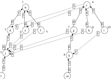
Fig 4 presents UP/DOWN graph G1 which is correct. Fig. 5 shows again a correct graph G2 after removal of root node ‘a’ of graph G1 in Fig.4.
Lemma1
Assume that an UP/DOWN directed graph G1 based on pre-order traversal of spanning tree is correct. Then, it is always possible to obtain a correct graph G2 from G1 when any node or link is added or removed.
Proof
In a correct UP/Down graph, each possible cycle must contain at least one node with two incoming up-links and at least one node with two outgoing up-links. For each possible cycle in G2, we have three options with respect to break node placement. Thus, it is always possible to construct a correct graph G2 which is also like G1. A correct graph G1 in Fig 4 gives a new correct graph G2 in Fig 5 after removal of root node ‘a’ with new root node ‘b’ or correct graph G3 as shown in Fig 6 from graph G2 while addition of new nodes ‘l’ and node ’m’. Lemma 2
Assume that two up/down directed graphs G1 and G2 where G2 is also correct after removal of any node or link of correct graph G1.
Proof
Assume that G2 is a subgraph of G1 in which each link that connects a break node in G1 with the corresponding break node in G2 is suppressed, and that G2 is a correct UP/DOWN graph. Then, according to lemma 1, we can guarantee that G2 is also a correct UP/DOWN graph. Thus it possible to define a fully connected deadlock-free routing function R2 over G2. R2 satisfies the routing-restrictions of both G1 and G2 since all the break nodes either have the same locations or have been removed.
Switch a b c d e f g h i j k
a [x] [0] [1,0] [0] [0] [0] [1,0] [1,0] [1,0] [0] [1,0]
b [0] [x] [0,2,1] [1] [2,1] [3,1] [0,1] [0,1] [0,1] [1] [0,1]
c [0,1,2] [0,1] [x] [1,0,2] [2,0,1] [0,1,2] [3,2, 1,0]
[4,2, 1,0]
[5,3,
2,1,0] [2,1,0] [3,2, 1,0] d [0] [0] [1,0,2] [x] [0,2] [0,2] [1,2,0] [1,2,0] [1,0,2] [2] [1,2,0] e [0,1] [0,1] [2,0] [0,1] [x] [0,1] [1,2,0] [1,2,0] [2,0,1] [1,0] [1,2,0] f [0,1] [0,1] [0,1] [0,1] [0,1] [x] [1,0] [1,0] [1,0] [1,0] [1,0] g [0,1] [0,1] [0,1] [1,0] [1,0] [1,0] [x] [0,1] [0,1,2] [1,0] [2] h [0,1] [0,1] [0,1] [1,0] [1,0] [1,0] [1,0] [x] [0,1] [1,0] [1] i [0,1] [0,1] [0,1] [0,1] [0,1] [0,1] [0,1] [0,1] [x] [0,1] [1,0]
j [0] [0] [0] [0] [1,0] [2,0] [3,0] [4,0] [3,1,0] [x] [3,1,0]
k [0] [0] [0] [0] [0] [0] [0] [0] [1,0] [0] [x]
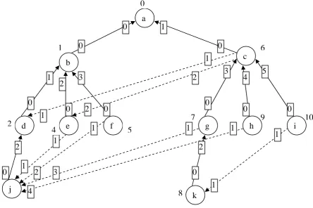
Fig. 4. Pre-order traversal based UP/DOWN routing algorithm (correct graph G1)
Fig 5. After deactivation of root node ‘a’ of G1 of Fig. 4 gives Correct graph G2
3.1 Preorder Traversal Based UP/DOWN direction assignment to various links. 1. Computing a spanning tree.
2. Preorder traversal of spanning tree and assign labeling to nodes through horizontal traversal based distance of each node from root node.
3. Next assigning UP/DOWN directions to various links likewise previous strategy. 4. Finally, updation of routing tables.
b
c
d
e
f
g
h
i
j
1
2
3
1
2
3
4
5
0
1
2
0
1
2
0
1
0
1
2
0
1
1
0
0
1
2
3
4
0
1
1
6
2
4
5
7
9
10
3
8
k
a
b
c
d
e
f
g
h
i
j
k
0
0
1
1
2
3
0
1
2
3
4
5
0
1
2
0
1
2
0
1
0
1
2
0
1
1
0
0
1
2
3
4
0
1
1
6
2
4
5
7
9
10
3
3.1.1 Switch Deactivation
The deactivation of switch including the root node produces a new root node. Switch deactivations imply that messages routed to remove components must be discarded. In this case, shorter reconfiguration time implies less discarded messages which is the characteristic of this improved PPR scheme.
Switch b c d e f g h i j k
b [x] [1,2] [1] [2,1] [3,1] [1,2] [1,2] [1,2] [1] [1,2]
c [1,2] [x] [1,2] [2,1] [2,1] [3,2,1] [4,2,1] [5,2,1] [1,2] [3,2,1] d [0] [1,2,0] [x] [0,2] [0,2] [2,1,0] [2,1,0] [1,0,2] [2] [1,2,0] e [0,1] [2,1,0] [0,1] [x] [0,1] [2,1,0] [2,1,0] [2,1,0] [1,0] [2,1,0] f [0,1] [0,1] [0,1] [0,1] [x] [1,0] [1,0] [1,0] [1,0] [1,0] g [0,1] [0,1] [0,1] [0,1] [1,0] [x] [0,1] [0,2,1] [1,0] [2,1,0] h [0,1] [0,1] [0,1] [0,1] [1,0] [0,1] [x] [0,1] [1,0] [0,1] i [0,1] [0,1] [0,1] [0,1] [0,1] [0,1] [0,1] [x] [1,0] [1,0] j [0] [1,0] [0] [1,0] [2,0] [3,0] [4,0] [3,1,0] [x] [3,1,0]
k [0] [0] [0] [0] [0] [0] [0] [1,0] [0] [x]
Table 4: Routing table for Fig 5 after deactivation of node ‘a’ of Fig 4
3.1.2. Switch Activation
When a new switch is added, a direction must be assigned to the links connecting to it in such a way that the down direction goes toward the new switch and it should no produce cycles in the directed graph.
Fig 6. Activation of new switches ‘l’ and ‘m’ does not effect the graph G2 of Fig. 5 (new correct graph G3 after activation)
b
c
d
e
f
g
h
i
j
1
2
3
1
2
3
4
5
0
1
2
0
1
2
0
1
0
1
2
0
1
1
0
0
1
2
3
4
0
1
1
6
2
4
5
7
9
10
3
8
k
l
5
0
switch b c d e f g h i j k l m b [X] [1,2] [1] [2,1] [3,1] [1,2] [1,2] [1,2] [1] [1,2] [1] [1,2] c [1,2] [X] [1,2] [2,1] [2,1] [3,2,1] [4,2,1] [5,2,1] [1,2] [3,2,1] [1,2] [3,2,1] d [0] [1,2,0,] [X] [0,2] [0,2] [2,1,0] [2,1,0] [1,0,2] [2] [1,2,0] [2] [2,1,0] e [0,1] [2,1,0] [0,1] [X] [0,1] [2,1,0] [2,1,0] [2,1,0] [1,0] [2,1,0] [1,0] [1,2,0] f [0,1] [0,1] [0,1] [0,1] [X] [1,0] [1,0] [1,0] [1,0] [1,0] [1,0] [1,0] g [0,1] [0,1] [0,1] [0,1] [1,0] [x] [0,1] [0,2,1] [1,0] [2,1,0] [1,0] [2] h [0,1] [0,1] [0,1] [0,1] [1,0] [0,1] [X] [0,1] [1,0] [0,1] [1.0] [0,1] i [0,1] [0,1] [0,1] [0,1] [0,1] [0,1] [0,1] [X] [1,0] [1,0] [1,0] [1,0] j [0] [0,1] [0] [1,0] [2,0] [3,0] [4,0] [3,1,0] [X] [3,1,0] [5] [3,1,0]
k [0] [0] [0] [0] [0] [0] [0] [1,0] [0] [X] [0] [2]
l [0] [0] [0] [0] [0] [0] [0] [0] [0] [0] [X] [0]
m [0] [0] [0] [0] [0] [0] [0] [0] [0] [0] [0] [X]
Table 5 Routing table for Fig 6 after activation of node ‘l’ and ‘m’ to Fig. 5
4. Performance Evaluation
In this section, we evaluate the performance of the improved PPR algorithm proposed in section 3. Our dynamic reconfiguration scheme is compared to traditional PPR scheme. New mechanism requires very less computations time for updation of routing function from old one to new, when there is change in network topology due to addition or removal of switch nodes or links.
4.1 Switch Model
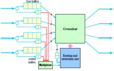
A switch consist of crossbar, a routing and configuration unit, and many full-duplex links. The routing and configuration unit provides the output channel for multiple packets to cross a switch. Table look-up routing is used. Each input channel has 2 set of buffers: user and control buffers. Control buffers handle control messages generated in each reconfiguration process when there is any change in network topology. We have assumed that one clock cycle is required to access the routing table and provide the output link for the message.
Fig. 7 Switch Architecture
. 4.2 Network Model
The high-speed switched networks are consist of a set of switches interconnected through point-to-point links and hosts are connected to those switches through a network interface card in a irregular fashion. We have evaluated the performance of different sizes of networks. Several different networks with irregular topologies are considered in order to perform a detailed study. The irregular topologies have been randomly generated.
4.3 Message Generation
4.4 Simulation Results
In this section, we show the simulation results for improved PPR scheme based on pre-order traversal of spanning tree. The simulation results are compared with existing PPR scheme. The simulation used for this work is developed with the IRFlexiSim Simulator[18]. First of all, we have discussed the way in which the path computation time is reduced by using improved PPR strategy in section 3. In order to increase the accuracy of the results, each experiment is repeated several times. The numbers of simulation runs for each topology are presented graphically. The number of data packets that are discarded during the topology change assimilation process gives an indication of the level of service a network can provide to applications. Fig. 8 compares the amount of packets that are discarded for PPR and improved PPR scheme. The results in Fig 8 shows that, for a switch removal the rate at which data packets are discarded is notably lower for new PPR scheme. The main reason is that, for improved PPR scheme minimum changes are required to update the routing tables. In case of switch additions, no packets are discarded due to inactive ports because no old roots include the switch that was just added. There is no packet discarding when a switch addition occur because it does not destroy any of the existing paths. To conclude this evaluation, Figures as shown below illustrates the instantaneous behavior of both the old PPR and new PPR scheme. The improved PPR scheme reduces the number of packets discarded during reconfiguration and increases the performance by distributing the traffic over all links of the network. Thus, it reduces the latency of packets and increases throughput by optimize use of all links and lowering the congestion at root node as shown in Fig. 9 and Fig. 10.
Discarded Packets 0 20 40 60 80 100 120 140 160 180
8N12L12N16L16N24L24N32L32N48L48N64L 64N 100 L Network Size(Switches) PPR Improved PPR Latency 0 10 20 30 40 50 60
8N12L12N16L16N24L24N32L32N48L48N64L 64N1
00L
Network Size(Switches)
Improved PPR PPR
Fig. 8 Discarded Packets versus network size Fig 9 Instantaneous Latency versus network size
Throughput 0 0.05 0.1 0.15 0.2 0.25 0.3 0.35 8N12 L 12 N 1 6L 16 N 2 4L 24 N 3 2L 32 N 4 8L 48 N 6 4L 64 N100 L
Netw ork Size(Sw itches)
Improved PPR
PPR
Fig. 10 Network throughput versus network size
5.Conclusions and future work
designed to ensure that packets routed according to the old and the new routing functions can unrestrictedly coexist in the network, without the risk of forming deadlocks. Simulation results show that this significantly reduces the amount of packets that are discarded during the topology change assimilation. Moreover, our strategy does not required additional resources such as virtual channels, and it could easily be implemented in current commercial systems. As future work, we plan to extend the proposed methods in order to support other routing algorithms in addition to UP/DOWN.
6. References
[1] http://www.picmg.org (2003) Advanced Switching Interconnect Special Interest Group, Advanced Switching Core Architecture
Specification Revision 1.0
[2] Boden, N.J.,(1995 ) et al.: Myrinet: A gigabit per second LAN. IEEE Micro.
[3] Casado, R., Bermúdez, A., Quiles, F.J., Sánchez, J.L., Duato, J, (2001).: A protocol for deadlockfree dynamic reconfiguration in high-speed local area networks. IEEE Transactions on Parallel and Distributed Systems 12(2)
[4] Dally, W.J., Seitz, C.L,(1987).: Deadlock-free message routing in multiprocessor interconnection networks. IEEE Transactions on Computers 36(5)
[5] http://www.infinibandta.com ,(2002)InfiniBand Architecture Specification (1.2)
[6] Lysne, O., Duato, J,(2000).: Fast dynamic reconfiguration in Irregular networks. In: Proc. Int.Conference on Parallel Processing [7] Lysne, O., Montañana, J.M., Pinkston, T.M., Duato, J., Skeie, T., Flich, J,(2004).: Simple deadlock- free dynamic network
reconfiguration. In: Proc. of the International Conference on High Performance Computing
[8] http://www.myri.com/ (2000) Myrinet, Inc.: Guide to Myrinet-, Switches and Switch Networks
[9] R.Horst, Tnet,(1995): A reliable System area network, IEEE Micro, pp 36-44
[10] Pinkston, T.M., Pang, R., Duato, J,(2003).: Deadlock-free dynamic reconfiguration schemes for increased network dependability. IEEE Transactions on Parallel and Distributed Systems 14(6)
[11] Robles-Gómez, A., García, E.M., Bermúdez, A., Casado, R., Quiles, F.J,(2006).: A Model for the Development of ASI Fabric Management Protocols. In: Nagel, W.E., Walter, W.V., Lehner, W. (eds.) Euro-Par 2006. LNCS, vol. 4128. Springer, Heidelberg [12] Robles-Gómez, A., Bermúdez, A., Casado, R., Quiles, F.J., Skeie, T., Duato, J,(2008).: A proposal for managing ASI fabrics. Journal
of System Architecture (JSA)
[13] Rodeheffer, T.L., Schroeder, M.D.: Automatic reconfiguration in Autonet. In,(1991): SRC Research Report 77 of the ACM Symposium on Operating Systems Principles
[14] Sancho, J.C., Robles, A., Duato, J, (2000).: A new methodology to compute deadlock-free routing tables for irregular networks. In: Proc. the 4th Workshop on Communication, Architecture, and Applications for Network-based Parallel Computing
[15] Schroeder, M.D., Birrell, A.D., Burrows, M., Murray, H., Needham, R.M., Rodeheffer, T.L., Satterthwate, E.H., Thacker, C.P,(1991).: Autonet: a high-speed, self-configuring local area network using point-to-point links. IEEE Journal on Selected Areas in Communications 9(8)
[16] NetRec[] Avresky, Dimiter(2000) Dependable Network Computing(Kluwer Academic Publishers, Dordrecht), Chapter 10.
[17] D.R. Avresky, Y.Varoglu and M.Marinov,(2004)”Dynamically Scaling System Area Networks”, IEEE Proceedings of the 12th
EuroMicro Conference On Parallel , Distributed and Network-Based Processing , pp.117 – 129
[18] http://www.ceng.usc.edu/smart/tools.html