3779 IJSTR©2020
A Single-Stage Sensorless Control Of A Pv Based
Bore-Well Submersible Pmsm Motor
S.Natarajan, Hari Haran.V, Dinesh.T, Kishore.M
Abstract: Permanent magnet (PM) (PMSM) mo-tor based photovoltaic (PV) water pumps are becoming popular in rural areas due to their higher efficiency, reliability, etc compared to induction motor based pumps. The water table level in these rural areas is typically more than 15 m. Hence, deep bore-well submersible motors are used for extracting potable water from the water table. The motor and controller are submerged in the water table, and have more temperature rise due to the poor ambience. Thus, control of a PM PMSM motor with hall-effect based position sensor is unreliable in these environments due to the temperature sensitivity of the hall-effect sensors. In this paper, a single-stage sensorless control of a deep bore-well submersible ferrite PM PMSM motor drive is presented. A position sensorless control scheme is implemented to eliminate the use of hall-sensors, thus improving reliability of the overall system. Further, the challenges involved in the control of a deep bore-well submersible ferrite PM PMSM motor are elaborated. The prototype of a 1.5 kW submersible PMSM motor drive is fabricated and the experimental results are presented.
Index Terms: brushless dc ma-chines, Permanent magnet motors, photo-voltaic and bore-well, sensorless control.
—————————— ——————————
1
INTRODUCTION
Solar energy has emerged as a suitable alternative for conventional non-renewable energy sources. It is a clean and sustainable source of energy and hence environment friendly. Among all the applications of PV, water pumping has become the most popular since the pumped water can be stored in overhead tanks in the form of potential energy. Hence, the need for battery as the energy storage element is eliminated. Diesel-electric or fuel-cell based technologies are the other alternatives to solar water pumping systems. However, they are unreliable, pollute the environment and require frequent maintenance [1]. Potable drinking water is the need of the hour in remote rural areas throughout the world. The water table level in the rural areas is typically more than 15 m. Usually, deep bore-well reciprocating hand pumps are deployed to extract potable water from the water table. In India, the Mark-I, Mark-II and Afridev hand pumps are used for water extraction in the rural areas. The bore-well diameter of most of these hand pumps is 100 mm (4-inch). These hand pumps are being replaced with the PV based pump-sets, with the ingress of the low-cost ferrite PM based submersible PMSM motors for water pumping. A DC motor coupled to a submersible centrifugal pump can be directly connected to the PV panels. However, DC motors require frequent maintenance due to the wear and tear of the brushes and are also inefficient. Induction motor based submersible water pumping systems are reliable due to their ruggedness and low maintenance [2]–[4]. However, they are relatively inefficient compared to the permanent magnet PMSM motors [5]. This leads to the increased rating of the PV panel and thus the overall cost of the system. Hence, PM PMSM motors are preferred in these applications.
They usually employ hall-effect based position sensors for electronic commutation of the motor. Deep bore-well based submersible motors are installed below the ground level, beneath the water table. The ambience is poor in the bore-well for dissipation of heat from the motor and various power electronic components, leading to a higher temperature rise. Hall-effect sensors are extremely temperature sensitive and hence are unreliable in these environments. They are not designed to sustain temperatures more than 85◦ − 115◦C
Further, the small diameter of the bore-well (100 mm) leads to further complexities like high current density of the motor and compact power electronics due to volume constraints. Hence, position sensorless control scheme is preferred in these deep bore-well based submersible water pumping applications. In [6], calculations for analysing the detection error of the rotor position of a sensorless PMSM motor drive is presented. A compensation circuit is proposed to ensure proper commutation considering armature reaction and other loading effects. A 12-step sensorless drive for a PMSM motor based on back-EMF differences is presented in [7]. Rotor position information with a resolution of 30◦ and commutation without phase-shift are the advantages of this method. The entire back-EMF profile is accessed and the zero crossings are estimated using a disturbance observer structure. A sensorless direct torque control for a salient rotor PMSM motor is presented in [8]. It is mentioned that the rotor saliency makes the estimation of torque and flux linkage harder. A stator current estimator with back-EMF self adaptation is derived from the stator current state equations and the back-EMF is obtained by adaptive law. There is a tremendous amount of literature on PV based PMSM motor drives for water pumping systems. In [9], a PV based Cuk converter controlled PMSM water pumping system is presented. Here, the Cuk converter is operated in both the buck and boost modes, thus eliminating the restriction on max-imum power point tracking (MPPT). However, it has higher number of reactive components, current stress on switches, diode and the capacitor. In [10], a SEPIC converter based control providing output gain stability unbounded region of MPPT, simple gate drive circuit, non-inverting polarity of output voltage with split power supply is presented. This eliminates
________________________________
S.Natarajan, Asst Professor, Vel Tech, Chennai, India, Email: [email protected]
Hari Haran.V, Student, Vel Tech, Chennai, India Dinesh.T, Student, Vel Tech, Chennai, India
3780
complexity and slows down response of the system. This system cannot be widely used in view of its cost, efficiency and number of energy storage components. In a single switch topology is presented. It allows the improved tracking of PV array MPP regardless of temperature, irradiance and the connected load. However, it requires a ripple filter at the input to limit the ripple current and voltage. A fuzzy logic applied to a commercial variable-speed drive for use in PV pumping systems is presented. The fuzzy controller is reported to be resulting in 2% higher overall efficiency of the system compared to the one obtained with the PID controller. However, the control scheme employing this logic is complex and it is reported that MPPT efficiency is 11% less than that obtained using the PID con-troller. In Z-source inverter is used instead of two-stage power conversion thus reducing the switch count. A hysteresis current control loop is used for variable speed operation of the PMSM motor dictated from the available maximum PV power. However, the phase currents of the motor and dc-link capacitor voltage are still to be sensed. Existing literature use multiple power conversion stages for achieving MPP operation and motor commutation. A dedicated dc-dc converter is used for MPP tracking, in addition to a dc-ac inverter. This leads to a reduction in efficiency, reliability and increased cost of the system. Further, a position sensor based control is implemented in many of these systems, which further deteriorates the reliability. A single stage dual-inverter fed open-end induction motor based solar water pump with integrated control algorithm are proposed. The drive achieves the functionality of a three-level inverter and requires low dc-bus voltage. The control strategy achieves both MPPT and V/f control using a single-stage power conversion. Till date, attention is focussed only on induction motor based PV water pumps. There is very scarce literature available on single-stage PMSM motor based PV water pumps. The PMSM motor based drive offers various advantages compared to the induction motor based water pumps like,
1) Higher power conversion efficiency compared to an induction motor drive.
2) Reduced size of the PV array and thus the overall system cost.
3) Reduced power rating of the dc-ac inverter owing to the high power factor of PMSM motor.
4) Reduced sensing requirements unlike the induction motor drive which requires sensing the phase currents for speed control.
In this paper, a simple single-stage sensorless control of a ferrite PM PMSM motor for a PV based 100 mm (4-inch) deep bore-well submersible water pump is presented. In the design issues of a spoke-type ferrite based submersible PMSM motor are addressed. In the present paper, the sensorless control based drive of the submersible motor is presented. The proposed system eliminates the use of position sensors and a dedicated dc-dc converter for MPP tracking. Further, the requirement of phase current sensors is also eliminated. The submersible motor-pump is directly interfaced with the PV array through a dc-ac inverter. Further, the challenges involved in the control of a bore-well submersible PMSM motor are elaborated. This paper is organized as follows. Section-II deals
with the system description, design and sensorless control logic. The simulation results are presented in Section-III. Section-IV deals with the fabrication of the prototype and its experimental validation. Section-V deals with the conclusions.
Fig.1. Circuit diagram of the voltage source inverter interfaced between the PV panel and the submersible PMSM motor.
2. PROPOSED SYSTEM CONFIGURATION AND
SENSORLESS CONTROL
3781 IJSTR©2020
a a a a a
a e
dt di L R i
V (1)
b b b b b
b e
dt di L R i
V (2)
c c c c c
c e
dt di L R i
V (3) where, ia,b,c, Ra,b,c, La,b,c and ea,b,c are the phase current,resistance, inductance and back-EMF, respectively. Further, the line voltages are given as,
b a ab V V
V (4)
c b bc V V
V (5)
These line voltages are further subtracted to obtain the line voltage differences. Hence, the difference of line voltages Vab and Vbc are given as,
b bc
ab e
V 2 (6) provided, the currents in the phases a and c are equal and opposite, i.e., ia = -ic, because the current in phase B is zero, as shown in Fig. 2.
From (6), it is evident that the line voltage difference gives the amplified and inverted value of phase b back-EMF in the shaded region. Similarly, the zero-crossings of phase a and c are obtained from the line voltage differences Vca−ab and Vbc−ca, respectively.
Fig.2. Ideal current, back-EMF and line voltage difference waveforms of a voltage source inverter fed PMSM motor drive.
2.1 Sensorless Control Scheme
The control block diagram of the back-EMF zero-crossing based sensorless control of the submersible PMSM motor is shown in Fig. 3. Three voltage sensors are used for sensing the line voltages of the motor. The sensed input line voltages Vab, Vbc and Vca are scaled down using a simple resistive divider circuit and fed to analog-to-digital converter (ADC) of the digital signal controller. Subsequently, the line voltage differences Vab−bc, Vbc−ca and Vca−ab are calculated. Due to the motor inductance, the current flowing the winding does not become zero instantaneously and thus takes an alternate path through the freewheeling diodes. This leads to the
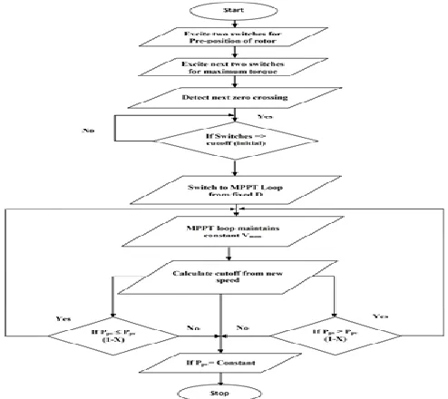
spurious detection of zero crossing instants of back-EMF. A sample and hold circuit is used for filtering the voltage spikes due to the conduction of the freewheeling diode, a low pass filter is used in the proposed control scheme. The advantages of using a low pass filter are twofold. First, it filters-out the voltage spikes due to the diode conduction and also the higher frequency voltage components due to the PWM operation. Second, the cut-off frequency of the filter can be designed to achieve the required phase-shift for forcing the currents after the zero-crossing detection. Thus, the zero-crossing instants of the back-EMFs ea, eb and ec are obtained. Initially, the back-EMF is zero when the rotor is at a standstill and the rotor position is also unknown. Hence, the rotor is pre-positioned by exciting any two phases of the PMSM motor. Later, a start-up sequence of phase commutation is implemented until the motor generates sufficient back-EMF.
2.2 MPPT Operation
For achieving the MPP operation, the DC link voltage and current, Vdc and Idc are sensed, which are used to measure the input power, as shown in Fig. 3. A Perturb and Observe (P&O) algorithm is used to achieve the MPP operation. The triggering instants are generated from the sensorless algorithm and the MPP voltage is given by the MPPT block, which is decided based on the available PV power Ppv Further, the duty ratio D is also obtained from the MPPT block and the pulse-width modulation (PWM) signals are generated. The output signals of the comparator and commutation blocks are inputs to an AND-gate, whose output signals are given to the upper switches SA+, SB+ and SC+. The lower switches SA−, SB− and SC− are triggered from the sensorless control block without PWM operation. Hence, only the upper switches are pulse width modulated while the lower switches are continuously ON. The sensorless commutation signals for the inverter switches based on the sensed line voltage difference and the type of zero crossing are given in Table-I. Hence, unlike in the existing literature, the system is able to perform both MPP operation and phase commutation using a single-stage three-phase inverter with only six switches. This eliminates the need of a dedicated dc-dc converter for MPP operation, thereby improving efficiency and reliability of the overall system.
3782 TABLE I
COMMUTATION SIGNALS
2.3 Design of DC-Link Capacitor
In a PMSM motor drive, the dc-link capacitor is designed considering the dominant sixth harmonic component on the dc side. Further, the fundamental frequency of the VSI output voltage is calculated for minimum operating speed of the PMSM motor. This ensures that the water pumping system operates even during minimum insolation levels. The calculated value of dc-link capacitance considering the current harmonics at minimum operating speed of the motor.
dc dc dc
V I C
min
6
(7)
where, Idc is the dc-link current, ωmin is the minimum operating speed in rad/s, and Vdc is the dc-link voltage ripple. From (7), the required value of the capacitance is calculated to be 201 µF, for ωmin of 62.83 rad/s.
2.4 Sizing of PV array
The solar irradiation of 1000 W/m2 is achieved under the standard test conditions (STC). The peak power rating of the PV array is decided considering the losses in the motor, inverter and deviations from the STC. The open circuit voltage of the PV array is chosen to be 320 V, with the array operating voltage between 170 to 260 V.
Fig.4. Flow chart of the sensorless control implementation with MPPT and LPF cut-off frequency calculation.
2.5 Design of the Digital Low-Pass Filter
The digital low-pass filter is used to filter-out both the voltage spikes during the free-wheeling period and the PWM components in line voltages. The filter cut-off frequency is decided based on the operating speed of the motor. For producing maximum torque, the zero-crossing instants of the back-EMFs should be delayed by 30 electrical degrees. Hence, for different operating speeds the cut-off frequency should be calculated accordingly. During the sensorless start-up, the cut-off frequency is decided based on the duty ratio D. Further, in the sensorless running mode it is decided according to the motor operating speed. The flow- chart for the implementation of the sensorless algorithm is shown in Fig. 4. The required phase shift (θLP F ) of 30 electrical degrees is obtained by the following equation of the low-pass filter,
) tan( c
LPF a f
(8)
3. SIMULATION RESULTS OF THE
SINGLE-STAGE SENSORLESS CONTROL SCHEME
WITH MPPT
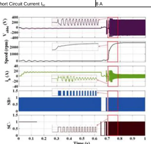
The proposed system and sensorless control scheme is simulated in the MATLAB/Simulink platform, and the results obtained are presented in this section. The values of the parameters considered for simulation are given in Table-II. The sensorless control of the motor is initialized by exciting phases B and C until 0.65 s as shown in Fig. 5, which pre- positions the rotor to a known position. Once the rotor aligns in this pre-determined position, the sensorless start-up sequence is implemented till 0.8 s. Initially, the duty ratio during the start-up is chosen to be low for reducing the starting currents. The phase current ib and line voltage difference waveforms Vab−bc during start-up are shown in Fig. 5. It can be observed from the figure that due to the use of a low-pass filter, the phase-current is delayed appropriately with respect to the back-EMF. Once the magnitude of the back-EMF is detectable i.e., after achieving sufficient speed, the sensorless mode is switched over from the start-up sequence to the running mode at the time instant of 0.8 s, as shown in Fig. 5. The speed increases steadily during the start-up until 0.8 s, where the rotor speed reaches steady state in the running mode, as shown in the figure. The developed torque is around 4.3 Nm.
TABLE II
PMSM MOTOR DRIVE PARAMETERS
Design Parameter Value
Rated Torque Td 4.2 Nm
Rated Power Pd 1.5 kW
Rated Speed Nr 2880 rpm
Poles Nm 10
Phase Inductance Lph 4 mH
Phase Resistance Rph 0.7 Ω
Torque Constant Kt 0.7 Nm/A
Voltage Constant Ke 74 V/krpm
3783 IJSTR©2020
Short Circuit Current Isc 8 A
Fig.5. Sensorless pre-position, start-up and transition to
running mode of the submersible PMSM motor obtained from simulation.
The filtered line voltage difference and back-EMF wave-forms in the running mode are shown in Fig. 6. It can be observed from the figure that despite the spurious zero crossings due to the freewheeling diode conduction, the zero crossing instants are correctly determined. Hence, the use of low-pass filter eliminates the voltage spikes due to the diode, filters the harmonic components due to the PWM and also gives an appropriate delay after the zero-crossing instant. Hence, the virtual hall-signals generated based on the sensorless algorithm successfully commutates the motor until it reaches its rated speed.
Fig.7.Response of the system for step changes in irradiation.
The effectiveness of MPP tracking along with the sensorless
control of the motor is simulated. The PV voltage Vpv , current ipv, power Ppv at an irradiation of 1000 W/m2 are shown in Fig. 7. The duty cycle D is initially chosen to be 0.1, to limit the starting current within the safety limits and thereafter increased during the steady state operation. The PV current ipv is 5.5 A, motor operating speed is 2845 rpm and developed torque is 4 Nm. At time t = 1 s, a step change in irradiation from 1000 W/m2 to 600 W/m2 is simulated. The response of the system for this step change in irradiation is shown in Fig. 7. It can be observed from the figure that the PV power, current, operating speed, torque and phase current have reduced due to the decrease in irradiation. However, the PV voltage is maintained at 260 V despite the step change in the insolation which proves the effectiveness of the MPPT operation. The motor operating speed is higher than 2140 rpm, which validates the successful pumping at reduced insolation levels. At time t =2 s, the irradiation is changed from 600 W/m2 to 800 W/m2 and the PV power, current, speed, torque and phase current are observed to increase correspondingly. Similarly, for lower irradiation levels the motor and pump speed is decided by appropriately varying the duty ratio D thereby allowing the system to operate in MPPT.
4.
PROTOTYPE
FABRICATION
AND
EXPERIMENTAL VALIDATION
A laboratory prototype of the deep bore-well submersible sensorless PMSM motor drive is fabricated. The 3-D schematic of the fabricated system is shown in Fig. 8. The diameter of the bore-well is 100 mm (4-inch) and hence the motor and controller enclosures are tubular in construction. The enclosure of the controller is coupled to the motor using the non-driving end flange. The system is designed to be submerged in the ground water level. Hence, both the motor and controller are hermetically sealed. Nitrile rubber based ―O-rings‖ are used to seal the interiors of the motor and controller, which are placed in the circular slots carved on the end-flanges. Stainless steel (SS) grade 304 is used for both the motor and controller frames and end-flanges.
Fig.8.3-D schematic diagram of the tubular submersible deep bore-well PMSM motor with the sensorless drive.
3784
(PCBs). The PCBs are designed to be circular in order to fit them inside the tubular controller frame. Three SS-304 based keys are designed to hold the PCBs in the frame with appropriate spacing between them. The power circuit with the IPM module is fixed at the end of the controller frame. The assembly of the keys along with the PCBs are placed in the key-way slots carved inside the controller frame.The IPM is mounted on PCB in the controller frame which acts as the heat sink and enables water cooling. An 18 A, 600V, 3 phase IGBT based small low-loss intelligent molded module (SLLIMM) IPM is used as a power module. It includes driver ICs for gate-signals and free-wheeling diodes. A Texas Instruments (TI) based floating point DSP, TMS320F28069 is used for implementing the control strategy. An LA-55P current sensor and a TL072CP general purpose Op-Amp based voltage sensor are used for implement-ing MPP operation. Three TL072CP Op-Amp based voltage sensors are used for sensing the motor line voltages. An LV-25S differential Op-Amp is used for obtaining the filtered line voltage differences. The PMSM motor drive parameters given in Table-II are considered for the experimental validation.
Fig.9.Experimental set-up of the submersible PMSM motor drive coupled to a dynamometer for loading.
Fig.10.Experimental waveforms of sensorless pre-position, start-up and transition to running mode of the submersible
PMSM motor.
The submersible PMSM motor is coupled to a dc generator
which is connected to a resistive load as shown in Fig. 9. The pump load is emulated by driving the motor and generator setup feeding the resistive load. Experimental tests are carried-out on the 1.5 kW, 2880 rpm spoke-type PMSM motor fed by a solar array simulator. The pre-positioning and sensorless start-up are shown in Fig. 10. It can be observed from the figure that the preposition interval lasts for a short duration of 3 s and later the sensorless start-up takes over. Initially the duty ratio D is fixed to be 0.1 in order to limit the starting current. After implementing the sensorless algorithm there is a smooth transition from the start-up mode to sensorless mode. The line voltages, Vab and Vbc and phase B current in the sensorless running mode are shown in Fig. 11. It can be observed that, the use of low-pass filter gives a desired phase shift and commutates the motor with an appropriate delay after detecting the back-EMF zero crossing.
Fig.11.Experimental waveforms of line voltages, gate pules and phase current in the sensorless running mode.
3785 IJSTR©2020
5. CONCLUSION
A single-stage sensorless control of a deep bore-well PV based submersible ferrite PM PMSM motor is presented. Bore-well pumps have poor ambience and thus hall-effect sensor
REFERENCES
[1]. J. X. Shen and K. J. Tseng, ―Analyses and compensation of rotor position detection error in sensorless PM brushless DC motor drives,‖ IEEE Trans. Energy Convers, vol. 18, no. 1, pp. 87–93, Mar 2003.
[2]. S. Wang and A. C. Lee, ―A 12-step sensorless drive for brushless DC motors based on back-EMF differences,‖ IEEE Trans. Energy Convers, vol. 30, no. 2, pp. 646– 654, June 2015.
[3]. Y. Zhou, D. Zhang, X. Chen, and Q. Lin, ―Sensorless direct torque control for saliency permanent magnet brushless dc motors,‖ IEEE Trans. Energy Convers, vol. 31, no. 2, pp. 446–454, June 2016.
[4]. R. Kumar and B. Singh, ―Solar PV powered PMSM motor drive for water pumping using cuk converter,‖ IET Electr. Power Appl, vol. 11, no. 2, pp. 222–232, 2017.
[5]. ―Solar PV array fed water pumping system using SEPIC converter based PMSM motor drive,‖ in Proc. Eighteenth National Power Systems Conf, Guwahati, Dec 2014, pp. 1–5.
[6]. ―Buck-boost converter fed PMSM motor drive for solar PV array based water pumping,‖ in Proc. IEEE Power Electronics, Drives and Energy Systems International Conf., Mumbai, Dec 2014, pp. 1–6.
[7]. G. N. A. Maranho, A. U. Brito, J. T. Pinho, J. K. S. Fonseca, A. M. Leal, and W. N. Macłdo, ―Experimental results of a fuzzy controlled variable-speed drive for photovoltaic pumping systems: A review,‖ IEEE Sensors J., vol. 16, no. 9, pp. 2854–2864, May 2016. [8]. S. A. K. M. Niapoor, S. Danyali, and M. B. B. Sharifian,
―PV power system based MPPT Z-source inverter to supply a sensorless PMSM motor,‖ in Proc. 1st Power Electronic Drive Systems Technologies Conf., Tehran, Feb 2010, pp. 111–116.
[9]. S. Jain, A. K. Thopukara, R. Karampuri, and V. T. Somasekhar, ―A single-stage photovoltaic system for a dual-inverter-fed open-end winding induction motor drive for pumping applications,‖ IEEE Trans. Power Electron., vol. 30, no. 9, pp. 4809–4818, Sept 2015. [10].S. Jain, R. Karampuri, and V. T. Somasekhar, ―An