95 | P a g e
SMART VEHICLE SECURITY SYSTEM USING
BIOMETRIC TECHNOLOGY
LOGESHKUMAR.D(1), BHARANITHARAN.S(2), SINGARAVEL.U(3),
RAMACHANDRAN.R(4).
1. B.E (ECE), Sengunthar Engineering College, India.
2.
B.E (ECE), Sengunthar Engineering College, India.
3. B.E (ECE), Sengunthar Engineering College, India.
4. B.E (ECE), Sengunthar Engineering College, India.
ABSTRACT:
Face Recognition concept is one of the successful and important applications of image analysis. It’s a holistic approach towards the technology and have potential applications in various areas such as Biometrics, Information society, Smart cards, Access control etc. A face recognition technology is used to automatically identify a person through a digital image. It is mainly used in security systems. The face recognition will directly capture information about the shapes of faces. The main advantage of facial recognition is it identifies each individual’s skin tone of a human face’s surface, like the curves of the eye hole, nose, and lips, etc. this technology may also be used in very dark condition. It can view the face in different angles to identify. Also this is use in vehicle security. The use of vehicle is must for everyone. At the same time, protection from theft is also very important. Prevention of vehicle theft can be done remotely by an authorized person. The purpose Embedded Car Security System captures the image using a camera which will be hidden in the dash board. Face Detection Algorithm is used to detect the face. A database is created by taking the pictures of all the family members. A minimum of ten photos of each family member is taken. This captured image is compared with the already present database using PCA algorithm. Once the captured face matches with the already present database a message is sent to the owner of the vehicle stating “Match Found”. Otherwise, if the captured face does not match with the database then the processor activates the GPS module and the GSM module. Using the GPS module the location of the vehicle is found out. This location is sent through the GSM module to the owner of the vehicle. Also along with the location, the image of the driver is sent through MMS to the owner
.
KEYWORDS:
Vehicle security, Face detection, Face recognition,Multimedia messaging service (MMS),
Authorization.
I.INTRODUCTION:
96 | P a g e
features. Sometimes these systems fail due to hacked password and encryption of decrypted data, but it is almost impossible to make replica of distinctive characteristics. Biometric systems are modern and use techniques like fingerprint recognition, iris recognition and face recognition. Of these face recognition and detection systems are more sophisticated, easy to deploy and people can be identified without their knowledge. Some advantages of facial recognition method for vehicle security application are:-
1.More convenient, sensed as soon as one is seated in position. 2.Low cost and a better approach to be used with existing methods. 3.Requires no active part of the user.
In vehicle security system, the objective is to prevent the theft of vehicle and ensure safety of vehicle by avoiding the means of theft. One level of ensuring authentication of driving is through face recognition system that authenticates a user being an authorized person to have access to the ignition system. The microprocessor based control system fixed inside the vehicle uses GPS receiver, GSM modem and captures image from the camera on detection of person in the parked vehicle. Face is detected and recognized using algorithm overcoming the pose and illumination constraints. The recognized image is compared with the authorized image of users in the database. If matched, the system allows operating the vehicle. If not matched, it sends MMS of face and GPS values to the owner. Shihab A.Hameedetal, (2011) in their work focused on the MMS and database technology with good response time. This helps the owner in making decision about the control of vehicle. The owner decides and commands the system to prevent the access of the vehicle or to allow the person to operate the vehicle.
II. EXISTING METHOD:
The existing method consists of following features there are: 1. Door lock system in finger print method.
2. Tracking system. 3. Alarm system. 4. Monitor system.
III. PROPOSED METHOD:
In proposed method we are adding following features there are: 1. Door lock system in face recognition method.
2. Fuel lock system. 3. Alert system.
4. AC monitoring system. 5. Alarm and tracking system.
IV. METHODOLOGY:
97 | P a g e
algorithm for authentication. The entire security system comprising each component is shown in Fig. 1. Bagavathyetal, (2011) realized the importance of using ARM processor in real time applications. Hence ARM 7 microprocessor is used as the control unit in the system. The passive infrared sensor attached to the seat of the driver activates the hidden camera fixed inside the vehicle through the ARM 7 microprocessor control of the microcomputer once the intruder enters the car. The camera acquires the image of the person inside the car fixed in an appropriate position in front of the driver seat. Once the image of the person is acquired, the system now tries to detect the face.
1.BLOCK DIAGRAM:
2. Image processing:
The microcomputer which contains the image processing unit embedded within it performs the face detection and authorizes the person. The processing of image involves two parts, face detection and face recognition. 3.1.1 Face Detection The acquired image is processed to detect the face using the Viola Jones algorithm (Viola and Jones, 2002) which effectively uses the cascade object detection. The cascade detector detects the face of the acquired image and the face region is extracted. The authentication based security system has the database which stores the face images of the authorized persons under different environments. The face images are enhanced by normalizing them to remove the unwanted information due to illumination constraints while acquiring the image and are stored in the database. Now the task of face recognition must be performed with the detected faces.
3. Face Recognition:
98 | P a g e
4. Face Detection algorithm:
Object detection and tracking are important in many computer vision applications including activity recognition, automotive safety, and surveillance. In this we developed a simple face tracking system by dividing the tracking problem into three separate problems: 1.Detect a face to track 2.Identify facial features to track 3.Track the face. Before we begin tracking a face, we need to first detect it. Use the Cascade Object Detector to detect the location of a face in a frame. The cascade object detector uses the Viola-Jones detection algorithm and a trained classification model for detection. By default, the detector is configured to detect faces, but it can be configured for other object types. We can use the cascade object detector to track a face across successive frames. However, when the face tilts or the person turns their head, you may lose tracking. This limitation is due to the type of trained classification model used for detection. To avoid this issue, and because performing face detection for every video frame is computationally intensive, this uses a simple facial feature for tracking. Once the face is located, the next step is to identify a feature that will help you track the face. For example, we can use the shape, texture, or color. Choose a feature that is unique to the object and remains invariant even when the object moves. In this paper, we use skin tone as the feature to track. The skin tone provides a good deal of contrast between the face and the background and does not change as the face rotates or moves. With the skin tone selected as the feature to track, we can now use the Histogram Based Tracker for tracking. The histogram based tracker uses the CAM-Shift algorithm, which provides the capability to track an object using a histogram of pixel values. In this the Hue channel pixels are extracted from the nose region of the detected face. These pixels are used to initialize the histogram for the tracker. This paper tracks the object over successive video frames using this histogram.
V. HARDWARE DESCRIPTION:
1.STM32 – ARM CORTEX M3
:
STM32 is a family of 32-bit microcontroller integrated circuits by STMicroelectronics. The STM32 chips are grouped into related series that are based around the same 32-bit ARM processor core, such as the Cortex-M7F, Cortex-M4F, Cortex-M3, Cortex-M0+, or Cortex-M0. Internally, each microcontroller consists of the processor core, static RAM memory, flash memory, debugging interface, and various peripherals.
The STM32 is a family of microcontroller ICs based on the 32-bit RISC ARM M7F, M4F, Cortex-M3, Cortex-M0+, and Cortex-M0 cores.[1] STMicroelectronics licenses the ARM Processor IP from ARM Holdings. The ARM core designs have numerous configurable options, and ST chooses the individual configuration to use for each design. ST attaches their own peripherals to the core before converting the design into a silicon die. The following tables summarize the STM32 microcontroller families.
General information
• Description of the history and present state of the STM32 line. ARM Cortex-M series etc. • Introduction and pointers to ARM Cortex-M docs and other good books on the subject.
99 | P a g e
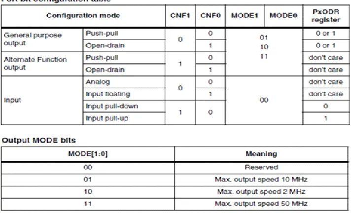
In any microcontroller there is at least one general purpose input-output port. STM32 is a not different breed and as expected it also has several GPIO ports. These ports are usually named GPIOA, GPIOB, etc. but unlike most 8/16-bit micros these ports are 16 8/16-bit wide. Thus, in general, every port has 16 IO pins. Port pins have several modes of operation and this is what that makes them both robust and complex at first. In development boards the IO port pin naming is cut short and so we’ll find PA0, PB12, etc. instead of GPIOA0, GPIOB12, etc. Even in the reference manuals this short naming is used widely. In the end every I/O pin is general purpose in nature.
Fig 1.1: STM 32 Port pin Configuration
VI. SOFTWARE DESCRIPTION:
An Overview of Embedded SystemsMPLAB IDE is a software program that runs on a PC to develop applications for Microchip microcontrollers. It is called an Integrated Development Environment, or IDE, because it provides a single integrated "environment" to develop code for embedded microcontrollers. Experienced embedded systems designers may want to skip ahead to Components of MPLAB IDE. It is also recommended that MPLAB IDE On-line Help and MPLAB IDE Updates and Version Numbering be reviewed. The rest of this chapter briefly explains embedded systems development and how MPLAB IDE is used.
•
Description of an "Embedded System"•
Differences Between an Embedded Controller and a PC•
Components of a Microcontroller•
Implementing an Embedded System Design with MPLAB IDEDescription of an "Embedded System"
100 | P a g e
same chip to make a small control module requiring few other external devices. This single device can then be embedded into other electronic and mechanical devices for low-cost digital control.
Differences Between an Embedded Controller and a PC
The main difference between an embedded controller and a PC is that the embedded controller is dedicated to one specific task or set of tasks. A PC is designed to run many different types of programs and to connect to many different external devices. An embedded controller has a single program and, as a result, can be made cheaply to include just enough computing power and hardware to perform that dedicated task. A PC has a relatively expensive generalized central processing unit (CPU) at its heart with many other external devices (memory, disk drives, video controllers, network interface circuits, etc.). An embedded system has a low-cost microcontroller unit (MCU) for its intelligence, with many peripheral circuits on the same chip, and with relatively few external devices. Often, an embedded system is an invisible part, or sub-module of another product, such as a cordless drill, refrigerator or garage door opener. The controller in these products does a tiny portion of the function of the whole device. The controller adds low-cost intelligence to some of the critical sub-systems in these devices.
An example of an embedded system is a smoke detector. Its function is to evaluate signals from a sensor and sound an alarm if the signals indicate the presence of smoke. A small program in the smoke detector either runs in an infinite loop, sampling the signal from the smoke sensor, or lies dormant in a low-power "sleep" mode, being awakened by a signal from the sensor. The program then sounds the alarm. The program would possibly have a few other functions, such as a user test function, and a low battery alert. While a PC with a sensor and audio output could be programmed to do the same function, it would not be a cost-effective solution (nor would it run on a nine-volt battery, unattended for years!). Embedded designs use inexpensive microcontrollers to put intelligence into the everyday things in our environment, such as smoke detectors, cameras, cell phones, appliances, automobiles, smart cards and security systems
Components of a Microcontroller
The PICmicro MCU has program memory for the firmware, or coded instructions, to run a program. It also has "file register" memory for storage of variables that the program will need for computation or temporary storage. It also has a number of peripheral device circuits on the same chip. Some peripheral devices are called I/O ports. I/O ports are pins on the microcontroller that can be driven high or low to send signals, blink lights, drive speakers - just about anything that can be sent through a wire. Often these pins are bidirectional and can also be configured as inputs allowing the program to respond to an external switch, sensor or to communicate with some external device.
Implementing an Embedded System Design with MPLAB IDE
A development system for embedded controllers is a system of programs running on a desktop PC to help write, edit, debug and program code - the intelligence of embedded systems applications - into a microcontroller. MPLAB IDE runs on a PC and contains all the components needed to design and deploy embedded systems applications.
The typical tasks for developing an embedded controller application are:
101 | P a g e
translatable into machine code, or a compiler that allows a more natural language for creating programs, should be used to write and edit code. Assemblers and compilers help make the code understandable, allowing function labels to identify code routines with variables that have names associated with their use, and with constructs that help organize the code in a maintainable structure.
• Compile, assemble and link the software using the assembler and/or compiler and linker to convert your code into "ones and zeroes" - machine code for the PICmicro MCUs. This machine code will eventually become the firmware (the code programmed into the microcontroller).
• Test your code. Usually a complex program does not work exactly the way imagined, and "bugs" need to be removed from the design to get proper results. The debugger allows you to see the "ones and zeroes" execute, related to the source code you wrote, with the symbols and function names from your program. Debugging allows you to experiment with your code to see the value of variables at various points in the program, and to do "what if" checks, changing variable values and stepping through routines.
• "Burn" the code into a microcontroller and verify that it executes correctly in the finished application.
Of course, each of these steps can be quite complex. The important thing is to concentrate on the details of your own design, while relying upon MPLAB IDE and its components to get through each step without continuously encountering new learning curves.
Step 1 is driven by the designer, although MPLAB IDE can help in modeling circuits and code so that crucial design decisions can be made.
MPLAB IDE really helps with steps 2 through 4. Its Programmer's Editor helps write correct code with the language tools of choice. The editor is aware of the assembler and compiler programming constructs and automatically "color-keys" the source code to help ensure it is syntactically correct. The Project Manager enables you to organize the various files used in your application: source files, processor description header files and library files. When the code is built, you can control how rigorously code will be optimized for size or speed by the compiler and where individual variables and program data will be programmed into the device. You can also specify a "memory model" in order to make the best use of the microcontroller's memory for your application. If the language tools run into errors when building the application, the offending line is shown and can be "double clicked" to go to the corresponding source file for immediate editing. After editing, press the "build" button to try again. Often this write-compile-fix loop is done many times for complex code as the sub-sections are written and tested. MPLAB IDE goes through this loop with maximum speed, allowing you to get on to the next step.
Once the code builds with no errors, it needs to be tested. MPLAB IDE has components called "debuggers" and free software simulators for all PICmicro MCU and dsPIC DSC devices to help test the code. Even if the hardware is not yet finished, you can begin testing the code with the simulator, a software program that simulates the execution of the microcontroller. The simulator can accept a simulated input (stimulus), in order to model how the firmware responds to external signals. The simulator can measure code execution time, single step through code to watch variables and peripherals, and trace the code to generate a detailed record of how the program ran.
102 | P a g e
microcontroller in the target using a high-speed probe to give you full control over the hardware in your design. The MPLAB ICD 2 uses special circuitry built into many Microchip MCUs with Flash program memory and can "see into" the target microcontrollers program and data memory. The MPLAB ICD 2 can stop and start program execution, allowing you to test the code with the microcontroller in place on the application.
After the application is running correctly, you can program a microcontroller with one of Microchip's device programmers, such as PICSTART® Plus or MPLAB PM3. These programmers verify that the finished code will run as designed. MPLAB IDE supports most PIC micro MCUs and every ds PIC Digital Signal Controller.
A Basic Tutorial for MPLAB IDE
MPLAB Integrated Development Environment (IDE) is a comprehensive editor, project manager and design desktop for application development of embedded designs using Microchip PIC micro MCUs and dsPIC DSCs.
The initial use of MPLAB IDE is covered here. How to make projects, edit code and test an application will be the subject of a short tutorial. By going through the tutorial, the basic concepts of the Project Manager, Editor and Debugger can be quickly learned. The complete feature set of MPLAB IDE is covered in later chapters.
This section details the installation and uninstall of MPLAB IDE. It is followed by a simple step-by-step tutorial that creates a project and explains the elementary debug capabilities of MPLAB IDE. Someone unfamiliar with MPLAB IDE will get a basic understanding of using the system to develop an application. No previous knowledge is assumed, and comprehensive technical details of MPLAB IDE and its components are omitted in order to present the basic framework for using MPLAB IDE.
Components of MPLAB IDE
The MPLAB IDE has both built-in components and plug-in modules to configure the system for a variety of software and hardware tools.
•
MPLAB IDE Built-In Components•
Additional Optional Components for MPLAB IDEMPLAB IDE Built-In Components
The built-in components consist of: • Project Manager
The project manager provides integration and communication between the IDE and the language tools. • Editor
The editor is a full-featured programmer's text editor that also serves as a window into the debugger. • Assembler/Linker and Language Tools
The assembler can be used stand-alone to assemble a single file, or can be used with the linker to build a project from separate source files, libraries and recompiled objects. The linker is responsible for positioning the compiled code into memory areas of the target microcontroller.
• Debugger
103 | P a g e
• Execution Engines
There are software simulators in MPLAB IDE for all PICmicro MCU and dsPIC DSC devices. These simulators use the PC to simulate the instructions and some peripheral functions of the PICmicro MCU and dsPIC DSC devices. Optional in-circuit emulators and in-circuit debuggers are also available to test code as it runs in the applications hardware.
Additional Optional Components for MPLAB IDE
Optional components can be purchased and added to the MPLAB IDE: • Compiler Language Tools
MPLAB C18 and MPLAB C30 C compilers from Microchip provide fully integrated, optimized code. Along with compilers from HI-TECH, IAR, microEngineering Labs, CCS and Byte Craft, they are invoked by the MPLAB IDE project manager to compile code that is automatically loaded into the target debugger for instant testing and verification.
• Programmers
PICSTART Plus, PICkit 1 and 2, PRO MATE II, MPLAB PM3 as well as MPLAB ICD 2 can program code into target devices. MPLAB IDE offers full control over programming both code and data, as well as the Configuration bits to set the various operating modes of the target microcontrollers or digital signal controllers.
• In-Circuit Emulators
MPLAB ICE 2000 and MPLAB ICE 4000 are full-featured emulators for the PICmicro MCU and dsPIC DSC devices. They connect to the PC via I/O ports and allow full control over the operation of microcontroller in the target applications.
• In-Circuit Debugger
MPLAB ICD 2 provides an economic alternative to an emulator. By using some of the on-chip resources, MPLAB ICD 2 can download code into a target microcontroller inserted in the application, set breakpoints, single step and monitor registers and variables.
MPLAB IDE Features and Installation
MPLAB IDE is a Windows® Operating System (OS) based Integrated Development Environment for the PIC micro MCU families and the ds PIC Digital Signal Controllers. The MPLAB IDE provides the ability to:
• Create and edit source code using the built-in editor. • Assemble, compile and link source code.
• Debug the executable logic by watching program flow with the built-in simulator or in real time with in-circuit emulators or in-circuit debuggers.
• Make timing measurements with the simulator or emulator. • View variables in Watch windows.
104 | P a g e
VII. CONCLUSION:
From this we implement theft control techniques that can provide the important functions required by advanced intelligent Car Security, to avoid vehicle theft and protect the usage of unauthenticated users. A secured and safety environment system for automobile users and also the key points for the investigators can be easily found out with the hijackers image. We can predict the theft by using this system in our day today life. This project will help us to reduce the complexity and improve security, also much cheaper and smarter than traditional ones. Experiment results show that it takes about 6seconds to detect one 320*480 color jpeg image by software which is running on Android board. It seems to be too long to be used in real-time detection,By introducing the mobile app with good GUI will heps to the operation of the proposed system more Convenient.
Face recognition is a both challenging and important recognition technique. Among all the biometric techniques, face recognition approach possesses one great advantage, which is its user friendliness. This paper proposes the image recognition techniques that can provide the important functions by advanced intelligent automobile security, to avoid vehicle theft and protect the use of unauthenticated users. Secured and safety environment system for automobile users and also key points for the investigators can easily find out the hijacked image. From this we can predict the theft by using this in our daily life. This system mainly helps to reduce the complexity and improve security, also much cheaper and smarter than traditional one’s.
REFERENCES
[1]. Motor theft statistics as given http://en.wikipedia.org/wiki/Motor_vehicle_theft#
[2]. Sukeerti Singh and Ayushi Mhalan, Vehicle Theft Alert System using GSM, Int. Journal of Engineering Science and Technology (IJEST), May 2013
[3]. M.Sunitha, V.Vinay Ku mar and G. Raghu, Embedded Car Security System, Int. Journal of Engineering Development and Research (IJEDR), 2012
[4]. Z. M. Win and M. M. Sein, Fingerprint recognition system for low quality images, presented at the SICE Annual Conference, Waseda University, Tokyo, Japan, Sep. 13-18, 2011.
[5]. Upendran Rajendran and Albert Joe Francis, Anti Theft Control System Design Using Embedded System, Proc. IEEE, vol. 85, page no. 239- 242, 2011
[6]. Vikram Kulkarni and G. Narsimhulu, A Low cost Extended Embedded Smart Car Security System on Face Detection and Continuous Video Monitoring System, Int. Journal of Engineering Science and Advanced Technology (IJESAT), May 2012