FLOW VISUALIZATION AROUND A
NON-CIRCULAR TUBE
A. Nouri - Borujerdi*
Department of Mechanical Engineering, Sharif University of Technology Tehran, Iran, [email protected]
A. M. Lavasani
Department of Mechanical Engineering, Science and Research Branch Islamic Azad University, Tehran, Iran
*Corresponding Author
(Received: December 30, 2004 – Accepted in Revised Form: November 2, 2006)
Abstract The flow behavior around a cam shaped tube in a cross flow has been investigated experimentally using flow visualization and pressure distribution measurements. The range of attack angle and Reynolds number based on an equivalent circular diameter are within 0≤α≤360o and
4 eq
4 Re 3.4 10
10
2× 〈 〈 × , respectively. The pressure drag features are clarified in relation to the flow behavior around the tube. It is found that the highest pressure drag coefficient occurs at α = 90° and 270°over the whole range of Reynolds number. Results show that the pressure drag coefficient of the cam - shaped tube is lower than that of a circular tube with the same surface area for more of the attack angles.
Key Words Experiment, Visualization, Pressure Drag, Cross Flow, Non-Circular Tube
ﻩﺪﻴﮑﭼ
ﯼﺯﺎـﺳﺭﺎﮑـﺷﺁﻭﺭﺎﺸـﻓﻊﻳﺯﻮﺗﯼﺮﻴﮔﻩﺯﺍﺪﻧﺍﺎﺑﯽﺿﺮﻋﻥﺎﻳﺮﺟﺭﺩﻞﮑﺷﯽﮑﻣﺍﺩﺎﺑﻪﻟﻮﻟﮏﻳﻑﺍﺮﻃﺍﻥﺎﻳﺮﺟ ﻝﺎﻴﺳﺮﻴﺴﻣ ،
ﻲﺳﺭﺮﺑ
ﺖـﺳﺍﻩﺪـﺷﻲـﺑﺮﺠﺗ
. ﺩﺪـﻋﻭﻪـﻠﻤﺣﻪـﻳﻭﺍﺯ
ﺩﻭﺪـﺤﻣﺭﺩﺐـﻴﺗﺮﺗﻪـﺑﺯﺪـﻟﻮﻨﻳﺭ
o
360 α 0≤ ≤
ﻭ 4 eq 4 Re 3.4 10 10
2× 〈 〈 ×
. ﺪﻧﺭﺍﺩﺭﺍﺮﻗ
.
ﺩﺎﻌﻣﺮﻄﻗﺱﺎﺳﺍﺮﺑﺯﺪﻟﻮﻨﻳﺭﺩﺪﻋ
ﺖﺳﺍﻩﺪﺷﻒﻳﺮﻌﺗﯼﺍﻩﺮﻳﺍﺩﻝ
. ﯼﺭﺎﺸﻓﮒﺭﺩ
ﺖﺳﺍﻩﺪﺷﺺﺨﺸﻣﻪﻟﻮﻟﻑﺍﺮﻃﺍﻥﺎﻳﺮﺟﺭﺎﺘﻓﺭﻪﺑﻪﺟﻮﺗﺎﺑ
.
ﻲﻣﻥﺎﺸﻧﺞﻳﺎﺘﻧ ﻪﻛﺪﻫﺩ
ﺭﺩﯼﺭﺎﺸـﻓﮒﺭﺩﺐﻳﺮﺿﻦﻳﺮﺘﺸﻴﺑ
ﯼﺎﻳﺍﻭﺯﻪﺑﻁﻮﺑﺮﻣﺶﻳﺎﻣﺯﺁﺯﺪﻟﻮﻨﻳﺭﺩﻭﺪﺤﻣ
°
۹۰
α =
ﻭ
°
۲۷۰ ﯽﻣ ﺪﺷﺎﺑ
. ﺐﻳﺮـﺿ،ﻪـﻠﻤﺣﯼﺎﻳﺍﻭﺯﺮﺜﮐﺍﺭﺩﻦﻴﻨﭽﻤﻫ
ﻳﺯﺍﺮﺘﻤﮐﯽﮑﻣﺍﺩﺎﺑﻪﻟﻮﻟﯼﺭﺎﺸﻓﮒﺭﺩ ﺖﺳﺍﻥﺎﺴﮑﻳﻲﺒﻧﺎﺟﺢﻄﺳﺎﺑﯼﻭﺮﻳﺍﺩﻪﻟﻮﻟﮏ
.
1. INTRODUCTION
The exploitations of high performance heat exchangers for saving and making effective use of energy is a very important and urgent problem. Among many types of heat exchangers, those constructed of non - circular tubes have been used in many industries. Major objectives in the design of these heat exchangers could be reduction of pressure drop and fouling for a given amount of heat transferred.
Ota et al. [1-2] experimentally investigated the thermal performance of a single elliptical cylinder
with a major to minor axes ratio of 2 and 3 in a flow of air having Reynolds numbers of 5000 < Rec < 90000 with angles of attack 0 < α < 90°. Re
c is the
Reynolds number based on the major axis c. For air flow parallel to the major axis, they found that the Nusselt number of the elliptical cylinder is higher than that of a circular cylinder from an empirical correlation.
axes ratio was 3.97. They showed that an exchanger with oval - shaped tubes has smaller frontal area on the shell-side compared to those with circular tubes.
Prasad et al. [4] reported heat transfer and pressure drop from an airfoil in cross flow. Their aerofoil test section was the NACA - 0024 and they concluded that this shape gives lower values of
C
f/
St
compared to the circular tube.Kondjoyan and Daudin [5] experimentally studied the effect of variation in the free stream turbulence intensity from 1.5% to 40% on the heat transfer from a circular cylinder and an elliptical cylinder with an axes ratio 4 for Reynolds numbers between
3 10
×
3<
Re
D< ×
4 10
4.Re
D is based on the diameter of an equivalent circular cylinder for an elliptical cylinder. Their conclusion is that the turbulence intensity effect is as important as the air velocity effect. They indicated that the Nusselt number for the elliptical cylinder is about 14% lower than that for the equivalent circular cylinder. Salazar et al. [6] measured heat transfer from a bank of elliptical tubes in cross-flow. The elliptical tube axes ratios were 1.054, 1.26, and 1.44. The characteristic length in Re and Nu for the elliptical tube is assumed to be equal to the minor axis. The results indicate that correlations of circular tubes are slightly higher than the measurements of the elliptical tubes.Badr [7] reported the forced convection heat transfer from an isothermal elliptic tube placed in a uniform air stream. In this study, the Reynolds number range was 20 < Re <500 and angles of inclination was 0° < α < 90°. The elliptical tube axes ratio varied between 0.4 and 0.9. His results show that the rate of heat transfer reaches its maximum value at α = 0° while the minimum occurs at α = 90°.
For evaporative cooled heat exchangers, Hasan and Sirén [8] showed that wet oval tube bundles have a better combined thermo hydraulic performance than corresponding circular tubes. Tiwari et al. [9] reported a three - dimensional computational study of forced convection heat transfer to determine the flow structure and heat transfer in a rectangular channel with a built - in oval tube and delta wing type vortex generators in various configurations. Their results indicate that vortex generators in conjunction with the oval
tubes show definite promise for improving fin tube heat exchangers.
Matos et al. [10] studied the numerical and experimental heat transfer rate between staggered arrangements of circular and elliptic of finned tube bundles and external flow. They have reported that the optimal elliptic arrangement exhibits a heat transfer gain of up to 19% compared to the optimal circular tube arrangement. The results illustrate that the heat transfer gain and the relative total mass reduction of up to 32% shows that the elliptical arrangement has the potential to deliver considerably higher global performance and lower costs.
Bouris et al. [11] proposed a tube cross-section with a parabolic upstream shape and a semi-circular one downstream. They carried out experimental and numerical simulations on the novel tube bundles heat exchanger for studying the thermal, hydraulic and fouling characteristics. Their results indicate that heat transfer increases with 75% lower in deposition rate and also 40% lower in pressure drop.
In the previous [4] and recent [11] studies, heat exchangers with non - circular cross sections similar to cam shaped tubes were employed to increase thermo hydraulic performance and reduce fouling. But, in this study, the flow visualization and pressure coefficient around a single cam shaped tube at 0≤α ≤360o have been
investigated experimentally.
2. EXPERIMENTAL APPARATUS
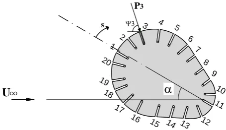
The test tube cross section comprises of two circles with diameters of d and D and a distance of l between their centers, (Figure 2). The tube is made of commercial copper plate with 0.3 mm thickness and a length of 120 mm. Three tubes were tested to investigate the effect of tube dimensions on the flow characteristics. The
dimensions of each tube are given in Table 1. The surface of each tube is covered with 20 holes (1 mm in diameter) drilled to measure the static pressure on the surface.
In order to clarify variations of the flow characteristics, the angle of attack is varies in the range of 0≤α ≤360o. The term α is the angle
between the major axis of the cam shaped tube with the upstream flow direction. The angle of attack measures the positive values on a clockwise rotation. The tunnel blockage ratio is maximum at α=90o and varies in the range of
0.09 to 0.27 for tube No. 1 to No. 3, respectively. In the present work, however, no correction is made for the tunnel wall effect upon the flow characteristics. A pitot static tube measures the velocity distribution around the tube. Also, a controlling variable speed motor was employed to measure the air velocity in the front of the test section between a range of 12.5 to 21.5 m/s.
3. MEASUREMENT
UNCERTAINTIES
To estimate the pressure drag of the cam shaped tube compared to that of a circular tube, it is important to select an appropriate reference length. This reference length can be the diameter of an equivalent circular tube, Deq, whose circumferential length is equal to that of the cam - shaped tube. Ratios of L/Deq for the three test tubes are 4.85, 3.36 and 2.03 and their effects on pressure drag coefficient are 38.3 %, 39.7 % and 43.3 %, respectively [12]. However, the ratio of L/Deq > 4 has little effect on heat transfer, so its effect on the second and third tubes is 4-6% and 6-10% respectively within 1.5 × 10⁴ <
Re
eq < 4.8 × 10⁴, [13].The pressure drag coefficient is determined experimentally through pressure distribution around the cam shaped - tube as:
⎪⎭ ⎪ ⎬ ⎫ ⎪⎩ ⎪ ⎨ ⎧ Δ ψ = ψ =
∫
∑
= 20 1 i i i i , p eq p eqD D C Cos S
1 ds cos C D 1
C (1)
Where ψi is the angle between the normal and free
α
D
d l
1 -B e ll M o u th 2 -H o n e yco m b 3 -T u b e 4 -F a n
4 3
2
A ir
Figure 1. A suction type subsonic wind tunnel.
s Ψ3
P3
α
U 20 19 18 1716 15 14 13 12 11 10 9 8 7 6 5 4 3 2 1
Figure 2. Schematic diagram of a cam shaped tube.
TABLE 2. Dimensions of three Test Cam - Shaped Tubes.
Tube No. d [mm] l [mm] D [mm] P [mm] L [mm]
Deq= P/π
[mm]
1 12 11 22 77.7 120 24.7
2 12 29 22 112.2 120 35.7
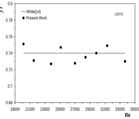
0.68 0.7 0.72 0.74 0.76 0.78 0.8
19000 21000 23000 25000 27000 29000 31000 33000 35000 Re
CD White[14]
Present Work L/D=5
Figure 3. Drag coefficient of a circular tube in cross flow.
stream direction at each hole location. Its value changes from one hole to another, (Figure 2). S measures the distance on the tube perimeter from the leading edge. The difference ΔSi belongs to each hole and represents a segment line on the tube perimeter.
The pressure coefficient is defined as follows:
2 i i , p U 2 1 P P C ∞ ∞ ρ −
= (2)
i
P and P∞ are the pressures of each hole and free stream respectively.
The measurement error of the tube pressure drag coefficient can easily be obtained by differentiation of Equation 1 and the final result will be as follows.
D
D) C
C ( = Δ 5 . 0 20 1 i 2 i i 2 i i 2 i, p i, p 2 eq eq S ) S ( Cotg ) ( C ) C ( D ) D ( ⎪⎭ ⎪ ⎬ ⎫ ⎪⎩ ⎪ ⎨ ⎧ ⎥ ⎥ ⎦ ⎤ ⎢ ⎢ ⎣ ⎡ ⎟⎟ ⎠ ⎞ ⎜⎜ ⎝
⎛ ΔΔ
+ ⎟⎟ ⎠ ⎞ ⎜⎜ ⎝ ⎛ ψ ψ Δ + ⎟ ⎟ ⎠ ⎞ ⎜ ⎜ ⎝ ⎛ Δ + ⎟ ⎟ ⎠ ⎞ ⎜ ⎜ ⎝ ⎛ Δ
∑
= (3) Where Δ(Deq) denotes a measurement error of the equivalent diameter with a value of aboutm 0005 . 0
± and making Δ(Deq)/Deq=2% for tube No.1. Δ(Cpi,), Δ(ψi) and Δ(ΔSi) are respectively the measurement errors of the pressure coefficient, angle of ψi and length on the tube perimeter.
The error of the pressure coefficient can be obtained by: 5 . 0 2 2 a 2 i, p i, p U U 2 P P P C ) C ( ⎥ ⎥ ⎦ ⎤ ⎢ ⎢ ⎣ ⎡ ⎟ ⎠ ⎞ ⎜ ⎝ ⎛ Δ + ⎟⎟ ⎠ ⎞ ⎜⎜ ⎝ ⎛ ρ ρ Δ + ⎟⎟ ⎠ ⎞ ⎜⎜ ⎝ ⎛ − Δ = Δ ∞
(4)
Its value is about 83 to 10% of . Cpi, for different velocities. The density of the air is a function of its temperature and can be obtained by the air physical properties [14] through:
) T ( T d d ) ( a a a a Δ ρ = ρ
Δ
(5)
Using the physical properties of air, the density gradient with respect to the temperature is easily obtained about 030. % of ρa. Δ(U) is about ±0.01 making that Δ(U)/U to be about 040. to 0.07 %. Substituting the above mentioned errors into Equation 3, the pressure drag coefficient uncertainty for tube No.1 is about 14.4 to 15.7 % in the range of 0≤α≤360o.
4. RESULTS AND DISCUSSION
Before testing the cam shaped-tube, a single circular tube with a diameter of 2.47 cm and length of 12.5 cm is tested to verify the data taking process and to check the related equipment setup. Figure 3 compares the present results with the results of White [12]. The difference between the present results and that of curve fit formula by White is about 1-2 percent.
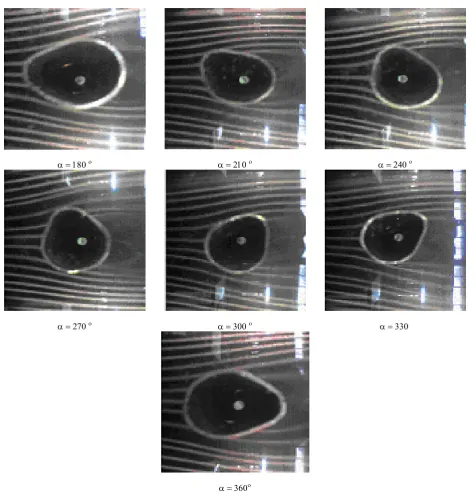
It can, therefore, be concluded that the set up can be used for flow visualization and measuring the pressure drag from a cam shaped tube. Representative examples of the flow visualization around tube No.1 at 180≤α≤360o are demonstrated
α = 180 ο α = 210 ο α = 240 ο
α = 270 ο α = 300 ο α = 330
α = 360ο
Figure 4. Flow visualization around a cam shaped tube for l D/ = 0.5: (a) α=180ο, (b) α = 210ο, (c) α = 240ο, (d) α=270ο
(e) α = 300ο, (f) α = 330οand (g) α = 360ο.
of the attack angle brings about a decrease of the flow velocity oncoming to the upstream surface of the tube. Furthermore, the wake region is relatively small and a transversal motion of the fluid may be
out frequently by the fluid entrained from the main flow.
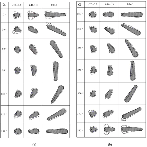
Figure 5 compares pressure distributions around three cam shaped tubes for different l/D and
0 ≤ α ≤ 360° at U = 15 m/s. The positive and negative pressure areas vary with the attack angle. The flow and heat transfer characteristics of the cam shaped tube are closely related to boundary
α
α
270 °
240 °
210 °
0 °
/D=0.5 /D=1.3 /D=3
30 °
60 °
90 °
120 °
150 °
180 ° 360 °
330 °
300 °
/D=3 /D=1.3
/D=0.5
180 °
(a) (b)
Figure 5. Pressure distribution around three cam shaped tubes for
o
360
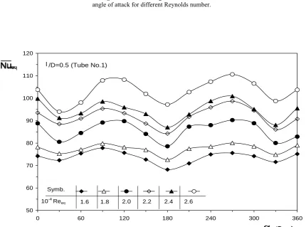
layer separation [15] and varies with the attack angle. Variation of the CD and Nueq with α for tube No.1 are shown in Figures 6 and 7. The drag coefficient curve is repeated every other 150º. The minimum drag coefficient and Nusselt number belong to α = 30°and α = 330°. As mentioned previously, a decrease in the oncoming flow velocity to the upstream surface brings about a relatively low value of drag coefficients and Nusselt number. On the other hand, CD and Nueq at α = 90°and α = 270° are highest over the whole Reynolds number range examined in the present work. During large angle attacks, the pressure inside the separated flow region is very low. Such a low pressure and large wake downstream of the tube may bring about a violent motion of fluid and a very high drag coefficient occurs as mentioned before. It is to be noted that the present value of CD and Nueq is based upon the equivalent diameter as the reference length.
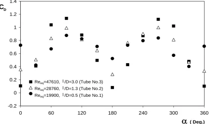
The flow characteristic of the cam shaped tube varies with d/D and l/D ratios. The effect of l/D ratio on the drag coefficient for the same d/D is studied against attack angle for U = 15 m/s. Variations of this coefficient with α for three cam shaped tubes are shown in Figure 8. The value of CD for l/D = 3 at α = 0, 180 and 360° is very low
compared with the other tubes. As shown in the figure, at angles in which the tube is horizontal (α = 0, 180 and 360°), the drag coefficient of more narrow tubes decreases but with increase in angle of attack the drag coefficient increases. So that at α = 0, 180 and 360° the drag coefficient
of the tube for l/D = 0.5 is about 2 and 6.5 times of this coefficient for tubes with l/D = 1.3 and l/D = 3. But at α = 90 and 270° these ratios are
0.74 and 0.85 respectively.
The corresponding drag coefficient values of the circular tubes, having the same circumferential length as cam shaped tubes (l/D = 0.5, 1.3 and 3) over the whole Reynolds number range examined in this work, are CD = 0.74, 0.72 and 0.68 [12],
respectively. So it is possible to compare between pressure drag coefficients of the three cam - shaped tubes and circular tubes with the same circumferential length from Figure 8. The pressure drag coefficient of the cam shaped - tube for any angles of attack is lower than that of the circular
tube with same circumferential length except for angles of attack of 60 to 90 and 240 to 300. The minimum amount of drag coefficient for cam shaped tubes, which occurs at 0° and 180°, is about 0.1 - 0.7 of this amount for circular tubes with a similar surface area. The maximum amount of drag coefficient for cam shaped tubes occurs at α = 90° and 270° which is about 1.1 - 1.7 of this amount for circular tubes with a similar surface area. The minimum of this ratio occurs at α = 0° and 180° and the maximum occurs at α = 90° and 270° for more narrow tubes.
5. CONCLUSION
Flow visualization and pressure measurements have been carried out around a cam - shaped tube in a cross flow in the range of 0º < α 360° and 2×10⁴ < Re
eq < 3.4×10⁴.
The experiments aimed to ascertain the effects of the attack angle and l D/ over pressure drag. These results show that pressure drag for a cam shaped tube is maximum at about α = 90 and 270°. In order to compare the available pressure
drag values of cam shaped and circular cross-section tubes with the same circumferential length, a Reynolds number based on the equivalent tube diameter has been defined. These comparisons have shown that a cam shaped tube gives a lower value of CD than a circular one for more of the
attack angles.
The effects of l/D upon
C
D for a cam shaped tube with the same d/D are also investigated. The results show that for a large value of l/D the pressure drag coefficient is minimum at α = 0 and 180° and is maximum at α = 90° and 270°.6. NOMENCLATURE
Cp static pressure coefficient, (p−p∞)/0.5ρU2∞
D large diameter d small diameter L tube length
0.2 0.4 0.6 0.8 1
0 60 120 180 240 300 360
α
(Deg.)C
D2.0 2.3 2.7 3.0 3.3
10-4 Reeq
Symb.
l/D=0.5 (Tube No.1)
Figure 6. Pressure drags coefficient vs.
angle of attack for different Reynolds number.
50 60 70 80 90 100 110 120
0 60 120 180 240 300 360
α
(Deg.)1.6 1.8 2.0 2.2 2.4 2.6
10-4 Reeq Symb.
l /D=0.5 (Tube No.1)
Figure 7. Mean Nusselt number of cam shaped-tube vs.
-0.2 0 0.2 0.4 0.6 0.8 1 1.2 1.4
0 60 120 180 240 300 360
α
( Deg.)C
DReeq=47610, l /D=3.0 (Tube No.3)
Reeq=28760, l /D=1.3 (Tube No.2)
Reeq=19900, l /D=0.5 (Tube No.1)
Figure 8. Drag coefficient vs. Angle of attack for different /l D.
Nu Nusselt number P circumferential length
Re Reynolds number, U∞D/υ
S distance from leading edge U velocity
Greek Letters
α
attack angleΔ
differenceρ
densityν
kinematic viscosityψ
hole angleSuperscripts
- mean
Subscripts
a air
eq equivalent
i hole number
s surface
∞
free streamREFERENCES
1. Ota, T., Aiba, S., Tsuruta, T. and Kaga, M., "Forced Convection Heat Transfer from an Elliptic Cylinder of Axis Ratio 1: 2", Bulletin of JSME, 26, (212), (1983), 262–267.
2. Ota, T., Nishiyama, H. and Taoka, Y., "Heat transfer and flow around an elliptic cylinder", International
Journal of Heat and Mass Transfer, 27, (10), (1984),
1771–1779.
3. Merker, G. P. and Hanke, H., "Heat transfer and pressure drop on the shell - side of tube-banks having oval-shaped tubes", International Journal of Heat
and Mass Transfer, 29, (12), (1986), 1903–1909.
4. Prasad, B. V. S. S. S., Tawfek, A. A. and Rao, V. R. M., "Heat Transfer from Aerofoils in Cross - Flow",
International Communications in Heat and Mass
5. Kondjoyan, A., Daudin, J. D., "Effects of free stream turbulence intensity on heat and mass transfer at the surface of a circular cylinder and an elliptical cylinder axis ratio 4", International Journal of Heat and Mass
Transfer, 38, (10), (1995), 1735–1749.
6. Salazar, E., Gonzalez, J. J., Lopez De Ramos, A., Pironti, F. and Gonzalez - Mendizabal, D., "Evaluation of the heat transfer coefficient in a bank of elliptic tubes", American Institution of Chemical Engineers,
AIChE Symposium Series, Heat Transfer, 314,
(1997), 185–190.
7. Badr, H. M., "Force convection from a straight elliptical tube", Journal of Heat and Mass Transfer,
34 (1998), 229-236.
8. Hasan, A., Sire,n K., "Performance investigation of plain circular and oval tube evaporatively-cooled heat exchangers", Applied Thermal Engineering, 24 (5-6),
(2004), 777–790.
9. Tiwari, S., Maurya, D., Biswas, G. and Eswaran, V., "Heat transfer enhancement in cross - flow heat exchangers using oval tubes and multiple delta winglets", International Journal of Heat and Mass
Transfer, 46, (2003), 2841–2856.
10. Matos, R. S., Laursen, T. A., Vargas, J. V. C. and Bejan, A., "Three-dimensional optimization of staggered finned circular and elliptic tubes in forced convection", International Journal of Thermal
Sciences, 43, (2004), 477-487.
11. Bouris, D., Konstantinidis, E., Balabani, S., Castiglia, D. and Bergeles, G., "Design of a novel, intensified heat exchanger for reduced fouling rates",
International Journal of Heat and Mass Transfer,
48, (2005), 3817–3832.
12. White, F., “Fluid Mechanics”, McGraw - Hill, New York, (2005).
13. Quarmby, A. and AL - Fakhri, A. A. M., "Effect of Finite Length on Forced Convection Heat Transfer from Cylinder" Int. J. Heat Mass transfer, 23, (1980), 463-469.
14. Netcati Ozisik, M., “Heat transfer”, McGraw-Hill, New York, (1985).