University of New Orleans University of New Orleans
ScholarWorks@UNO
ScholarWorks@UNO
University of New Orleans Theses and
Dissertations Dissertations and Theses
5-18-2007
Highly Ordered Hexagonal Mesoporous Silica as Hosts and
Highly Ordered Hexagonal Mesoporous Silica as Hosts and
Templates for Encapsulation of Germanium Semiconductor
Templates for Encapsulation of Germanium Semiconductor
Clusters
Clusters
Yi Wang
University of New Orleans
Follow this and additional works at: https://scholarworks.uno.edu/td
Recommended Citation Recommended Citation
Wang, Yi, "Highly Ordered Hexagonal Mesoporous Silica as Hosts and Templates for Encapsulation of Germanium Semiconductor Clusters" (2007). University of New Orleans Theses and Dissertations. 541.
https://scholarworks.uno.edu/td/541
This Thesis is protected by copyright and/or related rights. It has been brought to you by ScholarWorks@UNO with permission from the rights-holder(s). You are free to use this Thesis in any way that is permitted by the copyright and related rights legislation that applies to your use. For other uses you need to obtain permission from the rights-holder(s) directly, unless additional rights are indicated by a Creative Commons license in the record and/or on the work itself.
Highly Ordered Hexagonal Mesoporous Silica as Hosts and Templates for
Encapsulation of Germanium Semiconductor Clusters
A Thesis
Submitted to the Graduate Faculty of the University of New Orleans in Partial fulfillment of the requirements for the degree of
Master of Science In
The Department of Chemistry
By
Yi Wang
B.S, University of Science and Technology of China, 1998
ii
ACKNOWLEDGEMENTS
I would like to thank especially my supervisor, Dr. Jiye Fang, for his
inspiration, guidance and encouragement throughout the duration of this research
work. His ideas and advices have been decisive to improve this thesis.
I would like to acknowledge Dr. Heike Gabrisch and Dr. Kevin Stokes who
agreed to be on my committee for their help and insight they gave to me
throughout this research.
I would also like to thank Dr. Qiang Cai, who worked and generously shared
his experience and suggestions with me.
Lastly, and most importantly, I wish to thank my parents, Zuojun Wang and
Yuhua Zhou, for their efforts and for being there for me. To them I dedicate this
iii
TABLE OF CONTENTS
LIST OF FIGURES ... vi
ABSTRACT ... viii
CHAPTER 1: INTRODUCTION ... 1
1.1 Background of Mesoporous Materials ... 1
1.1.1 Surfactant Templates ... 2
1.1.2 Formation Mechanism ... 3
1.1.3 Thermodynamics ... 6
1.2 Sol-gel synthesis of ordered mesoporous oxides ... 8
1.3 Encapsulation of Germanium semiconductor clusters ... 9
1.4 Scope and Objectives ... 9
CHAPTER 2: EXPERIMENTAL ... 11
2.1 Chemical Reagents ... 11
2.2 Synthesis Techniques ... 11
2.2.1 General Techniques to synthesis MCM-41 ... 11
2.2.2 Encapsulation of Ge nanoparticles into MCM-41 ... 12
2.3 Analysis and Characterization ... 14
2.3.1 X-ray Powder diffraction (XRD) ... 14
2.3.2 Transmission Electron Microscopy (TEM) ... 14
2.3.3 Energy Dispersive Spectroscopy (EDS)... 14
2.3.4 Scanning Electron Microscope (SEM) ... 15
iv
CHAPTER 3: PREPARATION OF THE MESOPOROUS SILICA WITH VARIOUS
MORPHOLOGIES ... 16
3.1 Synthesis of micrometer-sized MCM-41 particles ... 17
3.1.1 Synthesis conditions ... 17
3.1.2 Results and discussions ... 17
3.2 Synthesis of large monolith MCM-41 rod ... 21
3.2.1 Synthesis conditions ... 21
3.2.2 Results and discussions ... 21
3.3 Synthesis of MCM-41 film ... 25
3.3.1 Synthesis conditions ... 25
3.3.2 Results and discussions ... 26
3.4 Synthesis of uniform rice-like MCM-41 particles ... 28
3.4.1 Synthesis conditions ... 28
3.4.2 Results and discussions ... 30
3.5 Synthesis of helical MCM-41 silica ... 30
3.5.1 Synthesis conditions ... 30
3.5.2 Results and discussions ... 30
3.6 Summary ... 30
CHAPTER 4: ENCAPSULATION OF GEMANIUM NANOPARTICLES INSIDE MCM-41 MESOPORES ... 33
4.1 H2 reduction method ... 33
4.1.1 Experiment method ... 33
4.1.2 Electron Microscope results ... 34
4.1.3 XRD results ... 38
4.1.4 EDS analysis ... 38
4.1.5 N2 adsorption-desorption study ... 39
4.2 Vapor phase epitaxy ... 41
4.2.1 Experiment method ... 41
v
4.3 Redox reaction using Na-Naphthalene ... 42
4.3.1 Experiment method ... 42
4.3.2 Results and analysis ... 43
4.4 Summary ... 44
CHAPTER 5: CONLUSIONS ... 45
REFERENCES ... 47
vi
LIST OF FIGURES
Figure 1.1 The phase diagram of cationic surfactant CTAB in aqueous solution ... 2
Figure 1.2 Schematic model of liquid crystal templating mechanism via two possible pathways 4 Figure 1.3 Schematic model for transformation mechanism from lamellar to hexagonal phase ... 5
Figure 1.4 Schematic representation of the different types of silica-surfactant interfaces ... 6
Figure 1.5 The interrelationship between solvent, template and inorganic species ... 7
Figure 3.1 SEM images of ordered MCM-41 particles: A) Scale bar, 2 μm. B) Scale bar, 500 nm ... 19
Figure 3.2 TEM images of ordered MCM-41 particles: A) Scale bar, 500 nm. B) Scale bar, 20 nm. C) Scale bar, 100 nm. D) Scale bar, 20 nm) ... 20
Figure 3.3 SEM images of rod-like MCM-41 from the 1st time of seed crystal growth... 22
Figure 3.4 SEM images of rod-like MCM-41 from the 2nd time of seed crystal growth ... 23
Figure 3.5 SEM images of MCM-41 rod from the 3rd time of seed crystal growth ... 24
Figure 3.6 SEM images of MCM-41 thin film. A) the sample was collected directly from the synthesis solution. B) the sample was collected after filtration ... 26
Figure 3.7 SEM images of MCM-41 films with thickness of about 300 nm: A) Scale bar, 4 μm. B) Scale bar, 4 μm. C) Films immersed in the solution. D) Films dispersed in ethanol ... 27
Figure 3.8 Graphical illustration of the proposed mechanism for the formation of mesoporous silica film at the air-water interface [63] ... 28
Figure 3.9 SEM images of rice-like MCM-41 particles ... 29
Figure 3.10 SEM images of helical MCM-41 ... 31
Figure 4.1 schematic reaction sequences for the synthesis of Ge nanoparticles in MCM-41 ... 34
Figure 4.2 TEM images of Ge@MCM-41 sample 1: A) TEM image of Ge@MCM-41 composite
particles. B) High magnification of a single Ge@MCM-41 particle. C) Electron diffraction
One-vii
dimensional electron diffraction pattern of Ge@MCM-41 obtained by viewing normal to the
hexagonal pore axis ... 35
Figure 4.3 TEM images of Ge@MCM-41 sample 2: A) Scale bar, 200 nm. B) Scale bar, 100 nm
... 36
Figure 4.4 TEM images of Ge@MCM-41 sample 3: A) Scale bar, 500 nm. B) Scale bar, 100 nm
... 36
Figure 4.5 SEM images of sample 3: A) Scale bar, 2 um. B) Scale bar, 500 nm ... 37
Figure 4.6 A) Low-angle (2θ=1-10o) XRD pattern of empty MCM-41 and loaded Ge@MCM-41. B) Wide-angle (2θ=10-80o) XRD pattern of loaded Ge@MCM-41 ... 37
Figure 4.7 EDS patterns of three samples through H2 reduction synthesis route: A) Sample 1 via
single impregnation. B) Sample 2 via multiple impregnations. C) Sample 3 via multiple
impregnations and after calcinations ... 39
Figure 4.8 Nitrogen adsorption-desorption isotherms of (a) Empty MCM-41 and (b)
Ge@MCM-41 ... 40
Figure 4.9 TEM images of Ge@MCM-41 synthesize through Vapor phase epitaxy method ... 42
Figure 4.10 EDS pattern of Ge@MCM-41 composites synthesized through Na-Naphthalene
reduction ... 43
viii
ABSTRACT
Highly ordered mesoporous MCM-41 silica particles with several morphologies have
been synthesized in an alkaline solution using cationic amphiphilic surfactant CTAB as template.
The size and the morphology were controlled by varying the reaction temperature and time or by
controlling the crystallization process of silica. The characterization results showed that highly
ordered mesoporous particles were obtained, which had smooth surface, controllable size and
high thermal stability.
Germanium semiconductor clusters were encapsulated into hexagonal MCM-41
nanoparticles with a uniform pore size around 500nm via three different synthesis routes (H2
reduction, Vapor phase epitaxy and Na-Naphthalene reduction). Crucial parameters and
experimental skills were discovered for reproducibly preparation in each system. It is found that
H2 reduction method can effectively load Ge nanoparticles into the pores of MCM41. A series of
experiments were performed in the system for a more thorough understanding of the synthesis
1
CHAPTER 1 INTRODUCTION
1.1. Background of Mesoporous Materials
In the process of development of nanomaterials, the long-range ordered porous materials
have attracted much attention because of their unique structures and properties. According to
IUPAC nomenclature [1], porous solid can be classified, depending on their pore size (diameter,
d), into three categories, viz., microporous (d < 2nm), mesoporous (2nm < d < 50nm), and
macroporous (d > 50nm). Porous materials have huge surface areas, providing a vast number of
sites where sorption processes can occur. These materials have numerous applications in
catalysis, separation and many other fields [2-6]. The synthesis of these materials is of
considerable interest and is constantly being developed to introduce different properties.
New mesoporous organized silicates have been synthesized using a templating technique
of which the MCM-41 (Mobile Crystalline Material) [7] is typical. It is ordered to some degree
and exhibits a two-dimensional hexagonal arrangement of uniform mesopores. The walls of the
channels are amorphous SiO2. The new concept in the synthesis strategy of these porous
composite materials is the adoption of a self-assembled molecular aggregate or supramolecular
assembly of surfactant molecules. The self-assembled microstructure serves as
structure-directing agents. The hexagonal arranged MCM-41, together with MCM-48 which has a cubic
structure with a three-dimensional pore system, and two other thermally unstable phases
(lamellar and octamer), belong to the M41S family [7-8].
A lot of progresses have been made based on the fundamental work of Mobil researchers,
such as other silica-based mesophases (e.g. FSM-16 [9], SBA-15 [10], and MSU-1 [11]) and
non-silica-based mesophases (e.g. Aluminophosphates [12] and carbons [13]). These
mesoporous materials are of great importance in diverse areas, such as catalysis, adsorption, and
2
1.1.1. Surfactant Templates
Template-directed synthesis is currently the most widely used method to fabricate
mesoporous materials because of its versatility. Numerous surfactant templates have been used
to fabricate mesoporous structures, including cationic surfactant, anionic surfactant, non-ionic
surfactant and polymeric surfactants. All of these surfactants are bifunctional molecules that
contain a lyophilic head group and a lyophobic tail [14]. Such amphiphilic nature is the main
reason that surfactants can associate into supramolecular arrays.
The extent of micellization, the shape of the micelles, and the aggregation of micelles
into liquid crystals depends on the surfactant concentration. For example,
cetyltrimethylammonium bromide (CH3(CH2)15N(CH3)3+Br- or C16TMABr) in water will form
spherical micelles that contain c.a. 90 molecules [14]. In the micelle, the hydrophilic head groups
form the outer surface and the hydrophobic tails point toward the center. This arrangement
minimizes the unfavorable interaction of the tails with water but introduces a competing
unfavorable interaction, the repulsion of the charged head groups. The balance between these
competing factors determines the relative stability of the micelles.
3
In a simple surfactant-water system, the relationship between the activity of surfactant
and its concentration is schematically shown in Figure 1.1 [14]. At low concentrations, they
energetically exist as monomolecules. When increasing concentration, surfactant molecules
aggregate together to form micelles in order to decrease the system entropy. The initial
concentration threshold at which monatomic molecules aggregate to form isotropic micelles is
called CMC (critical micellization concentration). When the concentration keeps increasing,
hexagonal close packed arrays appear, producing the hexagonal phases. The next step after that
is the coalescence of the adjacent, mutually parallel cylinders to produce the lamellar phase or
cubic phase.
1.1.2. Formation Mechanism
Liquid crystal templating (LCT) mechanism MCM-41 possesses a regular hexagonal
array of uniform pore sizes with a broad spectrum of pore diameters between 150 and 1000nm
[7]. The mesoporous structure can be controlled by a sophisticated choice of surfactants, adding
auxiliary organic chemicals and changing reaction parameters. And since the surfactant
templating is different with the traditional single organic molecule or metal ion templating, the
mechanisms of the formation of MCM-41 have attracted much attention.
Beck et al. originally proposed the liquid crystal templating mechanism (LCT) [7, 15, 16],
based on the similar microscopy and X-ray diffraction results of MCM-41 and the liquid crystal
formed by isolated surfactant. They consider the liquid crystal as the template to form
mesoporous MCM-41. In this mechanism, there are two possible pathways as schematically
show in Figure 1.2: (1) the liquid crystal mesophases may form prior to the addition of silicate
species; (2) the silicate species added to the reaction mixture may influence the ordering of the
4
Figure 1.2 Schematic model of liquid crystal templating mechanism via two possible pathways [7].
However, more detailed analysis using XRD, 29Si NMR, in situ 14N NMR and
thermogravimetric analysis (TGA) has proved that no hexagonal liquid crystalline mesophases
exist either in the synthesis gel or in the surfactant solution [17]. It was, therefore, concluded that
formation of MCM-41 hexagonal phase is possibly via pathway 2, i.e. the addition of the
silicates results in the ordering of the subsequent silicate-encaged surfactant micelles.
Nevertheless, the concentration of surfactant used in practical synthesis is far lower than the
required concentration to form liquid crystal phase. For example, in the synthesis of MCM-41,
the concentration of the surfactant CTAB is only 2%. The concentration required to form
hexagonal phase is 28% and cubic phase is 80%. The LCT mechanism seems to be plausible.
However, the LCT mechanism is still a powerful theory which can provide guidance in practical
work.
Cooperative formation mechanism In many cases a “cooperative self-assembly” can take
place in situ between the templates and the mineral network precursors yielding the organized
architectures (Figure 1.3) [18]. Different with the LCT mechanism that supports the existence of
liquid crystal phase of surfactant, this strategy is based on synergic assembly, which is governed
by charge density, coordination state and steric chemistry.
Due to the electrostatic interaction between the highly charged anionic silicate species
5
the synthesis system [18, 19]. Then the initiation of the silica condensation process reduces the
negative charge density of the anionic silicate oligomers. In order to keep the electroneutrality,
the hybrid inorganic-surfactant interface begins to develop a more marked curvature, causing the
transformation from lamellar to hexagonal phase.
Figure 1.3 Schematic model for transformation mechanism from lamellar to hexagonal phase [18].
The cooperative formation mechanism is a generally accepted theory which can also
provide guidance to practical work. It has been continuously supplemented and consummated by
following researchers. Stucky et al. studied different inorganic-organic systems and proposed
four synthesis routes, viz. S+I+, S-I+, S+X-I+ and S-X+I- . Later on, two other synthesis route S0I0
and S0(IX)0 were proposed (Figure 1.4) [2]. Based on the transformation theory, many
mesostructured materials with a variety of composition and pore structures were fabricated. The
cooperative formation mechanism also shows the importance of properly choosing surfactant to
6
Figure 1.4 Schematic representation of the different types of silica-surfactant interfaces [2].
1.1.3. Thermodynamics
The tenet of the synthesis of MCM-41 silica, either through LCT mechanism or
cooperative formation mechanism, is to achieve a well-defined segregation of hydrophobic
(organic) and hydrophilic (inorganic) domains at the nanometric scale. From a thermodynamic
point view, the hybrid interface plays an important role in the synthesis. The free energy of
mesostructure formation (∆ ) is composed of four main terms [19], which represent,
respectively, the contributions of the inorganic-organic interface (∆ ), the inorganic
framework (∆ ), the self-assembly of the organic molecules (∆ ), and the contribution
of the solution (∆ ).
∆ = ∆ +∆ +∆ +∆ (1.1)
The liquid crystal mechanism supports the existence of liquid crystal of organic
surfactant, so the contribution due to the self-assembly of the organic molecules prevails over the
self-7
assembly of hybrid inorganic-organic interface, so the contribution due to that is dominating. In
principle, ∆ should be less than ∆ or ∆ in order to make sure the formation of
ordered aggregates.
In addition, the formation of mesostructures is controlled by the balance between
multiple thermodynamic and dynamic processes [20]. Figure 1.5 shows the interrelationship
between the three main components in the mesostructural formation process (template, inorganic
species and solvent). It can be seen that there are three steps during the formation process:
sol-gel process between inorganic species and solvent, self-assembly process between template and
solvent and the formation process of hybrid interface between inorganic species and template.
Figure 1.5 The interrelationship between solvent, template and inorganic species [20].
The thermodynamic analysis can help explain the interaction between solvent and
template, and even between inorganic species and template [21, 22]. However, because of the
complicated compositions of inorganic groups, their properties are determined by dynamics too,
usually by the inorganic condensation process, which is directly related to the parameters of
8
1.2. Sol-gel synthesis of ordered mesoporous oxides
Currently, the synthesis methods of mesoporous materials are focused on sol-gel method,
gas phase method and hydrothermal synthesis method, etc. Sol-Gel process is a method to form
glass material through inorganic precursor condensation [23, 24]. The fundamental property of
the sol-gel process is that it is possible to generate ceramic material at a temperature close to
room temperature. Therefore such a procedure opened the possibility of incorporating in these
glasses soft dopants, such as fluorescent dye molecules and organic chromophores [25, 26]. The
sol-gel process also provides new approaches and a better control at molecular level [27].
The starting materials used in the preparation of the “sol” are usually inorganic metal
salts or metal organic compounds such as metal alkoxides, which have organic ligands attached
to the center metal atom. In a typical sol-gel process, reactive metal alkoxides are initially
hydrolyzed, followed by condensation and polymerization reactions to form a colloidal
suspension, or a “sol”. Further processing of the “sol” enables one to make ceramic materials in
different forms, such as thin films, wet gel and aerogel, etc [27]. The hydrolysis and
condensation processes are as below:
~ + → ~ + (1.2)
~ + ~ → ~ − − ~ + (1.3)
~ + ~ → ~ − − ~ + (1.4)
Also, it is possible to have coordination reaction:
~ + ′ → ~ − ′+ (1.5)
There are many factors (e.g. precursor, solvent, catalyst, PH, reaction temperature and
hydrolysis rate, etc.), which can affect the hydrolysis rate and condensation rate, and
consequently affect the microstructure of the gel network. For instance, the hydrolysis rate
increases with the increase of the size of the precursor group [28, 29]. In the silica system, low
PH favors the formation of linear oligomers, while under alkaline condition high degree
9
The sol–gel processing method has been used for producing metal oxide and ceramic
powders with high purity and high homogeneity for many years. The sol–gel route offers a
degree of control of composition and structure at the molecular level.
1.3. Encapsulation of Germanium semiconductor clusters
The development of mesoporous materials has provided new pathways for the formation
of nanostructured host/guest compounds. The interesting points are the effects of constrained
matrices on the activity of incorporated semiconductors. Due to their high surface areas, uniform
pore sizes and highly ordered pore structures, MCM-41 silicas are ideally suited for loading
semiconductor nanoparticles [31-35] which have potential optoelectrical applications [36, 37].
The optoelectronic properties of semiconductor quantum dots (QDs) depend on their particle size
due to quantum confinement effect and interfacial dielectric confinement.
There are many strategies for incorporation of semiconductors into ordered porous silica
matrices, such as simple physisorption [38], electrostatic interaction [39] and covalent
attachment of organic ligands to the mesoporous matrices [40]. Fabrication techniques by ion
exchange, molecular diffusion and solution reaction inside the pores are usually called “ship in
the bottle” [41]. This method is simple and convenient but removing the solvent molecules from
the host pores is difficult. Methods involving gaseous precursors [42-44] usually rely on
expensive precursors and complicated equipment. And the loading efficiency still needs to be
improved. So it is important to develop new fabrication techniques for loading semiconductor
nanoparticles.
1.4. Scope and Objectives
The ordered pore systems of MCM-41 silica can serve as size limiting and stabilizing
matrices for the formation of semiconductors. The silica-wall structure of the host MCM-41
silica with large band gap can serve as a barrier between the nanostructures. Besides, the
synthesis of nanoparticles in the mesopores of MCM-41 silica provides a very effective way to
10
The first objective of this study is to synthesize suitable host MCM-41 silica through an
extremely low concentration route and to investigate the experimental parameters for
morphology control. The synthesis system is relatively simple and we focus on the morphology
control of the as-synthesized MCM-41 particles by varying the experimental conditions. The
goal is to find a suitable MCM-41 host with highly ordered pores system, uniform pore size and
large particle size for the encapsulation of semiconductor nanoparticles. Then the following work
will focus on the incorporating Ge semiconductor nanoparticles into the host networks. The
evaluation of loading efficiency will also be conducted through different characterization
11
CHAPTER 2 EXPERIMENTAL
2.1. Chemical Reagents
Generally, the mixture of surfactant and silica source is present in the alkaline synthesis
media initially. In this study, Hexadecyltrimethylammonium (CTAB) was used as the cationic
surfactant, while tetraethyl orthosilicate (TEOS) served as the silica source. Aqueous sodium
hydroxide or ammonia was used as the catalyst. The chemicals used in this study are listed in
table 2.1.
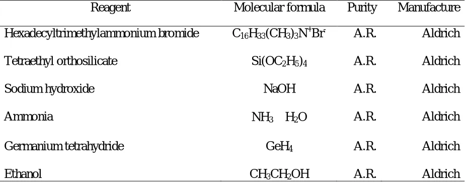
Table 2.1 Chemical reagents used in this study
Reagent Molecular formula Purity Manufacture
Hexadecyltrimethylammonium bromide C16H33(CH3)3N+Br- A.R. Aldrich
Tetraethyl orthosilicate Si(OC2H5)4 A.R. Aldrich
Sodium hydroxide NaOH A.R. Aldrich
Ammonia NH3‧H2O A.R. Aldrich
Germanium tetrahydride GeH4 A.R. Aldrich
Ethanol CH3CH2OH A.R. Aldrich
2.2. Synthesis Techniques
2.2.1. General Techniques to synthesis MCM-41
Typically, the silica source (e.g., tetraethylorthosilicate) is added to a clear alkaline
aqueous solution containing micelle-forming surfactant and PH adjustment catalyst (e.g., Sodium
hydroxide or ammonium hydroxide) under constant stirring. In this study, CTAB, which have a
hydrophilic headgroup and a hydrophobic tail group, were used as the mesostructure directing
agents. When the hydrolysis process is triggered, the silica source starts to form multidentate,
multicharged anions, which can cooperatively interact with the surfactants to assemble into a
12
1) At room temperature, 4 g of hexadecyltrimethylammonium bromide (CTAB) was
dissolved in 540 ml of distilled water under vigorous stirring
2) 410 ml of aqueous ammonium (25%) was added to the solution and the
temperature was raised to 341 K
3) 20 ml of TEOS was added dropwisely to the solution, forming white precipitates
4) The reaction was performed at 341 K under strong stirring for 2h
5) The white products were filtered, washed with distilled water and dried in an air
oven at 314 K for future use.
2.2.2. Encapsulation of Ge nanoparticles into MCM-41
Three different methods for incorporating Ge semiconductor nanoparticles into MCM-41
networks have been investigated. The detailed synthesis procedures are listed as below:
Method 1: H2 reduction
1) The host mesoporous silicate were calcined at 823 K for 4 h to remove the
surfactant molecules and other organic species in the channels of MCM-41
2) 2 ml of GeBr4 was added in 5 ml of THF solution under strong stirring
3) MCM-41 powders were placed in a three-neck flask and vacuum dried for 15 min
4) At room temperature, the GeBr4 solution was impregnated into to flask very
quickly until the powders were completely immersed in the solution, and then argon flow was
introduced into the system
5) Repeat the vacuum drying and impregnation step 2-3 times until the color of
MCM-41 powders turned from white to red-orange
6) The powders were placed in a quartz container and transferred to a tube furnace.
Under constant hydrogen flow, the furnace was heated up to 823 K for 10 h, and then 873 k for
30 min
7) After the sample was cooled down to room temperature, its color turned to
13
Method 2: Chemical vapor infiltration and pyrolysis
1) The host mesoporous silicate were calcined at 823 K to remove the surfactant
molecules and other organic species in the mesopores channels
2) As-prepared MCM-41 hosts were placed in a quartz container in a tube furnace
3) The samples were thermally dehydrated under vacuum at 423 K for 4 h
4) Germaniumtetrahydrid gas was constantly introduced through the chamber at
room temperature for 1 h
5) The reaction chamber was heated up to 823 K leading to pyrolysis of the GeH4 to
form Ge nanoparticles
6) The sample was vacuum dried at room temperature to remove residual GeH4 and
H2 gases
7) The sample was washed by deionized water and ethanol, followed by annealing in
static vacuum at 973 K for 1-2h.
Method 3: Na-Naphthalene reduction
1) The host mesoporous silicate were calcined at 823 K to remove the surfactant
molecules and other organic species in the mesopores channels
2) MCM-41 powders were transferred to a three-neck flask and vacuumed for 15
min to remove the air inside the pore system
3) 1 ml of the precursor GeBr4 were dissolved in THF, and then impregnated into the
flask under vacuum
4) To initiate the growth of Ge nanoparticles, 2 ml of 1 M solution of
Sodium-Naphthalene in tetrahydrofuran was injected into the flask. The reaction was remained at room
temperature for 1 h. In the course of the reduction the color of the solid changed from white to
yellow-orange
5) Ge-filled MCM-41 composite was collected as a powder by filtering it from the
14
6) The sample has a grey color and was wash with dry tetrahydrofuran and deionized
water to remove the Ge at the outer surface of MCM-41
7) The washed MCM-41 loaded with Ge nanoparticles was vacuum dried and
characterized by various analytical techniques.
2.3. Analysis and Characterization
2.3.1. X-ray Powder diffraction (XRD)
X-ray powder can be used to investigate the structure and crystallinity of the MCM-41
particles. The XRD patterns of all samples were measured with a Phillips-X’PERT X-ray powder
diffraction system (Cu, Kα= 1.5406 Å). The data collection and analysis were carried out using
the software supplied with the diffractometer. The size of the particles can be estimated by the
Scherrer equation: Dc=Kλ/βcosθ.
2.3.2. Transmission Electron Microscopy (TEM)
All transmission electron microscopy was performed using a JEOL 2010 electron
microscope operated at 200 kV. Samples for the TEM measurement were suspended in ethanol
and one drop of the dispersion was placed on a graphite foil on a copper grid and allowed to dry,
leaving the crystallites in random orientation on the foil.
2.3.3. Energy Dispersive Spectroscopy (EDS)
Elemental analysis was carried out using an EDAX attachment on a JEOL 2010 TEM
with the electron beam focused to two nanometers. EDS is a technique used to identify the
elemental composition of a sample or small area of interest on the sample. During the
examination process, a solid-state detector is used to collect the characteristic X-rays emitted
from a sample. By analyzing the emitted X-rays, the elemental composition of the sample can be
determined. A collection of X-ray energies from 0 to 40 KeV can be collected and displayed on a
15
present in the sample. The area included within a peak is roughly proportional to the amount of
the corresponding element in the sample, although the detector efficiency decreases with
increasing energy. The EDS system can be used for quantitative analysis by counting the X-rays
received in the channels that correspond with a peak of interest. EDS is a powerful tool for
microanalysis of elemental constituents.
2.3.4. Scanning Electron Microscope (SEM)
SEM was used to characterize the structures and morphologies of the processed particles.
SEM experiments were performed on dry powders with a LEO 1530 SEM with a field emission
gun without sample sputtering.
2.3.5. N2 absorption and desorption
Adsorption and desorption isotherms for nitrogen were obtained at 77K using a
Micromeritics ASAP-2010. The samples were outgassed at 573K for 12h before measurements
were performed. Specific surface area values were obtained using the BET
(Brunauer-Emmett-Teller) equation. The pore size distribution data was obtained using the BJH
16
CHAPTER 3 PREPARATION OF THE MESOPOROUS SILICA WITH
VARIOUS MORPHOLOGIES
In the past decade, a great amount of work has been dedicated to the synthesis of
mesoporous silica material. Different mesostructures have been synthesized through many
different strategies, such as MCM-41 [7], SBA-15 [10], MSU-1 [11] and etc. The synthesis
process has been well developed as well as the mechanism explanation, which can provide
fundamental guidance to the fabrication work. Some important discoveries with respect to the
morphology control of MCM-41 are listed below:
(1) Ozin and co-workers [45] first demonstrated the co-presence of various
morphologies of mesoporous silicates particles under acidic conditions. The materials were
synthesized in an extremely dilute solution of TEOS and surfactant with very low pH conditions.
(2) Huo et al. [46] demonstrated that mesoporous silica could be produced in the form
of marblelike spheres of about 1 mm in diameter. The size of the spheres was reported to be
controlled by the stirring speed.
(3) Grün et al. [47] reported the synthesis of spherical silica particles featuring the
MCM-41 structure, whose size ranged from 400 to 1100 nm. Their synthesis procedure was a
modification to Stöber’s synthesis [48] of monodisperse silica spheres by adding cationic
surfactant to the reaction mixture during the formation of MCM-41.
(4) Büchel et al. [49] reported a novel method for the synthesis of
submicrometer-sized (~ 700 nm) solid core/mesoporous shell silica spheres. Their method was based on a
combination of the Stöber approach [48], the Unger growth process [50], and the Kaiser
approach [51].
(5) Various morphologies of mesoporous silica were reported such as Teraski et al.
[52] reported the method for the synthesis of single crystal SBA-16; Cai Q. et al. [53] reported
the fabrication of single crystal MCM-41; Lin. H. P. [54] reported the synthesis of thin-film
17
Although various morphologies have been previously achieved, little is known about the
formation of helical, slice and rice-like morphologies of mesoporous silica. Here in, we report
the control of morphologies of silica particles, where MCM-41 silica monolith, mesoporous
silica slice, rice-like mesoporous silica and helical mesoporous silica are produced through
pathways of extremely low surfactant concentrations with a basic medium. The corresponding
formation mechanisms were proposed to interpret the morphogenetic control on the basis of
deposition of self-assembled silicate rod-like micelles.
3.1 Synthesis of micrometer-sized MCM-41 particles
3.1.1. Synthesis conditions
Typical synthesis of ordered MCM-41 silica particles using surfactant templating were
studied here according to the procedure reported in the literature [53]. The ratio of the starting
materials is 4 g (CTAB): 540 ml (H2O): 410 ml (NH3‧H2O): 20 ml (TEOS). Aqueous ammonia
was used as the catalyst and CTAB was used as templating surfactant. Five routes (Table 3.1.)
were opted to synthesize the mesoporous MCM-41 with different particle sizes or morphologies.
Table 3.1 Synthesis conditions of MCM-41.
No. Stirring speed Reaction Temp. (K) Time Seed Crystal Product
1 Strong 313 2h None Sphere
2 Strong 341 4h Powder Rod
3 Static R.T. 3 ~ 4d Powder Film
4 Strong 304 12h Solution Rice-like
5 Strong 341 2h EtOH Helical
3.1.2. Results and discussions
MCM-41 powders synthesized through route 1 were filtered and washed with distilled
water, then followed by calcinations in air at 873 K for 4 h. To investigate the morphology of the
sample, scanning electron microscopy (SEM) and transmission electron microscopy (TEM)
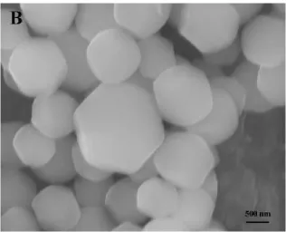
studies were performed on the samples. From the SEM images (Figure 3.1A and B), we observed
monodisperse spherical MCM-41 particles with diameters ranging from 0.3 ~ 1 μm and with a
18
average distance of the particle interstices is c.a. 100 nm. Figure 3.1B shows that a single crystal
of MCM-41 in the shape of hexagon can grow to be as large as 2×2 μm and these hexagonal
MCM-41 particles are highly regular in shape.
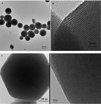
The microstructures of the as-synthesized MCM-41 are clearly revealed by TEM and
HRTEM. Figure 3.2A shows the typical TEM images of the spherical MCM-41 samples, which
exhibit a hexagonal external surface morphology. The size of the particles ranges from 400 to
1000 nm, which is close to that obtained from SEM results. TEM images (Figure 3.2B, C, D) of
the samples show the existence of highly ordered hexagonal array and streak structural features.
The streak is the view of the crystals whose c axis is perpendicular to the line of vision (Figure
3.2B). Figure 3.2C shows the image of a perfect hexagonal single crystal of MCM-41 without
intergrowth and twinned aggregation. Enlargement of the crystals (Figure 3.2D) is the view of
the crystals whose c axis parallels the line of vision, which clearly reveal the long-range highly
ordered mesoporous structures of MCM-41.
We suggest that the formation of the MCM-41 spheres is through the pathway 2 of
Liquid Crystal Templating mechanism [7], i.e. the nucleation involving silica-surfactant
interactions facilitate the assembly of inorganic-organic micelles. During the reaction, we
observed that the clear solution turned cloudy immediately after the mixing of surfactant and
inorganic solution containing silica precursors. This indicates the formation of inorganic-organic
self-assembled silicate micelles (SSMs) through ion exchange of silicate oligomers with Br- and
OH- anions. Without the presence of silicate oligomer, SSM might not form under the diluting
condition [55]. Then during the condensation of the silicate groups on the SSMs, the
arrangement and deposition of the micelles are governed by the inside electrostatic interactions
19
20
Figure 3.2 TEM images of ordered MCM-41 particles: A) Scale bar, 500 nm. B) Scale bar, 20 nm. C) Scale bar, 100 nm. D) Scale bar, 20 nm).
From the in situ particle size development study, it was suggested that monodispersity of
the particles is because the particles were generated successively, growing rapidly to the same
maximum size one after another under diluting conditions [56]. This is consistent with our
21
The internal structure of the porous monodisperse silica spheres is dependent on the type
of the surfactant. And the length of the surfactant-silicate micelles is determined by the solvent.
In this experiment, the solvent containing CTAB and ammonia favors the formation of
monodisperse mesoporous silica spheres possessing highly ordered hexagonal regularity. These
spherical MCM-41 particles are of great interest for applications in chromatography [57-60] and
cosmetics [61].
3.2 Synthesis of large monolith MCM-41 rod
3.2.1. Synthesis conditions
In route 2, we used MCM-41 spherical particles obtained via route 1 as the seed crystal to
grow large monolith MCM-41 silica. After the solutions of CTAB and aqueous ammonium were
completely mixed under vigorous stirring, the seed crystal was added to the solution. Then the
system was heated up to 341 K and the TEOS was added drop by drop. The rest procedures were
the same with route 1.
3.2.2. Results and discussions
The seed crystal growth procedures were repeated three times for comparing the effects
to particles size and morphology. For the first time of seed crystal growth, we observed that the
as-produced particles have a rod shape and the size increases markedly. Figure 3.3 shows the
typical SEM images of the monolith MCM-41 rods. It is clearly seen that the length of the rods is
22
Figure 3.3 SEM images of rod-like MCM-41 from the 1st time of seed crystal growth.
The SEM images of MCM-41 particles from the second time of seed crystal growth are
shown in Figure 3.4. The particles obviously increase in size than those obtained from the first
time seed crystal growth and the size can be as large as 3×1.5 μm (length×diameter). We also
observed that some of the particles from the first time seed crystal growth (Figure 3.3) have a
more marked curvature than those showed in Figure 3.4B, which have a perfect rod shape. This
may be caused by the charge density change of the anionic silicate oligomers during the
condensation process. It is well-known that the ratio of the interaction of the silicate oligomers
among the Gouy-Chapman region to that of the hydrocarbon chains resulting from the van der
Waals forces is related to the curvature of the formed micelles [62]. The lamellar phase formed
initially by highly charged anionic silicate species and the positively charged surfactant
hydrophilic groups is electronically neutral. The initiation of the silica condensation process
reduces the negative charge density of the silicate oligomers, and then the hybrid
inorganic-surfactant interface begins to develop a more marked curvature. This effect can be extended to
the macrometric surface of the particles, which have less mechanical strength and thus bend
easily. When the particles obtained from the first time seed crystal growth were used as seed
23
24
25
Consider the reaction equilibriums in the nucleation process (Equation 3.1, 3.2 and 3.3).
In conditions where the concentration is low and the pH is high, the equilibrium may shift
backward to dissolve MCM-41 particles. We found that at this temperature, the particles would
dissolve in the solution very slowly and remove the irregular array on the surface. This process
can polish the surface of the particles, which can be used as seed crystal for the next step of
nucleation and growth.
~ + ↔ ~ + (3.1)
~ + ~ ↔ ~ − − ~ + (3.2)
~ + ~ ↔ ~ − − ~ + (3.3)
However we didn’t observe obvious change for the third time of seed crystal growth
(Figure 3.5). The shape and size of MCM-41 rod are similar with those shown in Figure 3.4. This
indicates that there is a size limit for the growth of the crystal. When the limit has been reached,
the particles would prefer to form new crystal nucleus instead of growing on the existed particles.
This has been proved by the concomitant small particles (Figure 3.4B) with an average size of
500 nm.
3.3 Synthesis of MCM-41 film
3.3.1. Synthesis conditions:
According to synthesis route 3 (Table 3.1), 410 ml of ammonia (25%) solution was
mixed with 540 ml of distilled water. Then 4.0 g of surfactant (CTAB) was added to the solution
with vigorous stirring. The mixture was heated up to 341 K and 10.0 g of the spherical MCM-41
particles obtained in section 3.1 was added to the solution. The synthesis system was maintained
at 341 K until MCM-41 particles were completely dissolved, and then cooled down to room
temperature. The system was maintained in static conditions for 3 ~ 4 days. The white
precipitates appeared on the surface the solution were filtered, washed with distilled water and
dried in air oven for future characterization.
26
3.3.2. Results and discussions
Through this static growth method, MCM-41 films with thickness from tens of
nanometers up to about 300 nm have been synthesized at the air-liquid interface. The sample was
collected directly from the synthesis solution and characterized by SEM. Figure 3.6A clearly
shows the SEM images of the continuous and transparent MCM-41 films with a thickness of
only about 0.1 nm. It has a smooth surface and very strong mechanical strength. The sample was
filtered by a Buchner funnel and still remains the integrality of the film morphology (Figure
3.6B).
Figure 3.6 SEM images of MCM-41 thin film. A) the sample was collected directly from the synthesis solution. B) the sample was collected after filtration.
Figure 3.7 shows the SEM images of MCM-41 films with thicknesses of about 300 nm.
Most of MCM-41 films are stacking together (Figure 3.7A). Figure 3.7B shows that the films
have smooth surfaces. The film surface growing into the solution shows roughness on the
mesoscopic scale (Figure 3.7C), which might represent a silica replica of the disposition of
27
Figure 3.7 SEM images of MCM-41 films with thickness of about 300 nm: A) Scale bar, 4 μm. B) Scale bar, 4 μm. C) Films immersed in the solution. D) Films dispersed in ethanol.
When the sample was dispersed in ethanol, a wrinkle structure can be seen on the surface
(Figure 3.7D). This implies that ethanol will destroy the smoothness of the surface of MCM-41
films.
It was proposed that the surfactant was used as template at the interface between air and
water for the deposition of silicates to form mesoporous MCM-41 silica [63]. The dissolved
MCM-41 particles are in equilibrium with the synthesis solution, which may form
surfactant-silicate micellar aggregates in the solution, which may further form MCM-41 mesostructures
through condensation and polymerization processes. The surfactant micelles at the interface of
the solution and air react differently with those immersed in the solution. With extremely low
28
equilibrium with the synthesis solution, thus the arrangement of the micelles at the air-liquid
interface may be in the form that the micelle rods are parallel to the interface.
Figure 3.8 Graphical illustration of the proposed mechanism for the formation of mesoporous silica film at the air-water interface [63].
After a long time (3 ~ 4 days) of self-assembly of the surfactant-silicate mecelles under
static conditions, the upper surface of the film was dissolved by the synthesis solution and
appeared as a smooth surface. By contrast, the surfactant-silicate might randomly deposit on the
lower surface of the film and thus showed a rough structure.
3.4 Synthesis of uniform rice-like MCM-41 particles
3.4.1. Synthesis conditions:
After MCM-41 particles synthesized in section 3.1 were filtered, the rest synthesis
solution was also collected as the reaction solution here. 410 ml of ammonia (25%) solution, 4.0
g of surfactant (CTAB) and 540 ml of collected solution were mixed under vigorous stirring at
341 K. The system was cooled down to 308 K. 10 ml of TEOS solution was added to the system
very slowly by a syringe pump (12 h). The temperature was 300 K after the reaction was
29
30
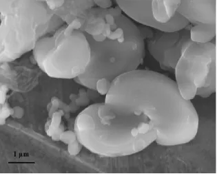
3.4.2. Results and discussions
The SEM images of as-synthesized MCM-41 particles are show in Figure 3.9. The length
of the rice-like particles ranges from 300 ~ 600 nm and the average diameter is about 300 nm.
We suggest that the suspended silicate species in the reaction solution provide nucleation sites
for the formation of new MCM-41 crystal. After the silica precursor was introduced into the
solution, the crystallization process happened very quickly due to the existence of many
nucleation sites. Because the nucleation sites are homogeneously distributed in the solution, the
interaction between the surfactant micelles and the silicate species completed in a very short time
in this supersaturated solution, which prefers the formation of many small sized rice-like
MCM-41 particles.
3.5 Synthesis of helical MCM-41 silica
3.5.1. Synthesis conditions:
In this synthesis route, before adding the TEOS solution, 10 ml of EtOH solution was
added to the synthesis system. The reaction was performed at 341 K under strong stirring for 2 h.
The products were collected after filtration.
3.5.2. Results and discussions
Many helical MCM-41 silicas were observed by SEM (Figure 3.10). A possible
explanation for the formation of helical MCM-41 can rely on the slow gelation process. The
existence of the EtOH solution slows down the hydrolysis and condensation processes of silicate,
causing the co-existence of liquid sol phases and solid gel phases. During the filtration process,
the interaction between the sol and gel caused by the filtration pressure helps to form the helical
MCM-41.
3.6 Summary
The key point in the sol-gel synthesis of mesostructured silica is to thoroughly adjust the
chemical, spatial and structural properties of the templating surfactant. Prior to obtain
31
32
It has been found that the distributions of these anionic silicate species are sensitive to pH,
temperature, cation, and Si concentration. A reduction in silicon concentration or increase in
temperature or pH favors the formation of monomer and small oligomers [64]. One of the
reasons of choosing dilute solution is because increasing silicate concentration results in the
large extent of oligomerization.
As described previously, the phase organization of surfactant and inorganic
polymerization are the two main processes during the formation of mesoporous silica. Fast
inorganic condensation will be a serious problem for morphology control. From the kinetic point
of view, in conditions where condensation is slow, the kinetic constants of the different processes
should be ordered as follows:
> > (3.4)
We used the extremely dilute solution routes to investigate the effects of temperature,
stirring speed and seed crystal, which are directly affecting the interactions to generate a
well-defined hybrid interface. Under the dilute solution condition, these experiment parameters can
provide an effective way to control gelation and precipitation processes, and subsequently
33
CHAPTER 4 ENCAPSULATION OF GEMANIUM NANOPARTICLES
INSIDE MCM-41 MESOPORES
Recent success in growing and loading semiconductors like Si [65], TiO2 [66], GaAs [67],
CdS [68, 69] into the MCM-41 mesopores has opened a new research field in the electronic and
optical applications of mesoporous silica. Due to the quantum confinement effects and guest-host
effects, the semiconductor/mesoporous composites exhibit unique optical properties, such as
blue-shift, fluorescence, photoluminescence. Compare with Si, Ge is an important VI
semiconductor with a narrow bandgap and similar electron affinity [70].
In this study, we chose GeBr4 or GeH4 as the metal ion sources, in contrast to the
traditional starting materials such as the expensive and toxic GeCl2·dioxane used in previously
reported synthesis route [71, 72]. We also developed three different synthesis methods to
compare the pore filling efficiency of Ge semiconductors in the silica networks.
4.1. H2 reduction method
4.1.1. Experiment method
In this synthesis, GeBr4 was used as Ge precursor and the formation of Ge nanoparticles
was completed by H2 reduction. Three samples were obtained under different experiment
condition. Sample 1 was the result of single impregnation of the precursor and sample 2 was
obtained after multiple impregnations. Sample 3 was the products of multiple impregnations and
was annealed at 823 K.
The first step of our synthesis process concerns the homogeneous adsorption of
Germanium cationic species on the silica walls that form the pore surface, which is completed by
impregnation of the THF solutions with soluble Germanium cationic species. Figure 4.1
schematically shows the chemical process of this step. Because the silica walls are partially
soluble when the pH is above 10 [73], THF solutions were used here instead of aqueous
34
Figure 4.1 schematic reaction sequences for the synthesis of Ge nanoparticles in MCM-41.
The impregnated MCM-41 powders were washed by THF solutions, EtOH and distilled
water to eliminate reactive in excess, and above all to avoid the accumulation of cationic species
at the outer surface of MCM-41 powders.
The last step of the process is the homogeneous formation of nanoparticles via the
precipitation of the ionic species. This requires the use of gaseous hydrogen, which rapidly
diffuses into the film leading to simultaneous precipitation within all the pores.
4.1.2. Electron Microscope results
The TEM image of Ge@MCM-41 composite from single impregnation is shown in
Figure 4.2. It reveals that the hexagonally ordered mesostructure (Figure 4.2B, higher
magnification) of the host material MCM-41 was unaffected by the presence of Ge inside the
pores. This indicates that the H2 reduction technique does not cause significant deterioration of
MCM-41 framework. The Ge@MCM-41 composite exhibits two basic types of diffraction
pattern. The electron diffraction patterns shown in Figure 4.2C are obtained by viewing the
Ge@MCM-41 composite along the axis of the hexagonal pores. This gives a [0001] pattern with
six-fold symmetry. When viewed normal to the hexagonal pore axis, a one-dimensional
diffraction pattern was obtained (Figure 4.2D) These electron diffraction patterns are in good
agreement with the reported results [74] and confirm that the ordered network of MCM-41
35
36
Figure 4.3 TEM images of Ge@MCM-41 sample 2: A) Scale bar, 200 nm. B) Scale bar, 100 nm.
Figure 4.4 TEM images of Ge@MCM-41 sample 3: A) Scale bar, 500 nm. B) Scale bar, 100 nm.
The Ge nanoparticles inside the channels of MCM-41 are also confirmed by high
magnification TEM images shown in Figure 4.2B, Figure 4.3B and Figure 4.4B. The Ge
nanocrystallites appear as dark substances among the channels of MCM-41. The diameter of
37
The TEM analysis (Figure 4.4) and SEM results (Figure 4.5) of sample 3 showed the
thermal stability of MCM-41 mesostructures after annealing at 823 K. In addition,
Ge@MCM-41 composite exhibits stronger electron contrast than the empty MCM-Ge@MCM-41 and moreover the
semiconductor-filled composite was much more stable under the electron beam than the empty
MCM-41 (Figure 3.2D). These observations indicate that the inner walls of the silica host
material have been coated with Ge particles.
Figure 4.5 SEM images of sample 3: A) Scale bar, 2 um. B) Scale bar, 500 nm.
38
4.1.3. XRD results
The calcined MCM-41 was vacuum dried and characterized by low-angle XRD
measurements, which exhibit the characteristic reflections of high-quality hexagonal
mesostructures (Figure 4.6).
Figure 4.6A shows the comparison of XRD patterns of empty MCM-41 and
Ge@MCM-41 composites for the low-angle region (2θ=1-10o). It is observed that the highly ordered
hexagonal pore structure of MCM-41 is still intact, while the intensities of the characteristic
XRD reflections of MCM-41 are reduced for Ge@MCM-41. This can be attributed to pore
filling of the host material, which reduces the scattering contrast between the pores and the walls
of the molecular sieve [75] (particles are confined to the pores of MCM-41).
In addition, the peaks of Ge@MCM-41 sample are obviously shifted to higher angle. The
pore size estimated from the equation (d100 – 1) nm is reduced from 2.6 nm to 2.0 nm. This also
provides evidence for the pore filling of Ge nanoparticles.
Figure 4.6B shows the wide-angle XRD pattern of Ge@MCM-41. A very broad
reflection peak at 26o corresponds to the diffraction of the amorphous wall of MCM-41. There is
no direct evidence in the XRD pattern showing the crystallinity of Ge nanoparticles inside
MCM-41. We suggest the XRD peaks of Ge crystal may be too weak and too broad to be
observed due to the small size of the nanoparticle (< 2.6 nm).
4.1.4. EDS analysis
To confirm the formation of Ge nanoparticles, three samples were characterized by EDS
(Figure 4.7). The EDS analysis was performed on the mesoporous region (where no Ge particles
are externally visible). Figure 4.7B shows stronger Ge signals than Figure 4.7A indicating the
confinement of Ge nanoparticles inside the pores of MCM-41 was enhanced by multiple
precursor impregnations. In the EDS analysis, in addition to Ge peaks, Si and O peaks (MCM-41)
as well as Cu and C peaks (support grid) and Br (surfactants) were detected. From the EDS
39
Element Weight% Atomic%
O K 31.35 47.81 Si K 54.65 47.48 Ge K 14.00 4.71
Totals 100.00
Element Weight% Atomic%
O K 23.57 41.86 Si K 45.54 46.06 Ge K 30.89 12.09
Totals 100.00
Element Weight% Atomic%
O K 37.06 54.03 Si K 50.56 41.99 Ge K 12.38 3.98
Totals 100.00
Figure 4.7 EDS patterns of three samples through H2 reduction synthesis route: A) Sample 1 via single
impregnation. B) Sample 2 via multiple impregnations. C) Sample 3 via multiple impregnations and after calcinations.
4.1.5. N2 adsorption-desorption study
Figure 4.8 shows the nitrogen adsorption-desorption isotherms of empty MCM-41
powder and Ge@MCM-41 powder. The results were obtained at 77 K. All of the isotherms are
40
Figure 4.8 Nitrogen adsorption-desorption isotherms of (a) Empty MCM-41 and (b) Ge@MCM-41.
The BET surface area of the empty MCM-41 was 922 m2/g and the pore-size distribution
of about 2.7 nm (full-width at half-maximum, FWHM = 0.2 nm) was calculated from BJH
(Barrett-Joyner-Halender) theory [77] on the basis of desorption data from the N2 studies. The
pore size was estimated as the value corresponding to the maximum of the BJH pore-size
distribution.
The N2 sorption studies on Ge@MCM-41 proved evidence of pore filling of the host
matrix. A well-defined step occurs approximately at ⁄ = 0.1 ~ 0.3, which is associated with
the filling of the mesopores due to capillary condensation. After formation of nanoparticles, the
amount of adsorbed nitrogen decreases and the inflection point of the step shifts to a smaller
⁄ . This is directly showed as decrease in pore volume of Ge@MCM-41 with respect to
empty MCM-41. The decrease in BET surface area of Ge@MCM-41 (713 m2/g) in comparison
with that of empty MCM-41 (922 m2/g), also implies Ge semiconductor clusters have been
confined inside the channels of MCM-41.
Loading Ge nanoparticles into MCM-41 through H2 reduction is actually a process of in
situ formation of the Ge nanoparticles inside mesoporous MCM-41. The hydroxyl group on the
internal surface of MCM-41 will easily absorb the GeBr4 molecules to form Si-O- GeBr3 species
(Figure 4.1). The gaseous hydrogen diffuses quickly in the pore systems and reduces the Ge4+
41
41 + → 41− + (4.1)
41− + → @ 41 + 3 (4.2)
4.2. Vapor phase epitaxy
4.2.1. Experiment method
In this synthesis route, Germane (GeH4) was used as Ge precursor. The host MCM-41
was vacuum dried for 4 h to remove the surfactant and organic species inside the pore system.
Then the vapor phase GeH4 was introduced into the mesopores of MCM-41 under constant flow
for continuous 1 h. After the gaseous GeH4 was homogeneously dispersed in the pore system, the
reaction chamber was heated up to 823 k leading to the pyrolysis of the precursors.
4.2.2. Results and analysis
Figure 4.10 shows the representative TEM images for the Ge@MCM-41 synthesized
through this method. The high magnification TEM image (Figure 4.10B) revealed that the
mesoporous structures are intact after loading Ge nanoparticles inside the pores. However, the
dark edge and some dark spots with diameters ranging from 5 to 15 nm show that a great amount
of Ge grew on the outside surface of the host MCM-41. From the ratio of dark spots and white
spots in the HRTEM image it can be estimated that only half of the pores were successfully
loaded with Ge nanoparticles, which may be attributed to the low yield of gaseous precursor.
Although the gas flow in the reaction chamber was continuous, it may not flow into the pore
system consecutively. On the other hand, the host MCM-41 was immersed in the gas phase and
once the pyrolysis process was triggered, most of the pryolysis products (Ge) would precipitate
on the outside surface of the host MCM-41 and prevent more gaseous precursor getting inside
42
Figure 4.9 TEM images of Ge@MCM-41 synthesize through Vapor phase epitaxy method.
4.3. Redox reaction using Na-Naphthalene
4.3.1. Experiment method
The Ge nanoparticles were introduced within the mesoporous powders by impregnation
with a THF solution of GeBr4 and followed by a reduction reaction through Na-Naphthalene
solution.
A chemical attachment of a molecular precursor for germanium was obtained by reacting
neat GeBr4 with the silanol groups at the surface of the mesoporous ordered MCM-41 at room
temperature. The excess of GeBr4 was removed in vacuo and the functionalized MCM-41 was
vacuum dried for several hours in order to remove residual hydrogenbromide. Subsequently, an
excess of a 1M solution of Na-Naphthalene in THF was added to produce an orange-colored,
X-ray amorphous hydrogenated germanium in the pores of the substrate. Annealing of this material
at 773 K for 2 h (under argon atmosphere) yielded grey crystalline germanium in the mesopores
43
4.3.2. Results and analysis
To confirm the formation of Ge nanoparticles, the sample was characterized by EDS
(Figure 4.11). A very strong signal of Ge was shown in the EDS pattern, which suggests the
successful loading the Ge semiconductor clusters in the mesoporous structures.
Figure 4.10 EDS pattern of Ge@MCM-41 composites synthesized through Na-Naphthalene reduction.
44
The TEM results of Ge@MCM-41 show that most of the silica networks have been
destroyed and many Ge nanoparticles with size bigger than the host MCM-41 pore size (2.6 nm)
have been observed (Figure 4.12).
4.4. Summary
Three different synthesis methods have been used to grow monodisperse Ge
nanoparticles in the mesoporous silica networks.
The H2 reduction synthesis route to incorporate Ge nanoparticles into 3D hexagonal
mesoporous silica is very simple and effective and can be generalized to other II-VI
semiconductors. X-ray diffraction and electron microscopy characterizations unambiguously
demonstrate that the mesoporous structure allows to control the particle size and the organization
of Ge nanoparticles. This leads to the growth of a 3D lattice of semiconductors at a large scale.
The impregnation of precursor solutions can be well controlled because the hydroxyl functional
groups bind with GeBr4 easily and this step can be repeated many times until the full filling of
the pores of MCM-41. The gaseous H2 can penetrate the pore system quickly to reduce Ge4+ to
Ge.
The vapor phase epitaxy method can also successfully load Ge into the pore system. For
full filling Ge nanoparticles of the pores of MCM-41, multiple cycles of outside surface
washing-vapor phase epitaxy seems to be feasible. However the expensive precursors limit the
broad use of this method.
The breakage of the mesostructures of MCM-41 caused by Na-Naphthalene solution
suggests the importance of choosing proper solvent. The interaction between the pore walls and
![Figure 1.1 The phase diagram of cationic surfactant CTAB in aqueous solution [14].](https://thumb-us.123doks.com/thumbv2/123dok_us/8935736.1847824/11.612.166.446.402.702/figure-phase-diagram-cationic-surfactant-ctab-aqueous-solution.webp)
![Figure 1.2 Schematic model of liquid crystal templating mechanism via two possible pathways [7]](https://thumb-us.123doks.com/thumbv2/123dok_us/8935736.1847824/13.612.99.523.80.258/figure-schematic-liquid-crystal-templating-mechanism-possible-pathways.webp)
![Figure 1.3 Schematic model for transformation mechanism from lamellar to hexagonal phase [18]](https://thumb-us.123doks.com/thumbv2/123dok_us/8935736.1847824/14.612.144.472.208.347/figure-schematic-model-transformation-mechanism-lamellar-hexagonal-phase.webp)
![Figure 1.4 Schematic representation of the different types of silica-surfactant interfaces [2]](https://thumb-us.123doks.com/thumbv2/123dok_us/8935736.1847824/15.612.86.531.85.361/figure-schematic-representation-different-types-silica-surfactant-interfaces.webp)
![Figure 1.5 The interrelationship between solvent, template and inorganic species [20]](https://thumb-us.123doks.com/thumbv2/123dok_us/8935736.1847824/16.612.219.394.314.483/figure-interrelationship-solvent-template-inorganic-species.webp)