ISSN(Online): 2319-8753
ISSN (Print): 2347-6710
I
nternational
J
ournal of
I
nnovative
R
esearch in
S
cience,
E
ngineering and
T
echnology
(A High Impact Factor, Monthly Peer Reviewed Journal)
Vol. 5, Issue 2, February 2016
Improved Active Power Filter Performance
for Renewable Power Generation Systems
Dr.V.Balakrishna Reddy
Professor, Dept of EEE, Vijaya Rural Engg College, Nizamabad, Telangana State, India
ABSTRACT: An active power filter implemented with a four-leg voltage-source inverter using a predictive control scheme is presented. The use of a four-leg voltage-source inverter allows the compensation of current harmonic components, as well as unbalanced current generated by single-phase nonlinear loads. A detailed yet simple mathematical model of the active power filter, including the effect of the equivalent power system impedance, is derived and used to design the predictive control algorithm. The compensation performance of the proposed active power filter and the associated control scheme under steady state and transient operating conditions is demonstrated through simulations and experimental results.
KEY WORDS: PWM, harmonic distortion of the load (THD(L)), synchronous reference frame (SRF),PI,LPf.
I. INTRODUCTION
RENEWABLE generation affects power quality due to its nonlinearity, since solar generation plants and wind power generators must be connected to the grid through high-power static PWM converters . The non uniform nature of power generation directly affects voltage regulation and creates voltage distortion in power systems. This new scenario in power distribution systems will require more sophisticated compensation techniques.
Although active power filters implemented with three-phase four-leg voltage-source inverters (4L-VSI) have already been presented in the technical literature , the primary contribution of this paper is a predictive control algorithm designed and implemented specifically for this application. Traditionally, active power filters have been controlled using pretuned controllers, such as PI-type or adaptive, for the current as well as for the dc-voltage loops . PI controllers must be designed based on the equivalent linear model, while predictive controllers use the nonlinear model, which is closer to real operating conditions. An accurate model obtained using predictive controllers improves the performance of the active power filter, especially during transient operating conditions, because it can
quickly follow the current-reference signal while maintaining a constant dc-voltage.
ISSN(Online): 2319-8753
ISSN (Print): 2347-6710
I
nternational
J
ournal of
I
nnovative
R
esearch in
S
cience,
E
ngineering and
T
echnology
(A High Impact Factor, Monthly Peer Reviewed Journal)
Vol. 5, Issue 2, February 2016
II. FOUR-LEG CONVERTER MODEL
Fig. 1 shows the configuration of a typical power distribution system with renewable power generation. It consists of various types of power generation units and different types of loads. Renewable sources, such as wind and sunlight, are typically used to generate electricity for residential users and small industries. Both types of power generation use ac/ac and dc/ac static PWM converters for voltage conversion and battery banks for long term energy storage. These converters perform maximum power point tracking to
Fig. 1. Stand-alone hybrid power generation system with a shunt active power filter.
Fig. 2. Three-phase equivalent circuit of the proposed shunt active power filter
extract the maximum energy possible from wind and sun. The electrical energy consumption behavior is random and unpredictable, and therefore, it may be single- or three-phase, balanced or unbalanced, and linear or nonlinear. An active power filter is connected in parallel at the point of common coupling to compensate current harmonics, current unbalance, and reactive power. It is composed by an electrolytic capacitor, a four-leg PWM converter, and a first-order output ripple filter, as shown in Fig. 2. This circuit considers the power system equivalent impedance Zs, the converter output ripple filter impedance Zf, and the load impedance ZL.
The four-leg PWM converter topology is shown in Fig. 3. This converter topology is similar to the conventional three-phase converter with the fourth leg connected to the neutral bus of the system. The fourth leg increases switching states from 8 to 16 , improving control flexibility and output voltage quality , and is suitable for current unbalanced compensation. The voltage in any leg x of the converter, measured from the neutral point (n), can be expressed in terms of switching states, as follows:
(1)
The mathematical model of the filter derived from the equivalent circuit shown in Fig. 2 is (2)
where Req and Leq are the 4L-VSI output parameters expressed as Thevenin impedances at the converter output terminals Zeq .Therefore, the Thevenin equivalent impedance is determined by a series connection of the ripple filter impedance Zf and a parallel arrangement between the system equivalent impedance Zs and the load impedance ZL
(3)
ISSN(Online): 2319-8753
ISSN (Print): 2347-6710
I
nternational
J
ournal of
I
nnovative
R
esearch in
S
cience,
E
ngineering and
T
echnology
(A High Impact Factor, Monthly Peer Reviewed Journal)
Vol. 5, Issue 2, February 2016
III. DIGITAL PREDICTIVE CURRENT CONTROL
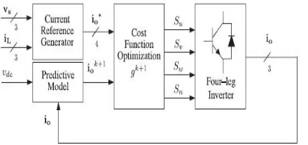
The block diagram of the proposed digital predictive current control scheme is shown in Fig. 4. This control scheme is basically an optimization algorithm and, therefore, it has to be implemented in a microprocessor. Consequently, the analysis has to be developed using discrete mathematics in order to consider additional restrictions such as time delays and approximations . The main characteristic of predictive control is the use of the system model to predict the future behavior of the variables to be controlled. The controller uses this information to select the optimum switching state that will be applied to the power converter, according to predefined optimization criteria. The predictive control algorithm is easy to implement and to understand, and it can be implemented with three main blocks, as shown in Fig. 4.
Fig. 4. Proposed predictive digital current control block diagram.
1) Current Reference Generator: This unit is designed to generate the required current reference that is used to compensate the undesirable load current components. In this case, the system voltages, the load currents, and the dc-voltage converter are measured, while the neutral output current and neutral load current are generated directly from these signals (IV).
2) Prediction Model: The converter model is used to predict the output converter current. Since the controller operates in discrete time, both the controller and the system model must be represented in a discrete time domain . The discrete time model consists of a recursive matrix equation that represents this prediction system. This means that for a given sampling time Ts , knowing the converter switching states and control variables at instant kTs , it is possible to predict the next states at any instant [k + 1]Ts .Due to the first-order nature of the state equations that describe the model in (1)–(2), a sufficiently accurate first-order approximation of the derivative is considered in this paper.
(4)
The 16 possible output current predicted values can be obtained from (2) and (4) as
As shown in (5), in order to predict the output current ioat the instant (k + 1), the input voltage value voand the converter output voltage vxN , are required. The algorithm calculates all 16 values associated with the possible combinations that the state variables can achieve.
3) Cost Function Optimization: In order to select the optimal switching state that must be applied to the power converter, the 16 predicted values obtained for io[k + 1] are compared with the reference using a cost function g, as follows:
+
(6)
ISSN(Online): 2319-8753
ISSN (Print): 2347-6710
I
nternational
J
ournal of
I
nnovative
R
esearch in
S
cience,
E
ngineering and
T
echnology
(A High Impact Factor, Monthly Peer Reviewed Journal)
Vol. 5, Issue 2, February 2016
then applied at the next sampling state. During each sampling state, the switching state that generates the minimum value of g is selected from the 16 possible function values. The algorithm selects the switching state that produces this minimal value and applies it to the converter during the k + 1 state.
IV. CURRENT REFERENCE GENERATION
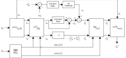
A dq-based current reference generator scheme is used to obtain the active power filter current reference signals. This scheme presents a fast and accurate signal tracking capability. This characteristic avoids voltage fluctuations that deteriorate the current reference signal affecting compensation performance . The current reference signals are obtained from the corresponding load currents as shown in Fig. 5. This module calculates the reference signal currents required by the converter to compensate reactive power, current harmonic, and current imbalance. The displacement power factor (sin φ(L) ) and the maximum total harmonic distortion of the load (THD(L) ) defines the relationships between the apparent power required by the active power filter, with respect to the load, as shown
(7)
where the value of THD(L) includes the maximum compensable harmonic current, defined as double the sampling frequency fs . The frequency of the maximum current harmonic component that can be compensated is equal to one half of the converter switching frequency.
The dq-based scheme operates in a rotating reference frame; therefore, the measured currents must be multiplied by the sin(wt) and cos(wt) signals. By using dq-transformation, the d current component is synchronized with the corresponding phase-to-neutral system voltage, and the q current component is phase-shifted by 90◦. The sin(wt) and cos(wt) synchronized reference signals are obtained from a synchronous reference frame (SRF) PLL . The SRF-PLL generates a pure sinusoidal waveform even when the system voltage is severely distorted. Tracking errors are eliminated, since SRF-PLLs are designed to avoid phase voltage unbalancing, harmonics (i.e.,less than 5% and 3% in fifth and seventh, respectively), and offset caused by the nonlinear load conditions and measurement errors . Equation (8) shows the relationship between the real currents iLx(t) (x = u, v,w) and the associated dq components (id and iq )
Fig. 5. dq-based current reference generator block diagram.
(8)
ISSN(Online): 2319-8753
ISSN (Print): 2347-6710
I
nternational
J
ournal of
I
nnovative
R
esearch in
S
cience,
E
ngineering and
T
echnology
(A High Impact Factor, Monthly Peer Reviewed Journal)
Vol. 5, Issue 2, February 2016
The current that flows through the neutral of the load is compensated by injecting the same instantaneous value obtained from the phase-currents, phase-shifted by 180◦, as shown next
(10)
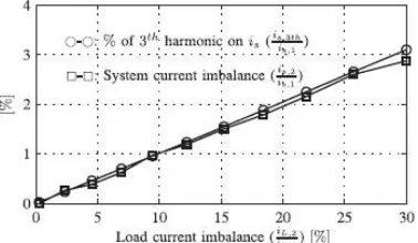
One of the major advantages of the dq-based current reference generator scheme is that it allows the implementation of a linear controller in the dc-voltage control loop. However, one important disadvantage of the dq -based current reference frame algorithm used to generate the current reference is that a second order harmonic component is generated in id and iq under unbalanced operating conditions. The amplitude of this harmonic depends on the percent of unbalanced load current (expressed as the relationship between the negative sequence current iL,2 and the positive sequence current iL,1 ). The second-order harmonic cannot be removed from id and iq , and therefore generates a third harmonic in the reference current when it is converted back to abc frame . Fig. 6 shows the percent of system current imbalance and the percent of third harmonic system current, in function of the percent of load current imbalance. Since the load current does not have a third harmonic, the one generated by the active power filter flows to the power system.
Fig. 6. Relationship between permissible unbalance load currents, the corresponding third-order harmonic content, and system current imbalance (with respect to positive sequence of the system current, is,1 ).
Fig. 7. DC-voltage control block diagram.
A. DC-Voltage Control
The dc-voltage converter is controlled with a traditional PI controller. This is an important issue in the evaluation, since the cost function (6) is designed using only current references, in order to avoid the use of weighting factors. Generally, these weighting factors are obtained experimentally, and they are not well defined when different operating conditions are required. Additionally, the slow dynamic response of the voltage across the electrolytic capacitor does not affect the current transient response. For this reason, the PI controller represents a simple and effective alternative for the dc-voltage control.
ISSN(Online): 2319-8753
ISSN (Print): 2347-6710
I
nternational
J
ournal of
I
nnovative
R
esearch in
S
cience,
E
ngineering and
T
echnology
(A High Impact Factor, Monthly Peer Reviewed Journal)
Vol. 5, Issue 2, February 2016
phase voltage. In the block diagram shown in Fig. 5, the dc-voltage vdc is measured and then compared with a constant reference value v dc. The error (e) is processed by a PI controller, with two gains, Kp and Ti . Both gains are calculated according to the dynamic response requirement. Fig. 7 shows that the output of the PI controller is fed to the dc-voltage transfer function Gs , which is represented by a first-order system (11)
G(s)= (11)
The equivalent closed-loop transfer function of the given system with a PI controller (12) is shown in (13)
C(s)= (12)
(13)
Since the time response of the dc-voltage control loop does not need to be fast, a damping factor ζ = 1and a natural angular speed ωn = 2π · 100 rad/s are used to obtain a critically damped response with minimal voltage oscillation. The corresponding integral time Ti = 1/a (13) and proportional gain Kp can be calculated as
(14)
(15)
V. SIMULATED RESULTS
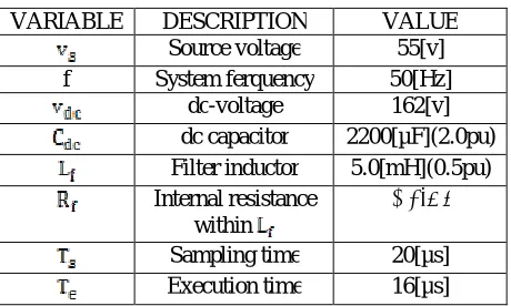
A simulation model for the three-phase four-leg PWM converter with the parameters shown in Table I has been developed using MATLAB-Simulink. The objective is to verify the current harmonic compensation effectiveness of the proposed control scheme under different operating conditions. A six-pulse rectifier was used as a nonlinear load. The proposed predictive control algorithm was programmed using an S-function block that allows simulation of a discrete model that can be easily implemented in a real-time interface (RTI) on the dSPACE DS1103 R&D control board. Simulations were performed considering a 20 [μs] of sample time. In the simulated results shown in Fig. 8, the active filter startsto compensate at t = t1 . At this time, the active power filter injects an
output current iouto compensate current harmonic components, current unbalanced, and neutral current simultaneously. During
compensation, the system currents is show sinusoidal waveform, with low total harmonic distortion (THD = 3.93%).At t = t2 , a
three-phase balanced load step change is generated from 0.6 to 1.0 p.u. The compensated system currents remain sinusoidal despite the change in the load current magnitude. Finally, at t = t3 , a single-phase load step change is introduced in phase u from 1.0 to 1.3
p.u., which is equivalent to an 11% current imbalance. As expected on the load side, a neutral current flows through the neutral conductor (iLn), but on the source side,no neutral current is observed (isn). Simulated results show that the proposed control scheme
effectively eliminates unbalanced currents. Additionally, Fig. 8 shows that the dc-voltage remains stable throughout the whole active power filter operation.
TABLE I
SPECIFICATION PARAMETERS
VARIABLE DESCRIPTION VALUE
Source voltage 55[v]
f System ferquency 50[Hz]
dc-voltage 162[v]
dc capacitor 2200[µF](2.0pu)
Filter inductor 5.0[mH](0.5pu)
Internal resistance within
0.6[Ω]
Sampling time 20[µs]
ISSN(Online): 2319-8753
ISSN (Print): 2347-6710
I
nternational
J
ournal of
I
nnovative
R
esearch in
S
cience,
E
ngineering and
T
echnology
(A High Impact Factor, Monthly Peer Reviewed Journal)
Vol. 5, Issue 2, February 2016
Fig. 8. Simulated waveforms of the proposed control scheme. (a) Phase to neutral source voltage. (b) Load Current. (c) Active power filter output current.
Fig. 8. Simulated waveforms of the proposed control scheme (d) Load neutral current. (e) System neutral current. (f) System currents
Fig. 8. Simulated waveforms of the proposed control scheme (g) DC voltage converter.
VI. CONCLUSION
ISSN(Online): 2319-8753
ISSN (Print): 2347-6710
I
nternational
J
ournal of
I
nnovative
R
esearch in
S
cience,
E
ngineering and
T
echnology
(A High Impact Factor, Monthly Peer Reviewed Journal)
Vol. 5, Issue 2, February 2016
Advantages of the proposed scheme are related to its simplicity, modeling, and implementation. The use of a predictive control algorithm for the converter current loop proved to be an effective solution for active power filter applications, improving current tracking capability, and transient response. Simulated and experimental results have proved that the proposed predictive control algorithm is a good alternative to classical linear control methods. The predictive current control algorithm is a stable and robust solution. Simulated and experimental results have shown the compensation effectiveness of the proposed active power filter.
REFERENCES
[1] J. Rocabert, A. Luna, F. Blaabjerg, and P. Rodriguez, “Control of power converters in AC microgrids,” IEEE Trans. Power Electron., vol. 27, no. 11, pp. 4734–4749, Nov. 2012.
[2] M. Aredes, J. Hafner, and K. Heumann, “Three-phase four-wire shunt active filter control strategies,” IEEE Trans. Power Electron., vol. 12, no. 2, pp. 311–318, Mar. 1997.
[3] S. Naidu and D. Fernandes, “Dynamic voltage restorer based on a fourleg voltage source converter,” Gener. Transm. Distrib., IET, vol. 3, no. 5, pp. 437–447, May 2009.
[4] N. Prabhakar and M. Mishra, “Dynamic hysteresis current control to minimize switching for three-phase four-leg VSI topology to compensate nonlinear load,” IEEE Trans. Power Electron., vol. 25, no. 8, pp. 1935– 1942, Aug. 2010.
[5] V. Khadkikar, A. Chandra, and B. Singh, “Digital signal processor implementation and performance evaluation of split capacitor, four-leg and three h-bridge-based three-phase four-wire shunt active filters,” Power Electron., IET, vol. 4, no. 4, pp. 463–470, Apr. 2011.
[6] F. Wang, J. Duarte, and M. Hendrix, “Grid-interfacing converter systems with enhanced voltage quality for microgrid application;concept and implementation,” IEEE Trans. Power Electron., vol. 26, no. 12, pp. 3501– 3513, Dec. 2011.
[7] X.Wei, “Study on digital pi control of current loop in active power filter,” in Proc. 2010 Int. Conf. Electr. Control Eng., Jun. 2010, pp. 4287–4290. [8] R. de Araujo Ribeiro, C. de Azevedo, and R. de Sousa, “A robust adaptive control strategy of active power filters for power-factor correction, harmonic compensation, and balancing of nonlinear loads,” IEEE Trans. Power Electron., vol. 27, no. 2, pp. 718–730, Feb. 2012.