ISSN(Online): 2319-8753 ISSN (Print): 2347-6710
International Journal of Innovative Research in Science,
Engineering and Technology
(A High Impact Factor, Monthly, Peer Reviewed Journal) Visit: www.ijirset.com
Vol. 6, Issue 12, December 2017
Review on Design of a Control system for
Robots Using FPGA
Uzma Zabeen Shaikh 1, Shraddha Bawangade 2, Ahmadi Tahseen 3, Saniya Anjum4, Prof. M. Nasiruddin 5 B.E Student, Department of Electronics and Telecommunication Engineering, ACET, Sadar, Nagpur, India1
B.E Student, Department of Electronics and Telecommunication Engineering, ACET, Sadar, Nagpur, India2
B.E Student, Department of Electronics and Telecommunication Engineering, ACET, Sadar, Nagpur, India3
B.E Student, Department of Electronics and Telecommunication Engineering, ACET, Sadar, Nagpur, India4
Associate Professor & HOD, Electronics and Telecommunication Engineering, ACET, Sadar, Nagpur, India5
ABSTRACT: Since the advent of robots, work has been shared between man and machine. But, as robots become more technologically advanced and autonomous, they learn how to do jobs faster and better than humans. Their precision, intelligence and endless energy levels make them the perfect employees for a wide variety of jobs that humans just can’t afford to do. A robot that avoid obstacles and allows knowing the distance from such obstacles to the mobile robot was built. The basic system design till date consists of two ultrasound transducers placed in the front and the back of the mobile, and the infrared ones placed on the sides. This configuration gives autonomy to the robot, allowing the obstacles evasion and avoiding the collision with objects around to generate possible escape routes. FPGA chip’s high reliability, good expansibility, easy to transplant and the precise ultrasonic measurement, obstacle avoidance will has good market prospects because of its high degree of flexibility, accuracy, real-time. The FPGA was used in the basic structure to receives the digitized values from the sensors, formats the data and performs operations that will throw as results the control signals that will indicate to each motor the movement they must follow to avoid an obstacle according to the measured distance. The basic idea of this paper is touse Verilog HDL language to implement combining FPGA chip with ultrasonic ranging module and control motor drive to achieve the automatic obstacle avoidance function and to add more transducer in order to enhance the application of the system by introducing light intensity, sound detection, depth detection, temperature and fire sensing module.
KEYWORDS:Robot, FPGA (Field Programmable Gate Array), Transducer, Sensor, Verilog HDL.
I. INTRODUCTION
Along with the rapid development of science and technology, ultrasonic ranging is widely applied in industry, agriculture, transportation, environment, safety protection, the energy measurement and other scientific fields. The performance indexes of ultrasonic ranging such as measuring precision, measuring distance and measuring
ISSN(Online): 2319-8753 ISSN (Print): 2347-6710
International Journal of Innovative Research in Science,
Engineering and Technology
(A High Impact Factor, Monthly, Peer Reviewed Journal) Visit: www.ijirset.com
Vol. 6, Issue 12, December 2017
platform can move forward, backward, turn right, left. With use of the three range sensors the robot avoids obstacles. The algorithm is developed using combinational logic. This obstacle avoidance system can be implemented in medical assertive devices, industrial robots and outdoor / indoor navigation robots. While a microprocessor could be used for real time systems, it lacks the ability to parallel data processing in time critical applications such as an obstacle avoidance system. This system adopts FPGA as the main control chip which controls the driver module through the real-time distance measured by ultrasonic module, and then leads to the avoidance of obstacle intelligently. This design employs the L293D motor driver module which makes the circuit work with high stability.
II. RELATEDWORK
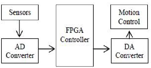
A robot capable of locomotion carries an FPGA board in charge of signal processing and control signal generation. Sensors send information to an analogical to digital converter and this information passes to the FPGA, when a control signal is generated, the information goes to a digital to analog converter that finally sends orders to the system motors according to Figure 1.
Figure 1 : Basic block diagram of system
An oscillator circuit is in charge of providing a 5 volts signal with a frequency of 50 KHz to the SRF05 ultrasound sensor, which is polarized with 5 volts dc. The SRF05 output is a 5 volts signal with a variable period that depends on the distance from the robot to the obstacle, this signal is treated to obtain a voltage value that is proportional to the distance to the object location. The figure 2 shows the sensor and its emission pattern
ISSN(Online): 2319-8753 ISSN (Print): 2347-6710
International Journal of Innovative Research in Science,
Engineering and Technology
(A High Impact Factor, Monthly, Peer Reviewed Journal) Visit: www.ijirset.com
Vol. 6, Issue 12, December 2017
In order to conditioning the input signal it is necessary to design the circuits for the oscillator, the converter from frequency to voltage, the analog to digital and digital to analog converters to interact with the FPGA. For the software, the input, output and control routines have been developed. The hardware design was planned as a modular system considering all the printed circuits, the coupling of stages, and the electrical signal conditioning [5-7].
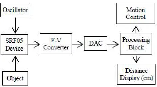
The software was developed considering that the robot includes two ultrasound transducers [8, 9], one in the frontal part and other one in the back part of the robot. Furthermore, the robot includes two infrared transducers, one placed on the right side and the other on the left one. The robot has been provided with two servomotors that control the course of the mobile. The software was developed using VHDL and the obtained results are adapted to the system requirements. A procedure for display the distance obtained by the FPGA board, measured in meters has been developed. Once frequency measured by the SRF05 is taken, the conversion of this frequency to the equivalent distance is programmed using a clock that counts the bits sent in a period. In order to take the distance between the mobile robot and the obstacle a range is used. If the distance is less than 20 cm several conditions are considered to calculate the distance. In this way it is possible to elude the obstacles and measure distance between objects and the mobile. A random function decides which direction must be taken, after verifying that no obstacles exist in more than 20 cm around. The voltage signal of 5 V in amplitude and variable period passes through one block that provides a linear voltage signal within a range of 0.02 and 5 volts. This voltage is converted to its correspondent digital equivalent. This signal is interpreted as the distance to the object. The prototype is intended to provide to the robot with the measured distance from where a certain obstacle is found in order to determine the actions that allow him to evade such an object, depending on the environment in which the robot is immersed. Figure 5 shows the block diagram for the data flow of the general system.
Figure 3 : Data flow diagram of the system.
IV.PROPOSED STRUCTURE
ISSN(Online): 2319-8753 ISSN (Print): 2347-6710
International Journal of Innovative Research in Science,
Engineering and Technology
(A High Impact Factor, Monthly, Peer Reviewed Journal) Visit: www.ijirset.com
Vol. 6, Issue 12, December 2017
Figure 3: Block diagram of proposed structure
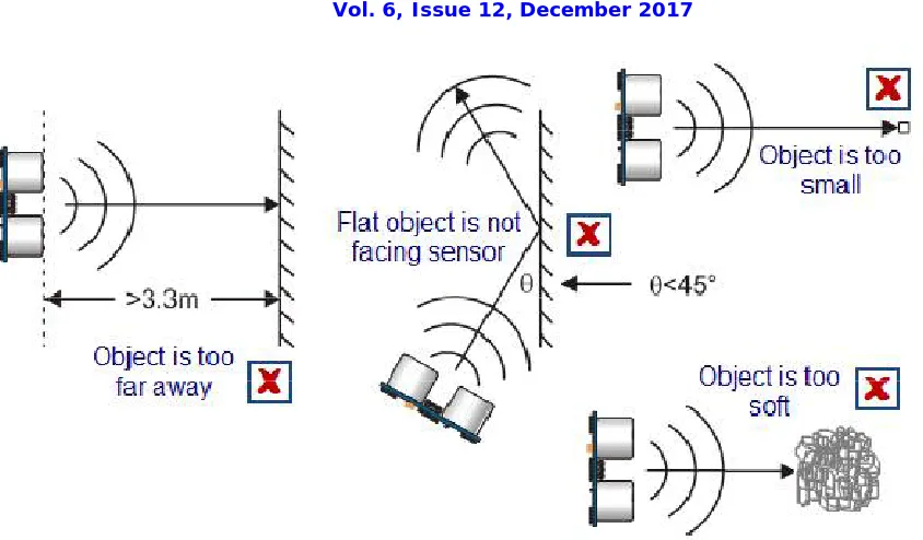
An infrared sensor is an electronic device, that emits in order to sense some aspects of the surroundings. An IR sensor can measure the heat of an object as well as detects the motion.These types of sensors measures only infrared radiation, rather than emitting it that is called as a passive IR sensor. Usually in the infrared spectrum, all the objects radiate some form of thermal radiations. These types of radiations are invisible to our eyes, that can be detected by an infrared sensor.The emitter is simply an IR LED (Light Emitting Diode) and the detector is simply an IR photodiode which is sensitive to IR light of the same wavelength as that emitted by the IR LED. When IR light falls on the photodiode, the resistances and these output voltages, change in proportion to the magnitude of the IR light received. An infrared sensor circuit is one of the basic and popular sensor module in an electronic device. This sensor is analogous to human’s visionary senses, which can be used to detect obstacles and it is one of the common applications in real time. A motor driver is an integrated circuit chip which is usually used to control motors in autonomous robots. Motor driver act as an interface between Altera cyclone II and the motors . The most commonly used motor driver IC’s are from the L293 series such as L293D, L293NE, etc. These ICs are designed to control 2 DC motors simultaneously. L293D consist of two H-bridge. H-bridge is the simplest circuit for controlling a low current rated motor. We will be referring the motor driver IC as L293D only. Ultrasonic sensor operates at
45
degree angle as well as in different conditions. The
ISSN(Online): 2319-8753 ISSN (Print): 2347-6710
International Journal of Innovative Research in Science,
Engineering and Technology
(A High Impact Factor, Monthly, Peer Reviewed Journal) Visit: www.ijirset.com
Vol. 6, Issue 12, December 2017
Figure 4: Ultrasonic operation in every condition
V.CONCLUSION
The developed system proposes the solution to the problem of determining and calculating distances thereby connecting extra module to the basic structure to enhance the application of the project. The electronic systems provide information to the mobile robot to give him autonomy in the decisions making process, which depends on the assigned task and the environment where the robot is immersed. The system includes a reprogrammable device in order to accelerate the application; this element provides enough flexibility for adjustment to new requirements or new algorithms.
REFERENCES
[1] T.Schlegl, T. Bretterklieber, M. Neumayer and H. Zangl, “A Novel Sensor Fusion Concept for Distance Measurement in Automotive Applications,” Graz University of Technology, Austria, 2010, pp. 755-778.
[2] JingZhuo Shi, “Ultrasonic motor motion control theory and technology,” Beijing: Science Press, 2011.
[3] Wenxiang Zhang, Zhijn Li and Zihong Zhang, “SCM system design and development of the tutorial,” Beijing: Electronic Industry Press, 2011. [4] R. A. Sigwalt, C. O. R. Negrão, and P. C. Tonin, Influência do Escoamentono Processo de Incrustação. Departamento Acadêmico de Mecânica, Centro Federal de Educação Tecnológica do Paraná, Seminário de Ciência e Tecnologia, 2002. (In Portuguese).
[5] J. L. Rose, “Recent advances in guided wave NDE,” in Proc. IEEE Ultrasoud. Symp., 1995, pp. 761–770.
[6] J. Barshinger, J. L. Rose, and M. J. Avioli, Jr., “Guided wave resonance tuning for pipe inspection,” J. Press. Vessel Technol., vol. 124, no. 3, Aug. 2002, pp. 310–330.
[7] Xilinx: http://www.xilinx.com
[8] Bates, M., Interfacing PIC microcontrollers, Newnes Edition, USA 2006. [9] Lovine J., PIC Microcontroller Project Book, Tab Books, USA, 2000.
107] Lovine J., PIC Robotics A Beginner’s Guide to Robotics Projects Using the PICmicro, McGraw- Hill, USA, 2004.
[11] K. R. Lohr and J. L. Rose, “Ultrasonic guided wave and acoustic impact methods for pipe fouling detection,” J. Food Eng., vol. 56, no. 4, Mar. 2003, pp. 315–324.