The 18thInternational Conference on Structural Mechanics in Reactor Technology (SMiRT18) Beijing, China, August 7-12, 2005 SMiRT18-B03-1
PHASE FIELD SIMULATION OF HYDROGEN DIFFUSION AND
HYDRIDE FORMATION PATTERN IN ZIRCONIUM
S.Q. Shi
1*, X.Q. Ma
2, X.N. Jing
1, X.H. Guo
1, L.Q. Chen
31
Department of Mechanical Engineering, The Hong Kong Polytechnic University
Hung Hom, Kowloon, Hong Kong, China
2
Department of Physics, University of Science and Technology Beijing
Beijing 100083, China
3
Department of Materials Science and Engineering, The Pennsylvania State
University, University Park, PA 16802, USA
ABSTRACT
γ-hydride precipitation and growth in zirconium were investigated using a phase-field kinetic model. The temporal evolution of the spatially dependent field variables is determined by numerically solving the time-dependent Ginzburg-Landau equations for the structural variables and the Cahn-Hilliard diffusion equation for the concentration variable. Elastic model, elastoplastic model and textured model were developed to simulate the morphology and microstructure evolution of the γ-hydride in zirconium. It is demonstrated that the morphology of hydrides is mainly determined by the stress distribution.
KEYWORDS:
diffusion, precipitation, phase field model, stress distribution, microstructure evolution1.
INTRODUCTION
For hydride forming metals and alloys, an important mechanism for hydrogen related fracture is due to the stress-induced formation and subsequent fracture of hydrides at stress concentrators. During service, these alloys are susceptible to a slow corrosion process that leads to a gradual pickup of hydrogen impurity from environment. Hydrogen in solid solution diffuses to the tensile region at flaws, such as blunt notches or sharp crack tips. If the hydrogen concentration in this region reaches the terminal solid solubility (TSS), hydrides will start to form and grow. Over a period of time, a complicated pattern of hydride precipitates can be developed around the tips of the flaws. Because of the brittleness of these hydrides, the original strength of the alloys can be reduced by orders of magnitude. When the flaw-tip hydrides reach some mysterious critical configuration, fracture through this hydrided region may occur. This phenomenon has been called delayed hydride cracking (DHC) and was observed directly by transmission electron microscopy for niobium [Mastsui 1987], titanium [Xiao 1987], vanadium [Takano 1974] and zirconium [Cann 1980] alloy systems. It is believed that the critical conditions for fracture initiation at hydrides are controlled by the morphology and microstructure of hydride precipitates at flaw tips [Eadie 1993, Shi 1994a,b, Dutton 1976a, 1994b]. Experimental results show that the morphology of hydride is controlled not only by the crystal structure and mechanical properties of hydrides, but also by the distribution and magnitude of the applied stress. Therefore, the dynamic evolution process of the morphology of hydrides and its relationship with the applied stress are among the most concerned problems to researchers.
1980, Shi 1994c]. We have studied the γ-hydride precipitation in single crystalline and bi-crystalline zirconium matrix under uniformly applied stress by phase-field kinetic method based on Khachaturyan’s elastic theory [Ma 2002a, 2002b, 2002c]. Our early phase field model can predict very well the evolution of arbitrary hydride precipitation pattern under uniformly applied stress, and it includes the interaction between hydrides (many-body effect). However, materials used in engineering are often polycrystalline with or without texture, and under non-uniformly applied stress, such as stress concentrations. Another important factor ignored before is the plastic deformation during phase transformation. The volume expansion during hydride formation is about 15%, which is beyond the elastic limit of zirconium. In addition, plastic deformation is inevitable at those sharp notch or crack tip where the stress level is already very high. When the grain size is much smaller than the average size of hydrides, a continuum medium may be assumed. The objective of this work is to develop a phase field model that can account for non-uniformly applied stress and plastic deformation during hydrogen diffusion and γ -hydride precipitation. In section 2, the linear elastic phase field model for a continuum medium will be developed first, followed by a brief description of a newly developed elastoplastic phase field model. Methods to handle texture formation will also be discussed. In section 3, a comparison between linear elastic and elastoplastic models will be given first for single crystalline zirconium, followed by some preliminary results on hydride formation in a textured system. Then a treatment for a continuum elastic medium is given, which leads to some preliminary results on hydride precipitation at a blunt notch where the applied stress is relatively low. Our long-term objective is to combine the methodologies developed so far into one complete package that includes plasticity as well as non-uniformly distributed stress for a continuum medium, or a highly textured material.
2. THE PHASE-FIELD MODEL FOR SECOND-PHASE PRECIPITATION
2.1 The elastic model
In a homogeneous continuum system, the effects of anisotropic properties of the crystalline grains on the precipitation are neglected. In this case, the orientation of the precipitates is determined by the applied stress field. To simulate this situation, a multi-variant system, which can represent the structure change of the precipitates growing along any direction in the specimen, needs to be constructed. We use the long range order (lro) parameter,ηp , to denote the structure of pth variant of hydrides. The more lro the system has, the more accurate it will be to simulate an isotropic system. The hydrogen concentration in the matrix and precipitates is still described by a conserved field variable, c(r,t).
In the phase-field model, both the diffusion of the hydrogen atom and precipitation of the hydride are considered simultaneously. The temporal evolution of the composition is determined by the Cahn-Hilliard diffusion equation [Cahn 1958]
( , )
( , ) ( , )
c r t F
M r t
t c r t
δ
ξ
δ
∂
= ∇ ⋅ ∇ +
∂ (1) and the temporal evolution of microstructure is determined by the time-dependent Ginzburg-Landau equations [Allen 1979]
( , )
( , ) ( , )
P
p p
p
r t F
L r t
t r t
η δ ς
δη ∂
= − +
∂ (p = 1, 2, 3, …) (2) where L and M are kinetic coefficients characterizing structural relaxation and diffusion mobility and may be obtained from experimental measurements. F is the total free energy of the system; ζp(r, t) and ξ(r, t) are
Langivin random noise terms that are related to fluctuations in the long range order parameter and composition respectively. The noise terms satisfy Gaussian distribution and meet the requirement of the fluctuation– dissipation theorem [Landau 1980].
In equations (1) and (2), the driving force for the temporal evolution of a multiphase microstructure comes from the reduction of the total free energy of the system which consists of four major contributions: 1) chemical free energy due to phase transformation; 2) the interfacial energy between hydrides and matrix; 3) the strain energy caused by the lattice mismatch between the matrix and precipitates; and 4) the interaction energy between the stress free strains (of hydrides and hydrogen atoms) and external load. If we combine 1) and 2) as the total chemical free energy of a chemically inhomogeneous system Fc; 3) and 4) as the elastic energy Eel, then
F=Fc+Eel (3)
(
)
2 2 3 4 61 2 4
1 2
2 2 4 2 2 2 2 2
5 6 7
,
( , ) ( )
2 2 4 6
( )
p p p p
p p p
p q p q r p q r
q p p q p r p q r
A
A A A
c c c c c
A A A
f ν ν ν ν ν ν η η η η η η η η η η η η ≠ ≠ ≠ ≠ ≠ = − + − − + + + + +
∑
∑
∑
∑
∑
∑
(4)The interfacial energy between different phases can be expressed through the gradient terms in c and η. The total chemical free energy of a chemically inhomogeneous system may be expressed as [Cahn 1958].
2 2 3
1
( , ( )) ( ( )) ( )
2 2
p
c v p p
p
F f c r r c d r
ν α β
η η
=
=
⎡
⎢
+ ∇ + ∇⎤
⎥
⎣
∑
⎦
∫
(5)Since the expansion misfit strain of a γ-hydride causes an additional stress field and may interact elastically with the hydrogen atoms and other hydrides nearby, the diffusion process of the hydrogen atoms in the matrix and, furthermore, the precipitation of other hydrides nearby may be affected. Hence, the influence of stress fields on the precipitation process of hydrides should be considered. In the stress constraint condition, the elastic energy can be expressed as follows:
∫
∫
∫
∫
∫
∑
∑
∫
∫
−
−
Ω
−
−
=
−
−
−
−
=
−
−
=
= = V ij appl ij appl kl appl ij ijkl l kl jk ij i V V kl V ij ijklV ijkl ij kl
c kl p p kl kl c ij p p ij
v ijkl ij
kl kl ij
v ijkl ij
el
r
d
r
S
V
g
d
n
g
n
g
n
r
d
r
r
d
r
C
V
r
d
r
r
C
r
d
r
c
r
p
r
c
r
p
C
r
d
C
E
3 0 3 * 0 0 3 3 0 3 0 3 0 0 3 3 1 2 3 1 2 3 0 0)
(
2
)
(
~
)
(
)
(
~
)
2
(
1
2
1
'
)
'
(
)
(
2
1
)
(
)
(
2
1
)]
(
)
(
)
(
[
)]
(
)
(
)
(
[
2
1
)
(
)
(
2
1
ε
σ
σ
σ
σ
σ
π
ε
ε
ε
ε
δ
ε
η
ε
ε
δ
ε
η
ε
ε
ε
ε
ε
ε
η η (6)where
(
)
(
)
(
)
(
)
3 1 2 0
r
c
r
p
r
c ij p p ijij
ε
η
ε
δ
ε
=
∑
η+
=
;
σ
applis applied stress;ε
ijcis the stress-free strain caused byhydrogen atom;
ε
ijηis the stress-free strain of the hydride;σ
ijcandσ
ijη are stresses induced by the solutehydrogen atom and the hydride, respectively;
C
ijklis the elastic constant tensor; g is the reciprocal vector and g is the amplitude of g;n=g /g; andΩ
−jk1(
n
)
=
n
iC
ijkln
l; c(g) and {η(r)}g are the Fourier transformation of c(r)
and η(r) respectively; and { }* is the complex conjugate of { }.
The strain at a point
r
generated by stress-free transformation strains can be calculated by Khachaturyan theory :
[
(
)
(
)]
~
(
)
exp(
)
)
2
(
2
1
)
(
)
(
3 03 0
r
g
⋅
Ω
+
Ω
+
+
=
r
S
∫
d
g
n
n
n
n
g
n
i
r
ij ijkl klappl i jk j ik kl lij
ε
σ
π
σ
ε
(7)
=
∫
V ij
ij
r
d
r
V
3 0 0)
(
1
ε
ε
ij
r
C
ijkld
g
n
k lmn
n
l kmn
σ
mng
n
ni
ε
klr
ε
klr
σ
ijapplπ
σ
⎥
+
⎦
⎤
⎢
⎣
⎡
+
−
⋅
Ω
+
Ω
=
∫
[
(
)
(
)]
~
(
)
exp(
)
(
)
(
)
)
2
(
2
1
)
(
3 0 0 03
r
g
(8)where ( )
2 (1 )
ij i j ij n n G G
δ
ν
Ω = − −n , in which G is the shear modulus and ν is the Possion’s ratio. In this model,
we take the homogeneous hydrogen distribution state as the reference state, which leads to the same result as in the hydrogen-free state in the liner elastic range. This condition is maintained when the hydrogen concentration in solid solution is low. It should be noticed that these expressions of elastic energy have included the interactions between hydrides, between H atoms in solid solution, between hydrides and H atoms, between the applied stress and hydrides, and between the applied stress and H atoms.
2.2 The elastoplastic model
It can be found from the elastic model that equivalent stress around hydride tips exceeds yield stress of zirconium; therefore the assumption of linearly elastic deformation is not exact. The elastic phase field model should be modified. Since many zirconium alloys deform in an elastic-perfectly plastic fashion (see Fig. 1), we developed an elastoplastic phase field model based on the elastic perfectly plastic constitutive relation to account for the effect of plasticity.
In classical metal plasticity theory, the yield stress (σY) is independent of hydrostatic stress. Von-Mises
equivalent stress is given by
[
2 2 2]
2 2 22 2
3
3
3
)
(
)
(
)
(
2
1
2
3
3
zx yz xy xx zz zz yy yy xx ij ij sJ
σ
σ
σ
σ
σ
σ
σ
σ
σ
σ
σ
σ
+
+
+
−
+
−
+
−
=
′
′
=
′
=
(9)For plane strain
σ
zz=
ν
(
σ
xx+
σ
yy)
[
2 2 2]
22
3
)
(
)
(
)
(
2
1
xy xx zz zz yy yy xxs
σ
σ
σ
σ
σ
σ
σ
σ
=
−
+
−
+
−
+
(10)The yield criterion is when
σ
s=
σ
Y. We define a yield potential[
2 2 2]
2 2 2 23
3
3
)
(
)
(
)
(
2
1
Y zx yz xy xx zz zz yy yy xx YF
=
σ
−
σ
+
σ
−
σ
+
σ
−
σ
+
σ
+
σ
+
σ
−
σ
Based on strain energy relations, the yield criterion in isotropic media can also be written as
G
E
F
Y el Y6
2σ
−
′
=
where
E
el′
is the distortion strain energy. It is expressed below for a continuum medium:[
][
]
appl ij appl ij v ij appl ij l kl jk ij i v ij v ij ij v ij ij ijv ij ij
where eij is the deviatoric strain and it is given by
ij kk ij
ij
e
ε
ε
δ
3
1
−
=
. The major difficulty in developingsuch an elastoplastic model is associated with the presence of arbitrary-shaped plastic zone, which requires an accurate determination of the equilibrium strain. To address this question, the distributed plastic strain
ε
ijpisassumed nonzero only within arbitrary shaped plastic zones and zero outside plastic zone as field variables.
We add a new term in the whole stress-free strain, such that
)
(
)
(
)
(
)
(
0r
r
r
r
ij ijc ijpij
ε
ε
ε
ε
=
η+
+
, and assume that the effective
stress-free strain of plasticity satisfies a time-dependent Ginzburg-Landau Equation
)
,
(
)
,
(
)
,
(
t
r
E
K
t
r
F
K
t
t
r
plas p kl el ijkl plas p kl Y ijkl plas p ijδε
δ
δε
δ
ε
′
−
=
−
=
∂
∂
(12)And k lm l km mn n igr kl kl klappl
plas p kl el
s
e
r
e
e
n
g
s
n
n
n
n
g
d
t
r
E
−
⎥
⎦
⎤
⎢
⎣
⎡
+
−
Ω
+
Ω
−
=
′
∫
0 ⋅ 0 03 3
)
(
)
(
~
)]
(
)
(
[
)
2
(
2
1
2
)
,
(
μ
π
δε
δ
(13)The above equations are only applied within the plastic zone. A convenient choice for
K
ijkl isK
ijkl=
KC
ijkl−1 for simplicity. Because the stress equilibrium is established much faster than the microstructure evolution, K is chosen as a number larger than constants L and M. The deviatoric stressappl ij ij ij r ig n mn im j jm i
ij
n
n
n
n
s
g
n
e
e
r
e
s
g
d
r
s
⎥
+
⎦
⎤
⎢
⎣
⎡
+
−
Ω
+
Ω
=
∫
0 ⋅ 0 03 3
)
(
)
(
~
)]
(
)
(
[
)
2
(
2
1
2
)
(
π
μ
(14)Now the equation (12) changes to
kl ijkl plas p ij
s
K
t
t
r
=
∂
∂
ε
(
,
)
. (15)
which is similar to the classical Prandtl-Reuss theory
ij ij
p
ij
d
s
F
d
d
λ
σ
λ
ε
=
∂
∂
=
(16)The temporal evolution of hydrogen diffusion and hydride growth are determined by solving the time-dependent Cahn-Hilliard diffusion equation for
c
(
r
)
and Ginzburg-Landau equations forη
p(
r
,
t
)
and)
,
(
r
plast
p ij
ε
. As shown in the following section, the numerical solutions ofc
(
r
,
t
)
,η
p(
r
,
t
)
and)
,
(
r
plast
p ij
ε
from these kinetic equations automatically take into account the effects of elastoplastic deformation and describe hydrogen diffusion and hydride morphology evolution without a priori assumption of the shapes of hydrides and plastic zones.2.3 Grain growth with texture
σ
p
ε
ε
eε
Fig.1. Schematic of the stress vs strain relation.
p
Materials in the applications are often polycrystalline and have texture due to processing. In this work, by adding an orientation dependant probability term to a phase-field model for grain growth (Chen, 1995), the texture was obtained. The model is described as follows.
The microstructure, i.e. the orientation of each crystal grain, is described by a set of continuous phase-field variables η1,η2, …ηp. The grain growth is driven by the reduction of the total free energy of the system. The
total free energy of an inhomogeneous system containing grain boundaries is given by
∫
∑
⎥⎦ ⎤ ⎢
⎣ ⎡
∇ +
+
= 2 3
2 1
0 ( ( ))
2 )) ( )... ( ) (
(( r r r r dr
f F
F i
i
p η
κ η
η
η ,
where f (…) is the local free energy density and
∑
∑∑
= =
=
+ +
= μ αη βη γ μ η η η
η η
1 1
2 2 4
1 2 2
1 )
4 2 ( ) ,..., , (
i p
j j i i
i i p
f , ηp are field
variables, p is the number of the field variables, and κi are the gradient energy coefficients. The gradient energy
terms give rise to grain boundary energies. The migration kinetics of the field variables are described by Ginsberg-Landau equations
) ( )
, (
r F L dt
t r d
i i
i ξ
δη δ η
+ −
= , i=1,2, …p
where Li are the kinetic coefficients which describe the grain boundary mobility. ξ( r) is a noise term to mimic
the nucleation process at the initial stage. To obtain a texture structure, we assume that ξ(r) is a function of the
spatial direction of each grain with the normal distribution, i.e. 2 2
2 ) 90 ) 180 , (mod(
2 1 )
( σ
θ
πσ ξ
− −
= e
r . The dynamical
equation is solved by the Eular’s finite different method.
3. SIMULATION RESULT
3.1
γ
-hydride precipitation in single crystalline material simulated by elastic and
elastoplastic phase-field models
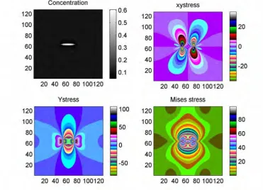
To simulate the shape evolution of a single hydride particle and stress distress distribution around it, we put a spherical particle at the center of a 128
×
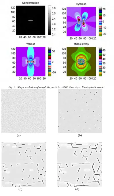
128 grid. The initial concentration of hydrogen was set to be 0.6 at%. The equilibrium concentration of hydrogen in the zirconium matrix and γ-hydride are obtained from the phase diagram of the zirconium-hydrogen system [Bardbrook 1972]. Both the elastic and plastic models were used to simulate the shape evolution without using the noise terms. In both models, the initial spherical hydride evolved into a needle-like particle. The shape change is due to the crystallographical anisotropy of transformation strains of the hydride. The morphology of a coherent precipitate is actually determined by the balance between the strain energy and interfacial energy. Since the interfacial energy was assumed to be isotropic, the shape change here is mainly determined by the strain energy, which is a function of stress-free strains of the hydride. By comparing the results from the elastic and elastoplastic models, we found that the stress level in the elastoplastic model is lower than that in the elastic model (see figure 2 and figure 3). This was caused by the stress relaxation around the hydride through plastic deformation. A detail analysis showed that a plastic zone around the hydride was developed in the elastoplastic model, which caused a lower hydrogen concentration around the hydride than that in the elastic model.In order to simulate the complete phase transformation process that includes nucleation and growth, we applied the noise terms in equations (1) and (2) to mimic the thermo-fluctuation during phase transformation. The initial value of C0(r, t) was set to be 0.6 at%, ηp(r, t) to be zero, and two noise terms in equations (1) and (2) were
(200MPa here), the hydrides align themselves perpendicular to the tensile direction. This is also in excellent agreement with experimental observations.
3.2 Grains growth with texture and hydrides precipitation
Using the method described in section 2.3 and adopting 36 long-range order parameters to represent 36 different crystal orientations, we simulated a grain growth process. In the simulation, α, β equal to 1, κi equal to 2
respectively. Time step dt is 0.004, σ is 4. The noise term was turned on at the first 1000 time step to form the nuclei of the grain. Under the driven of the total free energy, the grains grow up from the nuclei and the coarsening process could be observed in the growth process. The advantage of this method is that it produces the microstructural evolution automatically without tracking the position of grain boundaries. The morphology of the grain is a natural result of solving the dynamical equation.
By adding an orientation dependent random term, a polycrystalline structure with texture is simulated. Figure 6 is the morphology of the system at the different time stage. One may clearly see that in the coarsening process, the smaller grains shrink and larger ones grow up. It can also be seen in figure 6 (b) that the orientation of the <1120> direction is near the y-axis. By using the multi long-range order parameters, as described in ref (Ma, Shi 2002b), we simulated the γ-hydride precipitation in the above textured polycrystalline system. In order to see clearly, we only turned on one lro along [1120], the result shows that precipitate in each crystal nearly parallel with the y-axis.
3.3
γ
-hydride precipitation in continuum media simulated by elastic phase-field model
Most engineering materials are polycrystalline. When the grain size is small as compared to the hydride size, the material may be considered as a continuum medium. The effects of anisotropic properties of the grains on the precipitation may be neglected. In this case, the orientation of the precipitates is determined by the applied stress field. To simulate this situation, a multi-variant system, which can represent the structure change of the precipitates grown along any direction in the specimen, is constructed. We use the long range order (lro) parameter,ηp, to represent the structure of pth variant of the hydride. The more lro the system has, the more accurate it would be for an isotropic system. The hydrogen concentration in the matrix and precipitates is still described by a conserved field variable, c(r,t). To simplify the calculation, we consider linear elastic strain energy only.
Fig. 3. Shape evolution of a hydride particle. 10000 time steps. Elastoplastic model.
(a) (b)
Fig.4 Simulated precipitation process of γ-hydrides in a hexagonal zirconium matrix, 512×512 uniform grid, (a) t*=1000, (b) t*=2000, (c) t*=4000, (d) t*=6000.
Fig.5. Morphology of hydrides under uniformly applied stress of 200MPa along vertical direction. The number of grid point is 128
×
128.(a) (b)
Fig.6 Simulation result of grain growth with phase-field model. (a) t=10000, (b) t=500000 The numbers in (b) represent the angle between the <1120> and x-axis.
Fig. 8. Simulation result of γ-hydride Fig. 9. Optical micrograph image of precipitation under a uniform applied γ-hydride precipitation under applied stress of 200 MPa along y direction tensile stress along y direction
We simulate two cases: In case 1, a uniform tensile stress was applied along the direction of y-axis. When the stress reaches 200 MPa, as seen in figure 8, the result shows that most of γ-hydrides precipitate perpendicular to the direction of the applied stress. This is consistent with the observation made in the experiment, figure 9. Since the γ-hydride has a much smaller expansion misfit strain in the needle-axis direction, it creates lower elastic energy when grown along the direction perpendicular to the tensile stress. Therefore, the γ-hydrides grow in the form of parallel chains perpendicular to the direction of applied tensile stress.
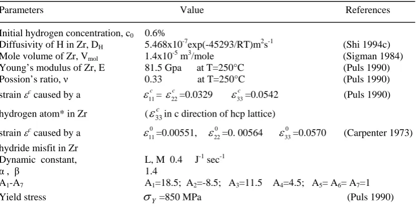
Table 1. Parameters used in the calculation
Parameters Value References
Initial hydrogen concentration, c0 0.6%
Diffusivity of H in Zr, DH 5.468x10⁻⁷exp(-45293/RT)m2s-1 (Shi 1994c)
Mole volume of Zr, Vmol 1.4x10⁻⁵ m3/mole (Sigman 1984)
Young’s modulus of Zr, E 81.5 Gpa at T=250°C (Puls 1990) Possion’s ratio, ν 0.33 at T=250°C (Puls 1990) strain εc caused by a
ε
11c=ε
22c =0.0329ε
33c =0.0542 (Puls 1990)hydrogen atom* in Zr ( 33 c
ε
in c direction of hcp lattice)strain εc caused by a
ε
110=0.00551,ε
220 =0. 00564ε
330 =0.0570 (Carpenter 1973) hydride misfit in ZrDynamic constant, L, M 0.4 J-1 sec-1
α , β 1.4
A1-A7 A1=18.5; A2=-8.5; A3=11.5 A4=4.5; A5= A6= A7=1
Yield stress
σ
Y =850 MPa (Puls 1990)* Values are for the hydrogen isotope, deuterium.
In case 2, we investigate the hydrogen diffusion and hydride precipitation near a notch or a crack tip. The system was built up as follows: a cantilever specimen is made of zirconium full of uniformly distributed dilute hydrogen in solid solution. A notch with a flank angle of 45o and a depth d was cut at the center of upper edge. The root radius of the notch tip is 0.3 mm. One end of the specimen was fixed horizontally and a dead weight load of 50 N was applied on the other end to generate a non-uniform tensile stress at the area around the notch. The commercial finite element (FE) software, NASTRAN, was used to calculate stress distribution. The average mesh size in the area around the notch is 0.03mm. The stress distribution around the notch is shown in figure 10a and figure 10b. The result shows that there is a high hydrostatic tensile stress zone in front of the notch tip. The isostress lines for hydrostatic stress are close to round shape. The gradient of the stress near the notch is the driving force for hydrogen diffusion. The stress distribution from NASTRAN was adopted as an applied stress in the calculation of hydrogen diffusion and γ-hydride precipitation in the phase field model.
(a) (b)
Fig.10. Stress caused by applied load around the notch, the unit is in MPa. (a) σxx (b) hydrostatic stress
Phase field method is used to calculate the pure diffusion process. The result is shown in figure 11 for the distribution of hydrogen concentration near the notch region (calculation procedure will be published in a separate report [Ma, in press]).
The phase field method was used again in a precipitation simulation. Here, 12 lro were adopted. The angle difference between the two successive variants was 15º. The non-uniform stress distribution from FE calculation and equilibrium hydrogen concentration after diffusion were input as the applied stress and initial concentration.
Other parameters used in the calculation are those listed in table 1. The Cahn-Hilliard equation (1) and the time-dependent Ginzburg-Landau equations (2) were solved by Fourier spectrum method. In the calculation, the mobility M inside the notch area was set zero and noise terms were turned on in the first 1000 time step to represent the thermal fluctuation as in the calculation for the uniform applied stress condition.
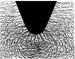
Figure 12 is the simulation result. It can be seen that 1) the density of the hydride precipitates at the notch tip area is higher than that in other areas; 2) the hydrides precipitate in the direction perpendicular to the notch surface at the notch boundary. This is harmful to the safety because the hydrides may cause the initiation and propagation of cracks;
Fig.12. Phase-field simulation result of γ-hydride Fig.13. Optical micrograph of hydrides precipitated around a notch in a loaded cantilever precipitated around a notch in a loaded
cantilever
3) the hydrides in the area away from the notch tip form a circular like shape. The morphology pattern obtained from the simulation is similar to experimental result given in figure 13. The difference between figure 12 and figure 13 is significant, because the experimental result was obtained at a much higher stress level that resulted in plastic deformation around the notch tip. The elastoplastic methodology will be used in this case in future study. A new phase field method to account for crack initiation and propagation process will be developed in the near future so that the whole DHC process can be modeled and its mechanism could be better understood.
x
y
ACKNOLEDGEMENTS
This work was funded by a research grant from Research Grant Council of Hong Kong (B-Q471) for Shi, Jing and Guo, from Hong Kong Polytechnic University (G-V851) for Ma, and from the U.S. National Science Foundation (DMR 96-33719) for Chen.
REFERENCES:
S.M. Allen and J.W. Cahn, (1979), Acta Metal., vol.27 , pp.1085
J.S. Bardbrook, G.W.Lorimer and N. Ridley, (1972), J. Nucl. Mater., vol.42, pp.142 J.W. Cahn and J.E. Hilliard, (1958),J. Chem. Phys., vol. 28, pp.258
C.D. Cann and E.E. Sexton, (1980), Acta Metall., vol.28, pp.1215. G.J. Carpenter, (1973),J. Nucl. Mater. vol.48, pp.264
L.Q. Chen and Y.Wang, (1996), Journal of Metals vol.48, pp.11 L.Q. Chen, (2002), Annu. Rev. Mater. Res. vol. 32, pp.113
R. Dutton and M.P.Puls, (1976), in “Effect of hydrogen in Behavior of Materials’, ed. By A.W.Thompson and I. M. Bernstein, TMS-AIME, New York, pp.516.
R.L. Eadie, D.R. Metzger and M. Leger, (1993),Scr. Metall., vol.29, pp.335
L.D Landau and E. M. Lifshitz, (1980), Statistical Physics, Part 1, Pergamon Press, London.
A. G. Khachaturyan (1983)Theory of Structural Transformation in Solids, John Wiley& Sons, New York. X.Q. Ma., S.Q. Shi, C.H. Woo and L.Q. Chen, (2002a), Comp. Mater. Sci. vol.23, pp.283
X.Q. Ma., S.Q. Shi, C.H. Woo and L.Q. Chen, (2002b), Scr. Mater., vol. 47, pp.237 X.Q. Ma., S.Q. Shi, C.H. Woo and L.Q. Chen, (2002c), Mat. Sci. Eng. A, vol.334, pp.6 S.R. MacEwen, C.E. Coleman, C.E.Ells, J. Faber, (1985), Acta Metall. vol.33, pp.753 H. Mastsui, N. Yoshikawa and M. Koiwa, (1987), Acta Metall., vol. 35, pp.413 W. J. Pardee and N.E. Paton, (1980), Metall.Trans. A., vol.11A, pp.1391. M.P. Puls, (1990),Metall. Trans. A . vol. 21, pp.2905
S.Q. Shi and M.P. Puls, (1994a), J. Nucl. Mater., vol.208, p.232.
S.Q. Shi, M.P. Puls and S. Sagat, (1994b), J. Nucl. Mater., vol.208, p.243.
S.Q. Shi, M. Liao and M.P. Puls, (1994c), Modelling Simul. Mater. Sci. Eng., vol.2, pp.1065. C.N. Singman, (1984) .J. Chem. Edu. vol.61, pp.137
S. Takano and T. Suzuki, (1974), Acta. Metall., vol.22, pp.265.