Scholarship@Western
Scholarship@Western
Electronic Thesis and Dissertation Repository
8-19-2013 12:00 AM
High density gas-solids circulating fluidized bed riser and downer
High density gas-solids circulating fluidized bed riser and downer
reactors
reactors
Chengxiu Wang
The University of Western Ontario
Supervisor Dr. Jesse Zhu
The University of Western Ontario Joint Supervisor Dr. Shahzad Barghi
The University of Western Ontario
Graduate Program in Chemical and Biochemical Engineering
A thesis submitted in partial fulfillment of the requirements for the degree in Doctor of Philosophy
© Chengxiu Wang 2013
Follow this and additional works at: https://ir.lib.uwo.ca/etd
Part of the Catalysis and Reaction Engineering Commons, Petroleum Engineering Commons, and the Transport Phenomena Commons
Recommended Citation Recommended Citation
Wang, Chengxiu, "High density gas-solids circulating fluidized bed riser and downer reactors" (2013). Electronic Thesis and Dissertation Repository. 1572.
https://ir.lib.uwo.ca/etd/1572
This Dissertation/Thesis is brought to you for free and open access by Scholarship@Western. It has been accepted for inclusion in Electronic Thesis and Dissertation Repository by an authorized administrator of
DOWNER REACTORS
(Thesis Format: Integrated-Article)
By
Chengxiu Wang
Graduate Program in Chemical and Biochemical Engineering
A thesis submitted in partial fulfillment
of the requirements for the degree of
Doctor of Philosophy
The School of Graduate and Postdoctoral Studies
The University of Western Ontario
London, Ontario, Canada
ii
A systematic and comprehensive study of hydrodynamics and reactor performance was conducted in a 76 mm i.d., 10 m high riser and a 76 mm i.d., 5.8 m high downer reactor under high density/flux operating conditions using fluid catalytic cracking (FCC) catalyst particles. An optical fiber probe was used to obtain a complete mapping of local solids holdup and particle velocity. Catalytic ozone decomposition reaction was employed to study the characteristics of reactor performance in the CFB riser and downer. The superficial gas velocity (Ug) and the solids
circulation rate (Gs) were 3-9 m/s and 100-1000 kg/m2·s, respectively. Based on the spatial
distributions of catalyst particles and gas reactant in the riser and the downer, hydrodynamics and reactor performance were fully characterized.
Solids suspension having a solids holdup of up to 0.2-0.3 could be maintained throughout the entire high flux/density riser. A homogenous axial flow structure was observed at Gs = 1000
kg/m2s. When Gs exceeded about 800 kg/m2s, the axial profile of the particle velocity became
more uniform. The axial particle velocity was affected more significantly by high superficial gas velocity especially under high solids flux/density conditions. No net downward flow near the wall was one of the most important advantages of the high flux/density riser over the conventional low flux/density reactor, leading to a reduction of solids backmixing. Radial distributions of the solids holdup were nonuniform with a dilute region and a dense region. When
Gs was higher than 700 kg/m2s, the dilute core region shrank to less than 20% of the
cross-sectional area. Solids holdups thereafter increased monotonically towards the wall which could be up to 0.59. Moreover, solids holdup remained higher than 0.4 over a wide cross-sectional area (r/R = 0.7-1.0, about 60% of the cross-sectional area) even at the top section of the riser. Radial distribution of solids holdup in the downer was much more uniform than that in the riser. Radial profiles of solids holdup were characterized by a flat value covering a wide region of the cross section and a relatively high value near the wall in the fully developed section. The uniform distribution of solids flow provided a nearly plug flow condition in the downer reactor.
iii
indicated that ozone reaction in the CFB reactors was controlled by the gas-solids flow structure. Strong interrelation was observed between the distributions of solids and reactant concentration. Higher solids holdups would give higher ozone conversions. Most conversion occurred in the entrance region, that is, the flow developing zone of the riser and downer reactors. Overall ozone conversions in CFB riser and downer deviated from plug-flow behavior indicating that hydrodynamics affected CFB reactor performance. The extent of the deviation of the conversion could be attributed to the different gas-solids contacting efficiency.
Keywords: Circulating fluidized bed riser/downer, high density, high flux, hydrodynamics,
iv
Chapter 4: Hydrodynamics in a high density CFB riser-Solids holdup and flow development
Authors: Chengxiu Wang, Jesse Zhu, Shahzad Barghi, and Chunyi Li
Chengxiu Wang carried out the experiments and data analysis under the guidance of Dr. J. Zhu and Dr. S. Barghi and in consultation with Dr. C. Li. All experimental work was conducted by Chengxiu Wang and the draft of this manuscript was written by Chengxiu Wang. Revisions were carried out under the close supervision of three advisors, Drs. J. Zhu, S. Barghi and Dr. C. Li. The final version was submitted to AIChE Journal.
Chapter 5: Hydrodynamics in a high density CFB riser-Particle velocity and solids flux
Authors: Chengxiu Wang, Jesse Zhu, Shahzad Barghi and Chunyi Li
Chengxiu Wang carried out the experiments and data analysis under the guidance of Dr. J. Zhu and Dr. S. Barghi and in consultation with Dr. C. Li. All experimental work was conducted by Chengxiu Wang and the draft of this manuscript was written by Chengxiu Wang. Revisions were carried out under the close supervision of three advisors, Drs. J. Zhu, S. Barghi and Dr. C. Li. The final version was submitted to the journal Chemical Engineering Science.
Chapter 6: Hydrodynamics in a high flux CFB downer
Authors: Chengxiu Wang, Shahzad Barghi, Jesse Zhu and Chunyi Li
Chengxiu Wang carried out the experiments and data analysis under the guidance of Dr. J. Zhu, Dr. S. Barghi and in consultation with Dr. C. Li. All experimental work was conducted by Chengxiu Wang and the draft of this manuscript was written by Chengxiu Wang. Revisions were carried out under the close supervision of three advisors, Drs. J. Zhu, S. Barghi and C. Li. The final version is ready for submission to Chemical Engineering Journal.
Chapter 7: Catalytic ozone decomposition in a high density gas-solids CFB riser
v
advisors, Dr. J. Zhu and Dr. S. Barghi. Dr. G. Wang assisted in some key experimental work. All experimental work was conducted by Chengxiu Wang and the draft of this manuscript was written by Chengxiu Wang. Revisions were carried out under the close supervision of two advisors, Drs. J. Zhu and S. Barghi. The final version is ready for submission to the journal Chemical Engineering Science.
Chapter 8: Catalytic ozone decomposition in a high flux gas-solids CFB downer
Authors: Chengxiu Wang, Shahzad Barghi and Jesse Zhu
vi
This work is dedicated to my maternal grandparents and my mother.
vii
The completion of this degree would not have been possible if it were not for those people who truly believed in my potential and provided me with opportunities; who landed help whenever I needed; and who unconditionally supported me. I would like to thank the many people, supervisors, instructors, family and friends, who helped me to reach this level of achievement.
I would like to express my deepest gratefulness to my chief supervisor Dr. Jesse Zhu for his encouragement, guidance, inspiration and continuous support throughout this endeavor. He encouraged me and challenged me every step of the way, professionally and personally, allowing for my own developments. His meticulous supervision not only ensured the successful fulfillment of this study but also brought great improvement to my comprehensive skills, which is invaluable for me to enjoy forever.
Much appreciation is extended to my co-supervisor Dr. Shahzad Barghi for his helpful guidance, constructive suggestions, kind encouragement during the progress of this work, generous timely support and for carefully going through the manuscripts and making the text more readable.
My special thank you is directed to Dr. Chunyi Li, my co-supervisor on China size, at China University of Petroleum, for his inspirational knowledge and providing me this excellent opportunity for coming to Canada to complete my degree. Many thanks also go to his wife Mrs. Guifen Yin for her great help during those years when I was in China.
I would like to thank Mr. Jianzhang Wen and Mr. Michael Zhu for their help in maintaining the experimental unit, and visiting professor Gang Wang for his help with some of the ozone decomposition tests. Thanks go to George Zhang, Joanna Blom, April Finkenhoefer, Kristen Hunt, Lisa Desalaiz, Mike Gaylard, Clayton Cook for their help and supports.
viii
through our interactions. Thanks also go to all members of the research group, Mrs. Ying Ma, Dr. Hui Zhang, the visiting professor, Dr. Hong Chen and many others for all the help, advice and friendship.
I would like to express my most sincere gratitude to my friends Ms. Huan Gao in the Department of Statistical and Actuarial Sciences, Western University and Mr. Guangbin Sun in the School of Computer Science, Carnegie Mellon University, for their invaluable encouragement and unconditional support throughout these years of sacrifice and hard work.
ix
ABSTRACT ... ii
CO-AUTHORSHIP ... iv
DEDICATION ... vi
ACKNOWLEDGEMENT ... vii
TABLE OF CONTENTS ... ix
LIST OF TABLES ... xvi
LIST OF FIGURES ... xvii
CHAPTER 1 Introduction... 1
1.1 Background ... 1
1.2 Research objectives ... 4
1.3 Thesis structure ... 4
References ... 6
CHAPTER 2 Literature Review ... 9
2.1 Introduction ... 9
2.2 Hydrodynamics in CFB riser ... 11
2.2.1 Axial profiles of solids concentration ... 12
2.2.2 Radial profiles of solids concentration and particle velocity ... 15
2.3 Effects on the flow structure ... 18
x
2.3.3 Riser geometry effect ... 19
2.4 Hydrodynamics in CFB downer ... 20
2.4.1 Three-section axial flow structure ... 22
2.4.2 Radial gas and solids flow structure ... 24
2.5 Ozone decomposition in CFB reactors ... 31
2.5.1 Experimental researches with ozone decomposition ... 31
2.5.2 Ozone decomposition in the CFB riser reactor ... 35
2.5.3 Ozone decomposition in the CFB downer reactor ... 38
2.5.4 Contact efficiency of ozone decomposition reaction ... 41
2.6 Conclusions and outlook ... 43
Nomenclature ... 45
References ... 47
CHAPTER 3 Experimental Setup and Measurement Techniques ... 54
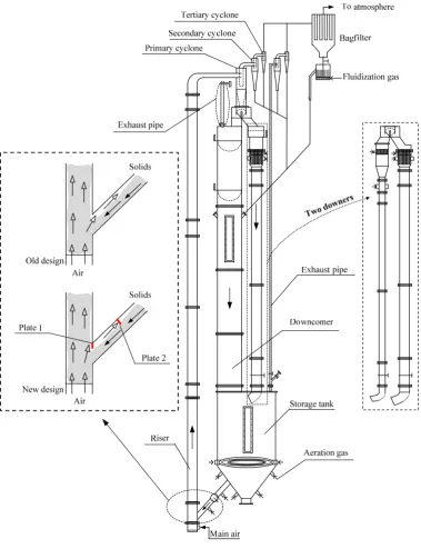
3.1 Experimental setup... 54
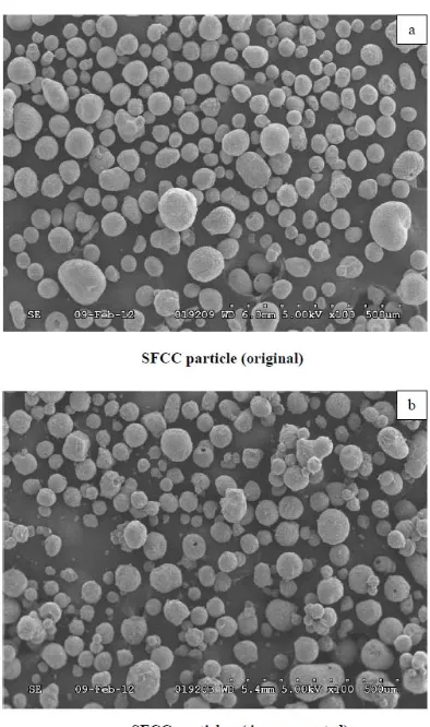
3.2 Preparation of particles ... 57
3.3 Measurements of Ug and Gs ... 60
3.3.1 Measurement of superficial gas velocity ... 60
3.3.2 Measurement of solids circulation rate ... 60
xi
3.6 Measurement of ozone concentration ... 67
3.6.1 Ozone generation ... 67
3.6.2 Ozone sampling ... 70
3.6.3 Ozone testing ... 71
3.6 Summary ... 73
Nomenclature ... 74
References ... 76
CHAPTER 4 Hydrodynamics in a HDCFB Riser-Solids Holdup and Flow Development ... 78
4.1 Introduction ... 78
4.2 Experimental details... 81
4.2.1 CFB experimental setup ... 81
4.2.2 Measurements of solids holdup ... 83
4.3 Results and discussion ... 87
4.3.1 Achieving high flux/density operating conditions in CFB riser ... 87
4.3.2 Axial profiles of solids holdup ... 90
4.3.3 Radial profiles of solids holdup ... 93
4.3.4 Flow development of solids holdup ... 96
4.3.5 Flow fluctuation in the high flux/density riser ... 101
xii
References ... 106
CHAPTER 5 Hydrodynamics in a HDCFB Riser-Particle Velocity and Solids Flux ... 109
5.1 Introduction ... 109
5.2 Experimental details... 111
5.2.1 CFB experimental setup ... 111
5.2.2 Measurements of solids holdup and particle velocity ... 114
5.3 Results and discussion ... 118
5.3.1 Axial profiles of cross-sectional average particle velocity ... 118
5.3.2 Radial profiles of particle velocity ... 120
5.3.3 Flow development profiles of solids flux ... 126
5.3.4 Relationship between solids holdup, particle velocity and solids flux ... 131
5.4 Conclusions ... 139
Nomenclature ... 140
References ... 141
CHAPTER 6 Hydrodynamics in a High Flux CFB Downer ... 144
6.1 Introduction ... 144
6.2 Experimental details... 145
6.2.1 CFB experimental setup ... 145
xiii
6.3.1 Radial profiles of solids flow ... 152
6.3.2 Development of solids flow ... 159
6.3.3 Axial profiles of solids flow ... 163
6.4 Conclusion ... 167
Nomenclature ... 168
References ... 170
CHAPTER 7 Catalytic Ozone Decomposition in a High Density CFB Riser ... 173
7.1 Introduction ... 173
7.2 Experimental details... 175
7.2.1 CFB experimental setup ... 175
7.2.2 Measurements of solids holdup ... 178
7.2.3 Catalyst preparation ... 179
7.2.4 Ozone generation and testing ... 180
7.3 Results and discussion ... 183
7.3.1 Axial and radial profiles of ozone concentration ... 183
7.3.2 Effect of operating conditions on ozone concentration ... 189
7.3.3 Relationship between ozone concentration and solids holdup ... 191
7.3.4 Performance of the CFB reactor ... 193
xiv
References ... 197
CHAPTER 8 Catalytic Ozone Decomposition in a High Flux Gas-solids CFB Downer ... 200
8.1 Introduction ... 200
8.2 Experimental details... 202
8.2.1 CFB experimental system ... 202
8.2.2 Measurements of solids holdup ... 204
8.2.3 Catalyst preparation ... 206
8.2.4 Ozone generation and testing ... 207
8.3 Results and discussion ... 210
8.3.1 Radial profiles of ozone concentration ... 210
8.3.2 Axial profiles of ozone concentration ... 211
8.3.3 Effect of operating conditions on ozone concentration ... 215
8.3.4 Relationship between solids holdup and ozone concentration ... 217
8.3.5 Reactor performance ... 219
8.4 Conclusions ... 221
Nomenclature ... 222
References ... 224
CHAPTER 9 Conclusions and Recommendations ... 228
xv
9.3 Recommendations ... 234
Appendix 1. Raw data of solids holdup, particle velocity, and solids flux in the CFB riser ... 236
Appendix 2. Raw data of solids holdup, particle velocity and solids flux in the CFB downer .. 256
Appendix 3. Raw data of ozone concentration in the CFB riser ... 265
Appendix 4. Raw data of ozone concentration in the CFB downer ... 271
xvi
Table 2.1 Studies of fluidized bed reaction by using ozone decomposition. (part 1) ... 33
Table 2.2 Studies of fluidized bed reaction by using ozone decomposition. (part 2) ... 34
Table 3.1 Locations of pressure taps ... 62
Table 3.2 Test results for ozone generator performance ... 68
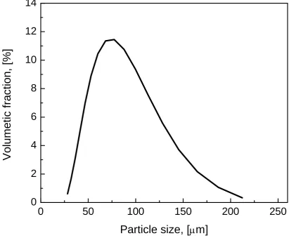
Table 4.1 Size distribution of the FCC particles. ... 83
Table 5.1 Size distribution of the FCC particles ... 113
Table 6.1 Size distribution of the FCC particles ... 147
Table 7.1 Size distribution of the FCC particles. ... 180
xvii
Figure 2.1 Typical schematic of circulating fluidized bed riser (Zhu, 2005) ... 12
Figure 2.2 Typical solids holdup profile (Zhu, 2005) ... 13
Figure 2.3 Typical axial profiles of solids holdup for FCC particles (Issangya et al., 1999) ... 14
Figure 2.4 Schematic profile of radial solids flow structure (Bai et al., 1995) ... 15
Figure 2.5 Radial solids holdup profile (Pärssinen and Zhu, 2001a) ... 16
Figure 2.6 Radial particle velocity profiles (Pärssinen and Zhu, 2001b) ... 17
Figure 2.7 Conceptual of circulating fluidized bed downer ... 21
Figure 2.8 Axial gas-solids flow structure in the downer (Zhu, 2005) ... 22
Figure 2.9 Axial distribution of pressure (Wang et al., 1992) ... 23
Figure 2.10 Radial profiles of particle velocity and gas velocity in the downer and riser (Zhu et .. al., 1999) ... 24
Figure 2.11 Radial distribution of solids holdup in the downer and the riser (Zhu et al., 1999) 25 Figure 2.12 Radial profiles along the riser and downer under different operating ... 27
Figure 2.13 Radial flow structures in CFB riser and downer (Bi and Zhu, 1993) ... 28
Figure 2.14 Effect of solids circulation rates and superficial gas velocity on the lengths of radial flow development for the riser and the downer. (Zhang et al., 2001) ... 29
Figure 2.15 Axial ozone concentration profile (Ouyang et al., 1993 and 1995) ... 35
Figure 2.16 Axial profile of solids holdup in the riser (Ouyang et al., 1995) ... 36
xviii
Figure 2.19 Ozone conversions in CFB downer (Fan et al., 2008) ... 39
Figure 2.20 Axial profiles of solids holdup in the riser and (Zhang et al., 1999) ... 40
Figure 2.21 Radial profiles of solids holdup in riser and downer (Zhang et al., 1999) ... 41
Figure 2.22 Contact efficiency as a function of Damköhler number ... 42
Figure 3.1 Schematic diagram of the multifunctional CFB system. ... 55
Figure 3.2 Particles activation process. ... 57
Figure 3.3 SEM images of original and impregnated SFCC particles at × 500 magnification. .. 58
Figure 3.4 Particles size distribution of FCC particles. ... 59
Figure 3.5 Schematic diagram of the novel optical fiber probe and its working principle. ... 63
Figure 3.6 Schematic diagram of the apparatus for solids concentration calibration of optical ... fiber probes. ... 64
Figure 3.7 Solids holdup calibration curve of the optical fiber probe for FCC catalyst particles 65 Figure 3.8 Stability of the inlet ozone concentration against time. ... 69
Figure 3.9 Ozone sampling and testing. ... 70
Figure 3.10 Schematic diagram of TEI 49i ozone analyzer. ... 72
Figure 4.1 Schematic diagram of the multifunctional CFB system. ... 81
Figure 4.2 Schematic diagram of the novel optical fiber probe and its working principle. ... 85
Figure 4.3 Characteristics of flow structure under extremely high flux/density in a CFB riser. . 87
xix
conditions. ... 93
Figure 4.6 Radial solids holdup distribution for various operating conditions. ... 95
Figure 4.7 Overall view of the solids hold up under different operating conditions. ... 97
Figure 4.8 Solids holdup distribution in different radial regions for various operating conditions ... 98
Figure 4.9 RNI’s of solids holdup the riser under different operating conditions ... 100
Figure 4.10 Radial profiles of local solids holdup, standard deviation and intermittency indices .. along the riser under different operating conditions. ... 102
Figure 5.1 Schematic diagram of the multifunctional CFB system. ... 111
Figure 5.2 Schematic diagram of the novel optical fiber probe and its working principle. ... 114
Figure 5.3 Axial profiles of average particle velocity and corresponding solids holdup ... 118
Figure 5.4 Radial profiles of particle velocity and corresponding solids holdup. ... 120
Figure 5.5 Radial particle velocity distribution for various operating conditions. ... 121
Figure 5.6 Development of radial profiles of local particle velocities. ... 122
Figure 5.7 RNI’s of particle velocity the riser under different operating conditions. ... 124
Figure 5.8 Variation of RNI (Vp) with (a) reduced centerline particle velocity and (b) reduced .... wall particle velocity in the riser at different operating conditions. ... 125
Figure 5.9 Radial profiles of local solids flux under different operating conditions. ... 126
Figure 5.10 Typical radial profile of solids flux under low and high flux/density ... 128
Figure 5.11 Radial profiles of (a) solids holdup, (b) particle velocity, and (c) solids flux. ... 131
xx
Figure 5.14 Relationship between cross-sectional average solids holdup and particle velocity 136
Figure 5.15 Relationship between cross-sectional average solids holdup and particle ... 137
Figure 6.1 Schematic diagram of the multifunctional CFB system. ... 145
Figure 6.2 Schematic diagram of the novel optical fiber probe and its working principle. ... 149
Figure 6.3 Radial profiles of solids holdup along the downer under different ... 152
Figure 6.4 Overview of solids holdup along the downer under different ... 153
Figure 6.5 Radial profiles of particle velocity along the downer under different ... 155
Figure 6.6 Overview of particle velocity along the downer under different ... 156
Figure 6.7 Radial profiles of solids flux along the downer under different ... 157
Figure 6.8 Overview of solids flux along the downer under different ... 158
Figure 6.9 Axial development of radial solids holdup along the downer under ... 159
Figure 6.10 Axial development of RNI(εs) along the downer under ... 161
Figure 6.11 Axial profiles of cross-sectional mean solids holdup along the downer ... 163
Figure 6.12 Axial profiles of cross-sectional mean particle velocity along the downer ... 165
Figure 7.1 Schematic diagram of the multifunctional CFB and ozone testing system. ... 175
Figure 7.2 Schematic diagram of the novel optical fiber probe and its working principle. ... 177
Figure 7.3 Axial distributions of the average dimensionless ozone concentration ... 183
Figure 7.4 Axial distributions of the dimensionless ozone concentration and the corresponding .. solids holdup at different radial positions. ... 185
xxi
conditions. ... 187
Figure 7.7 The effect of solids circulation rate on the local dimensionless ozone concentration. .. ... 189
Figure 7.8 The effect of superficial gas velocity on the local dimensionless ozone concentration. ... 190
Figure 7.9 Relationship between the conversion and solids holdup. ... 191
Figure 7.10 Effects of Damköhler number on overall ozone conversion. ... 193
Figure 8.1 Schematic diagram of the multifunctional CFB and ozone testing system. ... 202
Figure 8.2 Schematic diagram of the novel optical fiber probe and its working principle. ... 204
Figure 8.3 Radial profiles of dimensionless ozone concentration and the corresponding solids .... holdup. ... 210
Figure 8.4 Axial profiles of the average dimensionless ozone concentration and the ... corresponding solids holdup. ... 211
Figure 8.5 Axial profiles of dimensionless ozone concentration and the corresponding solids ... holdup at different radial positions. ... 213
Figure 8.6 Overall view of the dimensionless ozone concentration and the corresponding solids . holdup at different operating conditions. ... 214
Figure 8.7 Effects of superficial gas velocity on the dimensionless ozone concentration. ... 215
Figure 8.8 Effects of solids circulation rate on the dimensionless ozone concentration. ... 216
Figure 8.9 Relationship between overall ozone conversion and solids holdup. ... 217
1
CHAPTER 1
Introduction
Hydrodynamics and reactor performance of high solids flux/density gas-solids circulating fluidized bed riser and downer reactors are studied in this work. An introduction to the research background, objectives and thesis structure are presented in this chapter.
1.1 Background
Many chemical processes such as combustion, Fischer-Tropsch synthesis, partial oxidation, and fluid-catalytic cracking (FCC) have been utilizing gas-solids fluidized bed reactors (Bi and Fan, 1992 and Zhu and Cheng, 2005). The reactor performance is influenced both by the hydrodynamics and the chemical reaction itself. Fluidization occurs when a gas is forced to flow vertically through a bed of particles at such a rate that buoyancy of the particles is completely supported by the drag force imposed by the gas (Zhu and Cheng, 2005). With increasing gas velocity, the bed behaviors are changed. There are at least six different fluidization regimes: particulate fluidization, bubbling fluidization, turbulent fluidization, slugging fluidization, fast fluidization, and pneumatic transport (Zenz, 1949; Yerushalmi et al., 1976; Grace, 1986; Hirama, 1992 and Lim et al., 1995). The bubbling and turbulent fluidization are collectively considered as low-velocity or conventional fluidization.
When the superficial gas velocity is increased beyond a critical value (Bi et al., 1995), significant amount of particles will be entrained. The entrained solid particles must be replaced or the bed empties rapidly. A circulating fluidized bed (CFB) system is often used to maintain continuous operation, with gas-solids separation devices capturing the solids and returning them to the bottom of the reactor (often called riser) via a return system (standpipe or downcomer).
2
riser reactors provide many advantages over conventional bed reactors such as higher gas-solids contacting efficiency, reduced axial dispersion for both gas and solids and higher gas/solids throughput (Berruti et al., 1995 and Zhu et al., 1995). On the other hand, a CFB riser still suffers from severe solids backmixing, macro segregations of gas and solids due to the non-uniform flow structure in axial and radial directions, and micro segregations caused by particle clustering. Resulting from both gas and solids flowing against gravity (Zhu et al., 1995), these drawbacks reduce gas-solids contacting efficiency and lead to undesired distribution of products due to the reduced selectivity.
The disadvantages of the riser reactor caused by the hydrodynamic effects could be overcome in a new type of reactor, a CFB downer reactor (Zhu et al., 1995; Bai et al., 1995 and Wei and Zhu, 1996), where gas and solids flow co-currently downward, in the same direction with gravity.
In a CFB downer, particles accelerate much more quickly since they gain momentum from both the gas and gravity. Hydrodynamic studies show that the radial distribution of flow parameters such as solids holdup and particle velocity in CFB downers is more uniform than those in the CFB risers (Wei et al., 1994; Zhang, 1999 and Qi et al., 2008). This radial uniformity leads to nearly plug flow for both phases in the downer (Zhang, 1999 and Manyele et al., 2003). With reduced axial dispersion and more uniform gas and solids residence times, CFB downer reactors become more advantageous over CFB riser reactors for reactions requiring short residence times (Wei and Zhu, 1996), especially where intermediates are the desired products, for example, fluid catalytic cracking process of heavy oil (Zhu et al., 1995 and Zhang et al., 1999).
3
reactions where a high solids/gas ratio is required, since the reaction intensity is limited by the lower solids concentration. To overcome this weakness, Bi and Zhu (1993) proposed the concept of the high density circulating fluidized bed (HDCFB) riser. Subsequent studies on HDCFB have shown that solids holdups as high as 25% can be achieved in such a unit (Issangya et al., 1997-2000 and Pärssinen et al., 2001) with carefully controlled operation. However, few attempts have been made to achieve high flux/density in a cocurrent downflow system. Therefore, there is an urgent need to study the characteristics of the downer operating at high density/flux for understanding the flow mechanics and increasing its industrial applications.
Previous research works and practical applications have demonstrated that the CFB reactors could work with high efficiency under a very wide range of operating conditions, and hydrodynamics behavior which can significantly affect the performance of the reactors, e.g. mass and heat transfer, extent of reaction, gas and solids residence time distribution and mixing. So understanding the hydrodynamics is of prime importance for design and scale-up of efficient commercial fluidization processes. On the other hand, a study of a chemical reaction in a fluidized bed can supply more direct information on reactor performance. Grace and Bi (1997) pointed out that to better understand mass and heat transfer characteristics in reactors, to optimize the reactor design, and to develop and verify reactor models, hot-model (with reactions) studies providing axial and radial reactant concentration profiles are necessary.
Among previous hot-model studies, ozone decomposition reaction, catalyzed by Fe2O3 has
become a surrogate reaction for the characterization of gas-solids contact in CFB reactors (Kagawa et al., 1990; Jiang et al., 1990 and 1991; Bi et al., 1992; Pagliolico et al., 1992; Ouyang
4
1.2 Research objectives
To comprehensively study hydrodynamics at high density/flux conditions in circulating fluidized beds and to map profiles of radial and axial reactant concentrations for reactor design and model development, based on literature review of previous studies on both hydrodynamics and ozone decomposition in CFB reactors, the objectives of this study are:
To modify the experimental unit to further increase the solids circulation rate, enabling high density/flux operations in the riser and downer,
To obtain the axial/radial solids holdup and particle velocity profiles in the riser under a wide range of operating conditions especially at high density/flux conditions,
To obtain the axial/radial solids holdup and particle velocity profiles in the downer under a wide range of operating conditions especially at high density/flux conditions,
To obtain the axial/radial profiles of ozone concentration in the riser under a wide range of operating conditions especially at high density/flux conditions,
To obtain the axial/radial profiles of ozone concentration in the downer under a wide range of operating conditions especially at high density/flux conditions.
1.3 Thesis structure
This thesis follows the “Integrated-Article Format” as outlined in the UWO Thesis Regulation. Chapter 1 gives a general introduction followed by a detailed literature review in Chapter 2. Chapter 3 provides detailed descriptions on experimental setup, measurement techniques, and experimental procedures.
5
Chapter 5 describes the experimental results on particle velocity in the high density CFB riser. Radial and axial profiles of solids holdup under various operating conditions are presented. A comparison between the flow structures in low density and high density CFB risers is discussed. Correlation between particle velocity and solids flux against solids holdup is also studied at low and high solids flux/density conditions.
Chapter 6 describes the hydrodynamics in the downer reactor under high solids flux up to 300 kg/m2s. A comprehensive study of solids holdup, particle velocity and solids flux is presented.
Chapter 7 describes the experimental results from catalytic ozone decomposition in the high density/flux CFB riser. Radial and axial profiles of ozone concentration at various operating conditions are presented. Reactor performance is also discussed.
Chapter 8 describes the experimental results from catalytic ozone decomposition in the high density/flux CFB downer. Radial and axial profiles of ozone concentration at various operating conditions are presented. Reactor performance is also discussed.
6
References
Bai D., Shibuya E., Masuda Y., Nishio K., Nakagawa N. and Kato K., (1995), Distinction between upward and downward flows in circulating fluidized beds, Powder Technology 84(1), 75-81
Berruti F., Pugsley TS., Godfroy, L., Chaouki, J. and Patience, GS., (1995), Hydrodynamics of circulating fluidized bed risers, A review, The Canadian Journal of Chemical Engineering 73(5), 579-602
Bi HT. and Fan LS., (1991), Regime transition in gas-solid circulating fuidized beds, Paper#101e presented at the AIChE Annual Meeting, Los Angele, Nov, 17-22
Bi HT. and Zhu JX., (1993), Static instability analysis of circulating fluidized beds and concept of high-density risers, AIChE Journal 39, 1272-1280
Bolland O. and Nicolai R., (2001), Describing mass transfer in circulating fluidized beds by ozone decomposition, Chemical Engineering Communications 187(1), 1-21
Fan C., Bi, X., Lin W. and Song W., (2008a), Mass transfer and reaction performance of the downer and its hydrodynamic explanation, The Canadian Journal of Chemical Engineering 86(3), 436-447
Fan C., Zhang Y., Bi X., Song W., Lin W. and Luo L., (2008b), Evaluation of downer reactor performance by catalytic ozone decomposition, Chemical Engineering Journal 140(1-3), 539-554
Grace JR., (1986), Contacting modes and behaviour classification of gas-solid and other two-phase suspension, The Canadian Journal of Chemical Engineering 64, 353-363
Grace JR., (1990), High-velocity fluidized bed reactors, Chemical Engineering Science 45(8), 1953-1966
Grace JR. and Bi H., (1997), Introduction to circulating fluidized beds, in Circulating Fluidized Beds (editor(s), Grace JR., Avidan AA. & Knowlton TM.), Engineering Foundation, New York, 1-19
Herbert PM., Gauthier, TA., Briens, CL. and Bergougnou MA., (1998), Flow study of a 0.05 m diameter downflow circulating fluidized bed. Powder Technology 96, 255-261
Hirama T., Takeuchi T., Chiba T., (1992), Regime classification of macroscopic gas-solid flow in a circulating fluidized-bed riser, Powder Technology 70, 215-222
Issangya AS., Bai D., Grace JR., Lim KS., and Zhu J., (1997), Flow behaviour in the riser of high-density circulating fluidized bed, AIChE Symposium Series 93, 25-30
7
Issangya AS., Bai D., Bi HT., Lim KS., Zhu J., and Grace JR., (1999), Suspension densities in a high-density circulating fluidized bed riser, Chemical Engineering Science 54, 5451-5460
Issangya AS., Grace JR., Bai DR., Zhu JX., (2000), Further measurements of flow dynamics in a high-density circulating fluidized bed riser, Powder Technology 111, 104-113
Jiang P., Bi HT., Jean RH. and Fan LS., (1991), Baffle effects on performance of catalytic circulating fluidized bed reactor, AIChE Journal 37(9), 1392-1400
Jiang P., Inokuchi K., Jean RH., Bi H. and Fan LS., (1990), Ozone decomposition in a catalytic circulating fluidized bed reactor, in Circulating Fluidized Bed Technology III (editor(s), Basu P., Horio M. and Hasatani M.), Pergamon Press, Oxford, 557-562
Jin Y., Zhu JX. and Yu Z. (1997), Novel configuration and varants, Chapter 16 in Circulating fluidized beds (Eds. Grace JR., Avidan AA. and Knowlton TM.) pp. 525-567, Blackie Aacademic and Professional, London
Kagawa H., Mineo H., Yamazaki R. and Yoshida K., (1990), A gas-solid contacting model for fast fluidized bed, in Circulating Fluidized Bed Technology III (editor(s), Basu P., Horio M. and Hasatani M.), Pergamon Press, Oxford, 551-556
Li DB., Zhu J., Ray MB. and Ray AK., (2011), Catalytic reaction in a circulating fluidized bed downer, Ozone decomposition, Chemical Engineering Science 66 (20), 4615-4623
Li DB., Ray AK., Ray MB. and Zhu J., (2013), Catalytic reaction in a circulating fluidized bed riser, Ozone decomposition, Powder Technology 342(15), 65-73
Lim KS., Zhu JX., and Grace JR., (1995), Hydrodynamics of gas fluidization, Int. J. Multiphase Flow, 21(Suppl.), 141-193
Manyele SV., Zhu J. and Zhang H., (2003), Analysis of the microscopic flow structure of a CFB downer reactor using solids concentration signals, International Journal of Chemical Reactor Engineering 1, A55
Ouyang S., Li XG. and Potter OE., (1995), Circulating fluidized bed as a catalytic reactor, experimental study, AIChE Journal 41(6), 1534-1542
Ouyang S., Lin J. and Potter OE., (1993), Ozone decomposition in a 0.254 m diameter circulating fluidized bed reactor, Powder Technology 74(1), 73-78
Pärssinen JH. and Zhu JX., (2001a), Axial and radial solids distribution in a long and high-flux CFB riser, AIChE Journal 47, 2197-2205
Pärssinen JH. and Zhu JX., (2001b), Particle velocity and flow development in a long and high-flux circulating fluidized bed riser, Chemical Engineering Science 56, 5295-5303
8
Qi XB., Zhang H. and Zhu J., (2008), Friction between gas-solid flow and circulating fluidized bed downer wall, Chemical Engineering Journal 142(3), 318-326
Schoenfelder H., Kruse M., and Werther J., (1996), Two-dimensional model for circulating fluidized-bed reactors, AIChE Journal 42(7), 1875-1888
Squires AM., (1986), The story of fluid catalytic cracking, the first circulating fluid bed, in Circulating Fluidized Bed Technology (editor(s), Basu, P.), Pergamon Press, Toronto, 1-19
Syamlal M. and O'Brien TJ., (2003), Fluid dynamic simulation of O3 decomposition in a
bubbling fluidized bed, AIChE Journal 49(11), 2793-2801
Wei F. and Zhu JX., (1996), Effect of flow direction on axial solids dispersion in gas-solids cocurrent upflow and downflow systems, The Chemical Engineering Journal and the Biochemical Engineering Journal 64(3), 345-352
Wirth KE. and Schiewe T. (1998), Flow structure in a dowenr reactor, in Fluidization IX (Eds. Fan LS. and Knowlton TM), pp 253-260, Eng. Foundation, New York
Yerushalmi J., Turner DH. and Squires AM., (1976), The fast fluidized bed, Ind. Eng. Chem., Proc. Des. Dev. 15, 47-57
Zhang H., Zhu JX. and Bergougnou MA., (1999), Flow development in a gas-solids downer fluidized bed, The Canadian Journal of Chemical Engineering 77(2), 194-198
Zenz FA., (1949), Two-phase fluidized-solid flow, Ind. Eng Chem. 41, 2801-2806
Zhu JX., Yu ZQ., Jin Y., Grace JR. and Issangya A., (1995), Cocurrent downflow circulating fluidized bed (downer) reactors-A state of the art review, The Canadian Journal of Chemical Engineering 73(5), 662-677
9
CHAPTER 2
Literature Review
2.1 Introduction
Particulate technology has played an important role in many industrial processes such as chemical processing, mineral processing, pharmaceutical production and energy-related process, etc and in particular, gas-solids fluidization has been extensively employed in recent decades (Grace, 1990 and Zhu and Cheng 2005). Particles contained in a column can be fluidized when gas is introduced via a gas distributor at the bottom of the column. Different hydrodynamic regime can be observed depending on the particle characteristics and the magnitude of the superficial gas velocity. With increasing gas velocity, these flow regimes are fixed bed, bubbling fluidization, slugging fluidization, turbulent fluidization, fast fluidization and pneumatic conveying regimes. The bubbling, slugging and turbulent fluidization regimes are considered as conventional fluidization. The main characteristic of the conventional fluidized beds is that the beds operate at relatively low superficial gas velocity (usually less than 1-2 m/s) with little solids entrainment.
When the superficial gas velocity is increased beyond a critical superficial gas velocity Usc,
10
CFB risers allow a continuous operation and offer advantages with respect to mass and heat transfers. The overall efficiency of a riser is improved when a uniform distribution of the solid particles is obtained. At high solids fluxes (Gs > 200 kg/m2s, operating conditions at which most
of the FCC units are operated), radial uniformity is disturbed by lateral segregation and backmixing phenomena resulting in core-annulus flow structure. Moreover, axial segregation phenomenon results in a distinctive dilute zone in the upper part and a dense zone in the bottom part of the riser (Zhu and Cheng, 2005 and van engelandt et al., 2007).
The disadvantages of the riser reactor caused by the hydrodynamic effects of both gas and solids flowing against gravity can be overcome in a new type of chemical reactor - downer reactor. As both phases flow downwards in the same direction as gravity, axial solids dispersion and the non-uniformity of radial gas and solid flow are reduced (Bai et al., 1995; Bolkan et al., 2003 and Luo et al., 2007).
Compared to a riser reactor, a downer reactor has many advantages such as much more uniform gas-solids flow with less aggregation, less gas and solids backing mixing, and shorter residence time (Wei et al., 1994; Zhang et al., 1999; and Qi et al., 2008). These characteristics are usually beneficial to the processes that require a short and uniform residence time distribution for gas and solid phases to decrease byproducts and overreacting. Downer reactors have therefore attracted many investigations in the past decade (Zhu et al., 1995).
11
(Bolland, 1998; Schoenfelder et al., 1996; Ouyang et al., 1995; Kagawa et al., 1990; Pagliolico
et al., 1992 and Jiang et al., 1991) are some examples of reactions in circulating fluidized bed reactors. Ozone decomposition reaction is the most widely-adopted model reaction because it takes place at ambient temperature and is of first-order kinetic reaction.
An introduction to the hydrodynamic characteristics of the CFB reactors including riser and downer and the experimental research with regard to ozone decomposition in CFB reactors are presented in the next section.
2.2 Hydrodynamics in CFB riser
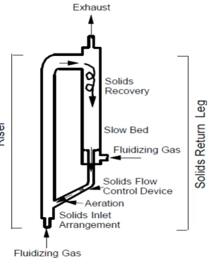
Circulating fluidized bed (CFB) riser reactors have been used for a wide range of industrial applications over the past 50 years (Grace, 1990 and Zhu and Cheng, 2005). In a CFB riser system as shown in Figure 2.1, solids must be continuously fed into the bed bottom and entrained out of the reactor by high velocity gas flow to maintain the required solids holdup. Solids captured at the top are sent back to the bottom of the riser via the recirculation system. Fast fluidization is achieved and most reactions take place in the riser reactors (Zhu and Cheng, 2005).
12
Figure 2.1 Typical schematic of circulating fluidized bed riser (Zhu, 2005)
Hydrodynamics are normally characterized by studies of solids holdup and gas and solids velocity. Knowledge of gas and solids distribution and flow behavior in CFB reactors is the key to successful design and operation of any CFB riser system as mass transfer, heat transfer, gas and solids interaction are often influenced by hydrodynamics (Grace, 1990).
2.2.1 Axial profiles of solids concentration
13
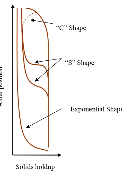
Figure 2.2 Typical solids holdup profile (Zhu, 2005)
In the exponential axial profile, the particles are being introduced into the riser and accelerated upwards by the fluidization gas very quickly to a certain point above the distributor, where the particle velocity becomes constant or to be more precise, the acceleration becomes negligible. A C-shape may be observed in a similar system with an abrupt exit. The S-shape profile is believed to be related to the high solids flux operation. Typical axial profiles in a CFB riser are shown in Figure 2.3.
Axial posi
tion
Solids holdup
“C” Shape
“S” Shape
14
0.0 0.1 0.2 0.3 0.4 0.5
0 1 2 3 4 5 6
Height,
[m]
Apparent solids holdup, [-] Gs kg/m2s
18 44 68 138 200 240
Figure 2.3 Typical axial profiles of solids holdup for FCC particles (Issangya et al., 1999)
The axial voidage or holdup profile can be affected by many operating variables such as solids circulation rate, superficial gas velocity, bed diameter, particle properties, like density and size distribution, total solids inventory, solids inlet configuration, riser exit structure, secondary air injection and the solids reintroduction level into the riser. With a higher solids flux, a more dense bed can be observed and the transition region between the dense bed and dilute phase occurs higher up in the riser. The lower the solids flux, the less solids holdup exists in the riser. The superficial gas velocity also affects the solids holdup. With an increase in Ug, the solids holdup
decreases, or inversely, the axial voidage increases. Increasing the bed diameter would result in a higher voidage and more uniformity. The coexistence of a bottom dense region and an upper dilute region characterizes the solids flow in a riser where the solids holdup in the dense phase zone ranges from 0.1 to 0.3, while the holdup profiles in the dilute region can be approximately 0.01 to 0.09 (Li and Kwauk, 1980, Schnitzlein and Weinstein, 1988, Pärssinen and Zhu, 2001).
15
arguments based on the length of the second acceleration region make the particle velocity profile be controversial (Bai et al., 1990). The experimental results that this second acceleration period is not very short but rather may extend well into the riser, while some particles may in fact still be accelerating at the top of the riser when they are forced to exit. Some experiments have shown that solids in fast fluidized beds are still in acceleration along most of the bed height, especially at low gas flow rate and high solids circulation rate (Bai et al., 1990).
However, it has become widely accepted to assume the acceleration period to be very short (Bai
et al., 1990). This acceleration region in effect becomes the guideline to determine the transition between dense and dilute phases, since in the dense phase particle velocity is very low compared to the velocity in the dilute region. Bai et al. (1990) indicated that this acceleration zone may occupy from 1/3 to 2/3 of the riser height.
2.2.2 Radial profiles of solids concentration and particle velocity
A core-annular type radial solids flow with a dense particle layer in the wall region and a dilute core region is known to exist in the riser as shown in Figure 2.4.
16
This can be described as a low density, high velocity gas-solids core region surrounded by slower moving or even downward flowing high solids concentration annular region (Bai et al., 1995). Grace et al. (1997) suggested that particle exchanges occur between the dilute core and the dense wall region, as temporal and spatial accumulations of particles in the wall region form a transient dense particle layer or streamers. Non-uniform particle distributions or the presence of localized dense zones usually results from the existence of particle clusters and greatly influences the hydrodynamic characteristics of the system (Grace et al., 1997).
Typical radial voidage profiles reported by Pärssinen and Zhu (2001b) are shown in Figure 2.5. A dilute central region and a denser wall region bed structures are observed. Solids holdup is seen to be low and relatively uniform in the central region up to about 70%-85% of the column radius, after which the solids concentration increases dramatically towards the wall, especially for the high solids flux conditions.
0.0 0.2 0.4 0.6 0.8 1.0
0.0 0.1 0.2 0.3 0.4 0.5 0.6
S
o
lids holdup
[-]
Dimensionless coordinate [-]
G
s=100 kg/m
2s G
s=400 kg/m
2s U
g=8.0 m/s
z=3.96 m
z=3.96 m
z=6.34 m
z=6.34 m
z=8.74 m
z=8.74 m
Issangya
et al
.(2000b)
G
s=391 kg/m
2s U
g=7.5 m/s
z=3.40 m
17
Corresponding to the solids holdup profile, Pärssinen and Zhu (2001b) presented the particle velocity profile as seen in Figure 2.6. Particle velocities were directed upwards in the core of the column, with a magnitude similar to the superficial gas velocity at the column axis. The average velocity then fell as the radial position moves toward the wall, becoming negative in a layer adjacent to the wall. Ascending particles were dominant in the center of the column, whereas there were more descending than ascending particles near the wall. The magnitudes of the velocities of rising particles at the axis of the column were similar to the superficial gas velocity, while the magnitudes of downward velocities are significantly lower.
0.0 0.2 0.4 0.6 0.8 1.0
-2 0 2 4 6 8 10 12 14 16
Particle velocity [m/s]
Dimensionless coordinates [-]
Gs [kg/m2s] 100 3002.73 m 3.96 m 6.34 m 8.74 m
18
2.3 Effects on the flow structure
2.3.1 Entrance and exit effect
As mentioned earlier, the CFB riser, hydrodynamically, had featured by a high concentration of solids flowing near the wall with most of the gas passing through the core dilute region (Bai et al., 1995). A uniform distribution of solids along the riser was of importance in the successful design of riser reactors (Yan et al., 2008). Good understanding of the solids flow structure in riser reactors was critical for proper industrial design. It had been found that operating conditions (Bai et al., 1992), inlet and outlet structures (Jin, 1988), and riser diameters (Yan and Zhu, 2004) impact the axial and radial solids distributions.
A large number of studies had examined the influence of entrance and exit geometry in CFB risers. Recent experimental results (Jin, 1988, Brereton and Grace, 1994, Gwyn, 1993, and Cheng et al., 1998) demonstrated that the geometry of the riser exit could greatly influence the performance of CFBs, by affecting pressure and solids holdup profiles, not only close to the roof, but also at a considerable distance down the column. There were two types of exit configurations categorized as abrupt exit and smooth exit. With an abrupt exit, a relatively high solids concentration and a low particle velocity were observed, while with a smooth exit, the restriction to the solids flow was much less, and the dense suspension zone disappears. Reviews by Lim et al. (1995) concluded that the exit design could affect the density profile over several meters in the upper region of a riser. Bai et al. (1992) compared the influence exerted by different exit and inlet structures of fast fluidized beds on the axial voidage distribution. They reported that with a restrictive exit design, the voidage profile had a C-shape, while the profile was S-shape when a very weakly restrictive entrance structure was employed.
2.3.2 Scale-up effect
19
diameter on gas dispersion coefficient was probably more than linear for small-diameter tubes, approximately linear for medium-size columns, and less than linear for large risers. Their observations appeared to agree with the above cited results (Yerushalmi and Avidan, 1985) of change in the turbulent intensity as a function of dp/ le (le is length of turbulent eddies), under the
assumption of le / D constant (Gore and Crowe, 1989). Yan and Zhu (2004) also studied the
scale-up effect of riser reactors on the distributions of solids concentration, particle velocity and solids flux in a twin-riser CFB system with 0.076 and 0.203 m inner diameters. They concluded that the solids concentration increased with increasing riser diameter and the radial profiles of the solids concentration were steeper with larger-diameter risers. It had also been found that the cross-sectional average particle velocity was somewhat lower for the larger riser with a steeper radial particle velocity profile. For the radial profile of the solids flux, a parabolic shape and a flat core shape profiles were found for the two risers respectively (Yan and Zhu, 2004, 2005 and Yan et al., 2005).
2.3.3 Riser geometry effect
20
transparent faces, separated by a distance which was usually in the range 10 to 25 mm (Grace and Baeyens, 1986).
Rectangular two-dimensional and the conventional three-dimensional beds differed qualitatively and quantitatively. The differences arose from bubble properties, such as bubble velocities, bubble coalescence properties, bubble shapes and wake characteristics, and solids ejection into the freeboard in bubbling or turbulent beds (Fan, 1990; Gera and Gautam, 1995; Almendros-Ibanez et al., 2006; Zhou et al., 2007 and Xu 2010). However, very few studies had been done in two-dimensional fluidized bed under fast fluidization conditions, in which the gas velocities are higher than 3 m/s (Xu 2010).
To clarify the effects of riser geometry on the flow behaviors, Xu (2010) compared the results of the solids distribution in both the rectangular riser and the cylindrical riser under a wide range of conditions. In their study, both axial and lateral profiles of solids holdup showed that the operating conditions played important roles in influencing the flow structure, and controlled the flow properties in the rectangular riser in the same way as that in cylindrical risers: increasing Ug
and reducing Gs resulted in a lower solids holdup. The solids concentration profile, within the
range of their study, remained low at the riser centre throughout the whole riser compared with the solids holdup in the wall region. Comparing the rectangular riser with the other cylindrical columns, it was found that the general shapes of the axial and lateral profile of solids holdup in rectangular riser were quite similar to that in cylindrical risers, but more uniform (Xu and Zhu, 2010; Xu et al., 2010 and Xu, 2010).
2.4 Hydrodynamics in CFB downer
21
upflow riser reactors as stated by many of the researchers (Bai, et al., 1991; Wang et al., 1992; Herbert et al., 1994; Zhu et al., 1995 and Herbert et al., 1998)
Figure 2.7 Conceptual of circulating fluidized bed downer
22
2.4.1 Three-section axial flow structure
In a downer reactor, gas and particles were fed from the top of the downer through separate gas and particle distributors. Upon entering the downer, gas immediately attained superficial velocity while particle velocity was initially close to zero (Zhang, 1999).
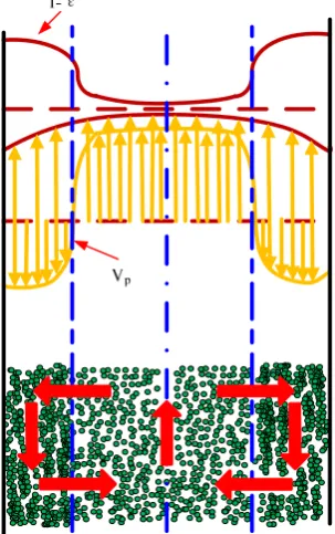
Figure 2.8 Axial gas-solids flow structure in the downer (Zhu, 2005)
23
particle velocity was equal to the gas velocity had been referred to as the first acceleration section (Zhang, 1999).
After acquiring the same velocity as the gas phase, solids were further accelerated by gravity while encountering drag in the upward direction exerted by the now slower moving gas phase. Therefore, particle velocity increased further until the slip velocity between the gas and particles reached a value where the drag force counter-balanced the gravitational force. This section had been referred to as the second acceleration section. In this section, particle velocity continued to increase but at a lower rate than in the first acceleration zone and pressure increased gradually.
Figure 2.9 Axial distribution of pressure (Wang et al., 1992)
When the drag was sufficient to balance the gravitational force, particles were not further accelerated and the remainder of the downer had been named the constant velocity section
1250 1500 1750 2000 2250
Pressure, P (Pa)
0.0
1.0
2.0
3.0
4.0
5.0
6.0
Axial position, h (m)
67
96
Gs
kg/m2
24
(Wang et al., 1992). In this section, particles traveled faster than gas and both particle and gas velocities remained constant. Pressure increased linearly along the downer and the pressure gradient was equal to the cross-sectional bed density, if wall friction was neglected.
This three-section axial flow structure had been confirmed by pressure and pressure drop measurements and the axial distribution of average particle velocity measured in a 140 mm downer (Wang et al., 1992). This flow structure was also consistent with the prediction by Kwauk (1964) in his generalized fluidization model.
2.4.2 Radial gas and solids flow structure
Measurements for radial profiles of gas and particle velocities and solids concentration in both downers and risers had been made in the 140 mm diameter riser-downer system (Wang, et al., 1992; Cao, et al., 1994 and Zhu et al., 1999). Typical radial profiles of gas and particle velocities measured in downer and the radial profile of solids concentration measured in both downers and risers were given in Figures 2.10 and 2.11 (Zhu et al., 1999).
Figure 2.10 Radial profiles of particle velocity and gas velocity in the downer and riser (Zhu et al., 1999)
0.0 0.2 0.4 0.6 0.8 1.0 Radial position, r/R 0.0 1.0 2.0 3.0 4.0 5.0 6.0 Gas velocit y, V g (m/s )
Ug Gs
m/s kg/m2s
4.1 15.9 Downer
4.3 12.1 Riser
0.0 0.2 0.4 0.6 0.8 1.0
Radial position, r/R
-2.0 0.0 2.0 4.0 6.0 8.0
Partic
le
v
e
locity, V
p
(m/s
)
Downer
Riser
Ug= 4.3 m/s
Gs= 31 kg/m
25
Compared with the radial flow structure in the riser, the radial distributions of gas and particle velocities and solids concentration were all significantly more uniform in the downer. For the radial distribution of solids concentration in the downer, a similar phenomenon as that in the riser was found; the local bed voidage was a function of the radial position r/R only, with a given average voidage at any axial position, independent of the superficial gas velocity and the solids circulation rate (Wang et al., 1992).
Figure 2.11 Radial distribution of solids holdup in the downer and the riser (Zhu et al., 1999)
Examining the radial profiles of the gas and particle velocities and the solids concentration in the downer in Figures 2.10 and 2.11, it was found that in the downer, local particle velocity could be higher than local gas velocity and a higher local solids concentration always corresponded to higher gas and particle velocities. This was contrary to the situation in the riser, where local particle velocity was always lower than local gas velocity and a higher local solids concentration always corresponded to lower gas and particle velocities (Zhu et al., 1999).
0.0
0.2
0.4
0.6
0.8
1.0
Radial position, r/R
0.00
0.01
0.02
0.03
0.04
0.05
0.06
Sol
ids f
racti
on,
Downer
Riser Ug= 2.9 m/s
Gs= 108 kg/m2s
27
Figure 2.12 Radial profiles along the riser and downer under different operating
28
The radial distributions of time-averaged solids holdups in Figure 2.12 showed distinct differences between the riser and the downer. In the riser, the overall radial structure generally showed a non-uniform solids holdup distribution with a dilute core and a dense annulus, with the radial profile being relatively flat in the core and solids holdup increasing sharply toward the wall in the annulus with the highest solids holdup right at the wall. The radial distribution of solids holdup was affected by the operating condition. However, the shapes of the two profiles were very similar, both increasing gradually with increasing r/R, reaching a maximum value near the wall at about r/R = 0.95 and then decreasing towards the wall, although the gas and particle velocity profiles were quite different for the downer and the riser.
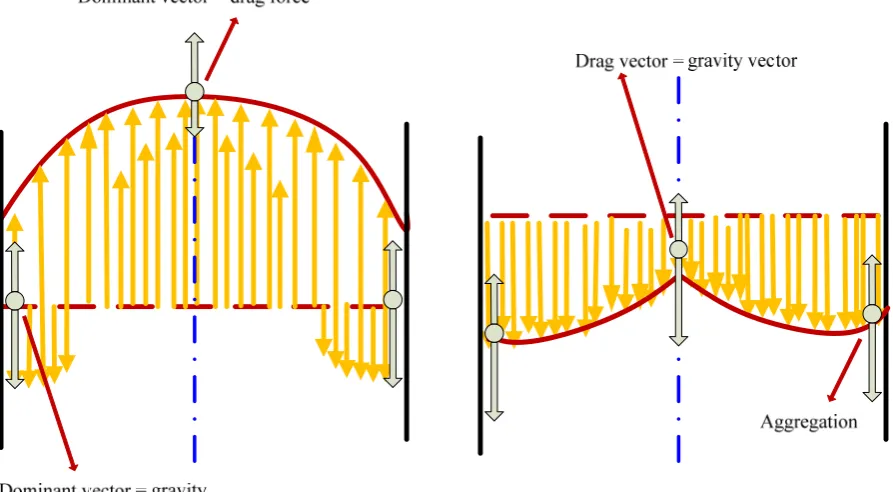
Compared to riser reactors, downer reactors had a much more uniform radial gas-solids flow pattern. This was likely due to the change of the direction of gas and solids flow from opposing gravity to following it. The following mechanism was provided to explain the more favorable radial flow structure in the downer (Bi and Zhu 1993).
29
As was shown in Figure 2.13, in both the downer and the riser, higher local solids concentration resulted in the reduction of drag coefficient (Zhang et al., 2001). In the riser (where the drag was the driving force for particle flow) reduction of drag decreases the upwards particle velocity, which in turn increased the tendency for particle aggregation (Bi and Zhu 1993). Increased particle aggregation then further reduced the drag and the local particle velocity, leading to steeper radial profiles for both gas and particle velocity. However, in the downer (flow in the direction of gravity so that gravity was the driving force), a reduction of the upwards drag force would result in increased downwards particle velocity, which in turn leaded to increased gas velocity. On the other hand, increased local gas and particle velocities in the downer tended to reduce the extent of particle aggregation, thus increasing the gas drag. Therefore, the system stabilizes by itself and a more uniform radial flow structure was present in the downer.
3. 5 3. 7 5. 5 5. 7 7. 2 8. 1 8. 2 10. 2 0 2 4 6 8 10 12 12 ~50 ~10 0 ~20 0
Ug G
s
LOD
(a) Wall region
3.5 3.7 5.5 5.7
7. 2 8. 1 8.2 10 .2 0 2 4 6 8 10 12 12 ~50 ~10 0~20 0 Ug Gs LO D
(b) Core region
Figure 2.14 Effect of solids circulation rates and superficial gas velocity on the lengths of radial flow
30
The length of the flow development (LOD) was the length that is needed for both the radial solids holdup profile and radial particle velocity to become fully developed (Zhang et al., 2001). In a downer, the length of flow of development was comparable to that of a riser. In the core region of downer, the length of flow of development was longer than in the core of a riser. However, the total length of flow of development was approximately equal. Length of development in both reactors increased with increasing solids holdup and decreasing gas velocity as shown in Figure 2.14. In a downer the radial distribution of solids hold up and particle velocity was uniform than in a riser, therefore, it became a less important parameter in design compared to a riser. This LOD can be increased by increasing the solids circulation and holdup and also by decreasing the gas velocity. For catalytic or non-catalytic reactions, smaller LOD was favorable since the axial solids dispersion was less uniform in the development zone. This resulted in unfavorable flow patterns and non-uniform residence times. In the long run it may lead to over-conversion of the particle reactions and formation of undesired products in reactors with longer LOD. Therefore, downer was preferred due to smaller length of development (Zhang
et al., 2001).
31
as the solids distribution in the downer was more uniform. In the riser, the radial heat transfer coefficient was non-uniform due to the solids holdup and formation of clusters especially at the wall.
2.5 Ozone decomposition in CFB reactors
2.5.1 Experimental researches with ozone decomposition
In order to improve the design and operation of commercial fluidized beds, studies have been conducted in conventional fluidized bed systems for both bubbling and turbulent fluidized bed conditions, where the decomposition of ozone has been used as a model reaction. Chemical reaction gives the direct information on reactor performance in contrast to any other method (Frye et al., 1958 and Jiang et al., 1991). Reactor performance investigations have also been carried out in CFB systems using ozone decomposition as the model reaction. Recently, high density circulating fluidized beds have become a hot research topic, especially on hydrodynamics. However, there are only a few published research studies dealing with catalytic reactions and these were in small-scale circulating fluidized bed reactors (Jiang et al., 1991 and Pagliolico et al., 1992).
32
33
Table 2.1 Studies of fluidized bed reaction by using ozone decomposition. (part 1)
Reactor material
Reactor diameter
(mm)
Reactor height
(m)
Ug
(m/s) Reactor
Gs
(kg/m2s)
Temperature
( ̊C ) Type of FCC
Particle size (µm)
Particle density (kg/m3)
Reaction rate (1/s)
Li et al., (2013) Aluminum 76 10 2-5 riser 50-150 20 FCC+ ferric
nitrate 67 1370 4.0
Li et al., (2011) Aluminum 76 5 2-5 downer 50-150 20 FCC+ ferric
nitrate 67 1370 4.0
Fan et al.,
(2008) Plexiglas 90 8.5 2.2-3.7 downer 8.4-28.8 -
FCC 62 1747 0.098 FCC+ferric
nitrate 72 1400 ml (g cat) -1 s-1
Bolland et al.,
(2001) Steel 411 8.5 5.6-7.2 riser 31-53 60 angular cast steel 117 3320 26-62
Schoenfelder
et al., (1996) - 400 15.6 2.4-4.5 riser 9-45 20
aluminum hydro silicate +10% silica + Iron Oxide
50 1420 0.001-0.003 M3/(s.kg)
Ouyang et al.,
(1995, 1996) Steel 254 10.85 2.0-7.5 riser 10-206 20
FCC+
34
Table 2.2 Studies of fluidized bed reaction by using ozone decomposition. (part 2)
Reactor material
Reactor diameter
(mm)
Reactor height
(m)
Ug (m/s) Reactor
Gs
(kg/m2s)
Temperature
( ̊C ) Type of FCC
Particle size (µm)
Particle density (kg/m3)
Reaction rate (1/s)
Pagliolico
(1992) - 50 4.5 3.8-8.8 riser 20.4-102 15
γ-alumina+
ferric oxide 82 2970 44.71
Jiang et al.,
(1991) Plexiglas 102 6.32 1.5-2.5
riser+
baffle ring 5.1-28.9 23
FCC+ferric
nitrate 89 1500 2.81-5.1
Sun et al.,
(1990) Aluminum 100 2.6 0.06-1.8
bubbling, slugging, turbulent
- - FCC+ferric nitrate
Wide, 60; Bimodel, 60;
Narrow, 60
- 1-9
Fryer et al., (1958, 1976)
Stainless
steel +glass 229 2
0.024-0.017 bubbling - 20
sand+iron
35
2.5.2 Ozone decomposition in the CFB riser reactor
0 2 4 6 8 10
0.0 0.2 0.4 0.6 0.8 1.0 D ime nsio nl ess con c en tra tion [-] Height [m]
r/R = 0.0 r/R = 0.3 r/R = 0.5 r/R = 0.7 r/R = 0.9 r/R = 1.0
U = 3.9 m/s G
s = 34 kg/m
2s
kr = 14.18 s-1
0 2 4 6 8 10
0.0 0.1 0.2 0.3 0.4 0.5 0.6 Dim ensi o n les s co nce n tra ti on [-] Height [m]
r/R = 0.0 r/R = 0.3 r/R = 0.5 r/R = 0.7 r/R = 0.9 r/R = 1.0 U = 3.8 m/s
Gs = 106 kg/m2s
kr = 57.21 s-1
Figure 2.15 Axial ozone concentration profile (Ouyang et al., 1993 and 1995)
36
with the catalyst circulating rates, corresponding to the axial profiles of the solids holdup shown in Figure 2.16, which meant that the ozone conversion was proportional to the solids concentration.
0 2 4 6 8 10
0.00 0.05 0.10 0.15 0.20 0.25 0.30 0.35 0.40
S
o
lids
ho
ld
u
p
[-]
Height [m]
U (m/s) Gs (kg/m2s) 3.90 34.0 3.80 106.0
Figure 2.16 Axial profile of solids holdup in the riser (Ouyang et al., 1995)
Figure 2.17 showed the radial distribution of ozone concentration in CFB riser reactors, where kr
was the apparent reaction rate constant, Ug was the superficial gas velocity, Gs was the solids
circulation rate, and z was axial position of the sampling point from the gas distributor (Ouyang
et al., 1995).