Volume 3, No. 3, May-June 2012
International Journal of Advanced Research in Computer Science
RESEARCH PAPER
Available Online at www.ijarcs.info
ISSN No. 0976-5697
Performance Evaluation of Network on Chip Architecture using NS-2
*1Nayana Chandrakant Borase, 2Prof. Dr.G.R.Bamnote and 3Prof.M.A.Pund Department of Computer Science & Engineering
PRMIT&R Badnera(MS) India
*1
[email protected], [email protected] and 3
Keywords: NoC, SoC, Network simulator, NoC architecture, soft error rates (SER), fault-tolerant designs, Network AniMator. [email protected]
Abstract: A new chip design paradigm Network on Chip (NoC), proposed by many research groups is an important architectural choice for future System-on-Chip (SoCs). Various proposed Network on Chip (NoC) architecture attempts to address different component level architectures with specific interconnection network topologies and routing techniques, some of the topologies are CLICHE, Folded Torus, BFT, SPIN and Octagon.
I. INTRODUCTION
With the development of integration technology, System- on-Chip (SoC), composed of heterogeneous cores on a single chip, has entered billion-transistor era. As the microprocessor industry is moving from single-core to multi-core and eventually to many-core architectures, containing tens to hundreds of identical cores arranged as chip multiprocessors, which also require efficient communications among processors. Before the advent of network-on-chip, interconnection architectures are usually based on dedicated wires or shared buses. Dedicated wires provide point-to-point connection between every pair of nodes, effective for small systems of a few cores. But as the number of cores increases, the number of wires in the point-to-point architecture grows quadratically, making it unable to scale. Compared to dedicated wires, a shared bus which is a set of wires shared by multiple cores, is more suitable.
However, due to the inherent disadvantage of buses, only one communication transaction is allowed at a time, blocking communication for all other cores. The disadvantages of shared bus architectures include long data delay, high energy consumption, increasing complexity in decoding/arbitration, low bandwidth NoC has been proposed as a highly structured and scalable solution to address communication problems in SoC. On-chip interconnection network has several advantages over dedicated wiring and buses, i.e., high-bandwidth, low-latency, low power consumption and scalability. NoC architectures can guarantee communication pipelining with a pre-specified clock rate regardless of the network size, which is infeasible for bus-based architectures. Network on chip (NoC) technology is a relatively new approach to signaling that enables not only more efficient interconnects but also more efficient design and verification processes for modern SoCs. NoC is an approach to signaling that matches the needs of the signal to various communications protocols in a way that reduces the complexity of the chip’s interconnect.
II. CONTRIBUTION
An in the last few years, NoC paradigm appeared as a promising solution for the inter-communication of SoCs [7]
and complex designs such as cellular nonlinear network (CNN) applications. The migration from a bus-based design to a network-based one opens the door for developing new techniques to improve systems’ performance and reliability.
For NoC-based systems, performance could be modelled at different levels of abstraction. In the same context, improving systems performance could be achieved at different design phases. The interconnections among multiple cores on a chip have a significant impact on communication and performance of the chip design in terms of end-to-end delay, throughput, and packets loss ratio. Therefore, it is worthwhile studying the different characteristics of different topologies. In a network, the topology is the arrangement of nodes and channels. It determines the interconnection of nodes and can usually be modelled as a graph. A topology has parameters such as degree, diameter, link complexity and bisection width, etc. These parameters together characterize a topology and distinguish one from the others. The most popular topologies and also some recent topologies for interconnection networks are star, MESH, TREE, FAT tree, Butterfly, and Torus, folded Torus, etc.
NS (network simulator) is a name for series of discrete event network simulators. These simulators are used in the simulation of routing protocols, among others, and are heavily used in ad-hoc networking research, and support popular network protocols, offering simulation results for wired and wireless networks alike. It wworks at packet level & provide substantial support to simulate bunch of protocols like TCP, UDP, FTP, HTTP and DSR. It simulate wired and wireless network & it is primarily Unix based. It use TCL as its scripting language. The NS-2 is a standard experiment environment in research community.
III. THE PROBLEM
instance, for 3.3 V technology, the disturbance noise could reach a level 21% larger than a normal swing. Thus, to restore the correct value of the struck node, the transistor will take more time to suppress the charge-drift process.
This problem becomes more critical with high speed designs, such as advanced SoC-based designs, since the noise voltage pulse may become comparable to the gate propagation delay, which might cause an erroneous transition on the output of combinational logic circuits. Several techniques have been proposed to mitigate the impact of errors in complex VLSI designs. However, with the recent migration to NoC as an emerging communication infrastructure for complex SoC deigns, new sources of errors are considered. The impact of permanent, transient, and intermittent faults is becoming more significant due to many factors, such as crosstalk, electromagnetic interference, alpha particle hits, and cosmic radiation. These phenomena can alter the synchronisation and functionality of NoC-based systems and thus degrade their Quality of Services (QoS) features and, in some cases, lead to failures for the whole system . In NoC-based designs, other problems might occur such as the break-down of links and/or routers. In such cases, fault-tolerant techniques are used to provide substitute routing paths/services to preserve the network QoS.
IV. ARCHITECTURE OF SOC
A. SoC: An overview:
In simple terms, SoC can be defined as an IC, designed by switching together multiple stand-alone VLSI designs to provide full functionality for an application. It's obvious that predefined models of complex functions known as cores, such as Intellectual Property (IP) blocks, virtual components, and macros, which serve a variety of applications. In all SoC designs, predefined cores are the essential components. One system chip can combine all kinds of cores, such as microprocessors, large memory arrays, graphics controllers, DSP (Digital System Processing) functions, or available IP blocks provided by IP providers, etc. All these cores may be realized either in synthesized high-level description language, VHDL, VerilogHDL or in optimized transistor-level layout. Generally, the flexibility in the use of cores determines
a. Soft Core:
three forms of predefined cores.
b.
There are reusable blocks in the form of synthesized Register Transfer Level (RTL) description or a netlist of generic library elements. This implies that the user of soft core (macro) is responsible for the actual implement and layout.
Firm Core: There are reusable blocks that have been structurally and topologically optimized for performance and area through floor planning and placement, perhaps using a range of process technologies. They exist as synthesized code or a netlist of generic library elements. In these cores, with the netlist visible
c.
to the designer, intellectual property goes unprotected, and the design can be customized by the end user.
cannot be modified by the system designer. In this case, the hard core is treated as a library element during the design cycle.
Hard Core: There are reusable blocks that have been optimized for performance, power, and size, and mapped to a specific process technology. There exist as a fully placed and routed netlist and as a fixed layout, in other words, they have a predefined layout that
V.
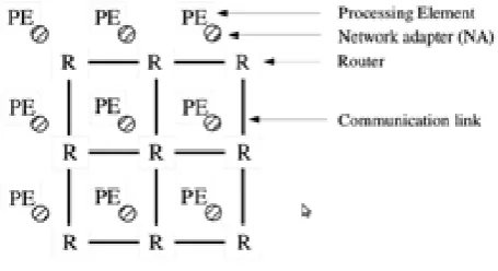
NoC-based system is composed of four basic components: computational resources in the form of Processing Elements (PEs), network adapters (NAs) that implement the interface by which PEs connect to the network, routing nodes (routers) that route data based on a chosen protocol, and links that connect routing nodes and provide a raw communication bandwidth. An IP can be a microprocessor, a DSP, a memory unit, a microcontroller, or any other IP module that can be implemented on a chip. Network adapters are used to interface the IP core to the network and to make communication services transparently available with a minimum effort from the IP core. Routers are responsible for exchanging the data between PEs. Each router has a set of ports, which are used to connect the router to the network. From the router perspective, routing is the mechanism that chooses an output port for a message arriving at an input port. The links that connect routing nodes may consist of one or more logical or physical channels.
NoC STRUCTURE
Fig. 1 shows a sample NoC constructed using a 3 x 3 mesh topology. Instead of using dedicated buses from point to point, a more general scheme is adapted by employing a grid of routing nodes spread out across the chip. These nodes are connected by communication links. In this network topology, each PE is connected to a router through an NA in a 1:1 ratio, whereas routers are connected in a mesh form.
[image:2.595.321.549.428.552.2]A. Networks-on-Chips: A Graph-Theoretic Approach:
Figure. 1 shows a sample NoC constructed using a 3 x 3 mesh topology.
The topological structure of any interconnection network can be represented by a graph. Then, using graph theory concepts, we can analyse the performance of the interconnection network from different perspectives.
B. Mesh:
unidirectional links between two switches or between a switch and a resource.
Fig. 2: Eleven standard NoC topologies: (a) Mesh. (b) Torus. (c) Folded Torus. (d) Ring. (e) Octagon (Oct). (f) Spidergon (Spider). (g) Binary tree
(BT). (h) Butterfly Fat Tree (BFT). (i) SPIN. (j) Hypercube (Hcube). (k) Star. (Routers are represented by white circles, whereas PEs are represented by dark squares.) Fig 2 shows eleven standard NoC topologies.
For my paper I am consider the Mesh & Torus topologies.
VI. NETWORK SIMULATOR NS-2
NS-2 is an object-oriented, discrete event driven network simulator developed at UC Berkely and written in C++ and Object Oriented Tcl (OTcl). NS-2 is a very common tool used for simulating local and wide area networks. It implements network protocols such as TCP and UDP, traffic source behavior such as FTP, Telnet, Web, Constant bit rate (CBR) and Variable bit-rate (VBR); router queue management mechanism such as Drop Tail, Random Early Detection gateways (RED) and Class Based Queuing (CBQ), routing algorithms such as Dijkstra, and a lot more. NS-2 also implements multi-casting and some of the Media Access Control (MAC) layer protocols for LAN simulations. The simulator is open source, hence, allowing anyone and everyone to make changes to the existing code, besides adding new protocols and functionalities to it. This makes it very popular among the networking community which can easily evaluate the functionality of their new proposed and novel designs for network research. The simulator is developed in two languages: C++ and OTcl1. C++ is used for detailed implementations of protocols like TCP or any customized ones. TCL scripting, on the other hand, is the front-end interpreter for NS-2 used for constructing commands and configuration interfaces. For example, if you want to develop a new routing protocol, you have to write it in C++ and add it into the NS-2 library. In order to check the functionality of this protocol, you use TCL scripting through which you can create the required topology, define parameters for links and nodes, and perform simulations to realize your own protocol in action. The interest of NoC researchers in computer networks clearly shows that there is a great deal of resemblance between the two domains. Computer networks have been at the core of research for decades and are still progressing at a very high pace.
Similarly, a significant
VII.
amount of work is being done in parallel computing are which is considered as the parent domain for NoCs. Design paradigms and protocols that are obsolete in networks (or the Internet) can be a good choice for NoCs because of their size and regular structure. However, besides the similarities, there are certain differences between the networks and NoCs due to which
various design choices for NoCs need to be re evaluated. Following is a brief description of both similarities and differences between computer networks and NoCs. Besides above-mentioned functionality of NS-2, a Network AniMator (NAM) is also provided with NS-2 in order to visualize and interact with the system at run-time. Finally, graphs can be created from the produced results to evaluate and analyze the performance of the system Network .
A. Default and defined values :
VII.TRAFFIC SCENARIO GENERATING IN NS-2
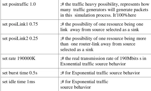
There are two big groups default and defined values for traffic scenario generating. One involves the application of local communication including posiLink1, posiLink2. Another involves the traffic source behavior application, including rate, burst time, idle time.
Table 1; Default and de ned values for traffic scenario generator
set positraffic 1.0 ;# the traffic heavy possibility, represents how many traffic generators will generate packets in this simulation process. It'100%here
set posiLink1 0.75 ;# the possibility of one resource being one link away from source selected as a sink
set posiLink2 0.25 ;# the possibility of one resource being more than one router-link away from source selected as a sink
set rate 190000K ;# the real transmission rate of 190Mbits s in Exonential traffic source behavior
set burst time 0.5s ;# for Exponential traffic source behavior
set idle time 1ms ;# for Exponential traffic source behavior
Four parameters define Exponential traffic source behaviour, which are
a. pktSize- the constant size of the packets generated b. burst time - the average "on" time for the generator c. idle time - the average "off " time for the generator d.
VIII.
rate- the sending rate during a period of "on" time
Following evaluation parameters has been selected for performance evaluation of Network on Chip architectures
SIMULATION ENVIRONMENT
a. Throughput (TP): It is the rate at which a network sends or receives data or amount of data that is transferred over a period of time. It is measure of the channel capacity of a communications link, and connections [9].
TP = (Number of IP) x (Total Time)
(Total messages compeleted) x (Message Length)
Where total messages completed refers to the number of whole messages that successfully arrive at their destination IPs, Message length is measured in flits, Number of IP blocks is the total number of IP blocks present in the system, Total time is the time (in clock cycles) that elapses between the occurrence of the first message generation and the last message reception [7].
[image:3.595.313.564.283.434.2]of time between the start of an action and its completion. Latency can be affected by interconnecting devices.[8] it is fundamental measures of network performance.
[image:4.595.322.558.60.270.2]Li = Sender Overhead + Transport Latency + Receiver Overhead
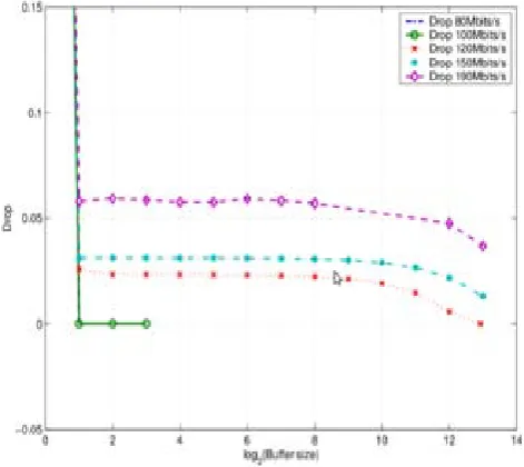
Figure 3 Drop possibility vs communication load
IX.
Evaluating the performance of communication among resources in the whole system,I got lots of original simulation results, including tracefile, NAM tracefile, bandwidth monitor tracefile, and queue monitor tracefile. Some interesting parameters, comparings and gures are listed below.
SIMULATION RESULT
a) Drop possibility vs. Load of NOC b) Delay in message vs. Buffersize
A. Drop possibility vs. Communication load:
We have known drop possibility is not sensitive to buffer size for bigger buffer size from Figure 3 shows out the relation between drop possibility and communication load. The drop possibility is significantly sensitive to the communication load in the range of buffer size from 21 pkts to 25 pkts. The communication load corresponding to rate with 100Mbits s. 120Mbits s, 150Mbits s and 190Mbits s are considered in the figure 3.
B. Delay in message vs. buffer size:
We can conclude from figure 4 that delay in message is not very sensitive to communication load when there have been many packets dropped. The evaluation is only made for Mbuffer size with 4, 8, 16, 32, 64 pkts and different lines correspond to different Mbuffer sizes. When there is no packet dropped (rate =100Mbits s or communication load = 0.302), the delay in messages for different buffer sizes are all 364 ns. Once there are some packets dropped (from the points of rate=120Mbits s/communication load = 0.356) possibility vs communication load.
Figure 4: Delay in message vs. Buffer size Figure 3 Drop
X. CONCLUSION
Networks-on-chip (NoC) are emerging as a viable interconnect architecture for multiprocessor SoC platforms. In this new paradigm, infrastructure IPs is used to establish the on-chip communication medium. NoC based architectures are characterized by various trade-offs with regard to functional, structural, and performance specifications. We went through studying literature, comparing and analysing to make decision for simulator, and determining ns-2 to be used here to model a small scale and simple "network", NOC. All the simulation results can be explained in theory. It also proves that ns-2 is suitable here. In addition, each part of the simulation modeling can map the corresponding functional blocks in NOC very well.
The following series of simulation results were got: a. Increasing buffer size does not make an obvious
advantage for decreasing the number of drop packets b. The drop possibility is more sensitive on
communication load than buffer size in the range of small buffer size
c. Different case has different buffer utilization scenario d. The reasonable buffer size is around 4 or 8 pkts e. Delay in queue is important part for delay in message.
Therefore, delay in message is more sensitive to buffer size than communication load.
XI. ACKNOWLEDGMENT
I owe a great many thanks to a great many people who helped and supported me during the writing of this seminar. My deepest thanks to Prof. Dr. G. R. Bamnote , the Guide of the project for guiding and correcting various documents of mine with attention and care. He has taken pain to go through the seminar and make necessary correction as and when needed.
[image:4.595.48.280.128.334.2]people at Department of Computer Science& Engineering. PRMIT&R, Badnera., for their support.
I would also thank my Institution and my faculty members without whom this project would have been a distant reality. I also extend my heartfelt thanks to my family and well wishers.
XII. REFERENCES
[1]. Haytham El Miligi “Networks-on-Chips: Modeling, Analysis, and Design Methodologies” ph.D Thesis2011
[2]. P.P. Pande, Student Member, IEEE, Cristian Grecu, Michael Jones, Andr Ivanov, Senior Member, IEEE, and Resve Saleh, Senior Member, IEEE,“Performance Evaluation and Design Trade-Offs for Network-on-Chip Interconnect Architectures” IEEE Transactions on Computers, Vol. 54, No. 8 pp.1025-1040,August 2005
[3]. P.Gehlot, , S.S.Chouhan, “ Performance evaluation of Network on Chip architectures ” International Conference on Emerging Trends in Electronic and Photonic Devices & Systems 22-24 Dec. 2009
[4]. F. Karim, A. Nguyen, and Sujit Dey, An Interconnect Architecture For Networking Systems on Chips, IEEE Micro, vol. 22, no. 5, pp. 36-45, Sept./Oct. 2002.
[5]. Yi-Ran Sun, Shashi Kumar, Axel Jantsch, “Simulation and Evaluation for a Network on Chip Architecture Using Ns 2,” Lab of Electronics and Computer Systems (LECS),the Department of Microelectronics & Information Technology (IMIT), Royal Institute of Technology (KTH), Stockholm, Sweden.
[6]. W. Zhang, L. Hou, L. Zuo , Z.Peng, W.Wu, “A Network on Chip Architecture”
[7]. Eitan Altman and Tania Jimenez ,”NS simulators for beginners”, University Los Andes, Venezuela 4 December 2003
[8]. LBNL Network Simulator, http://www-nrg.ee.lbl.gov/ns/
[9]. Simon Thompson.,Haskell - The Craft of Functional Programming, Addison-Wesley, 2 editions, 1999.
[10]. S. Kumar et al., “A Network on Chip Architecture and Design Methodology,” Proc. Int’l Symp. VLSI (ISVLSI), pp. 117-124, 2002.
[11]. W.J. Dally and B. Towles, “Route Packets, Not Wires: On-Chip Interconnection Networks,” Proc. Design Automation Conf. (DAC), pp. 683-689, 2001.
[12]. H. Elmiligi, A. Morgan, M. W. El-Kharashi, and F. Gebali, “Power-Aware Topology Optimization for Networks-on-Chips,” in Proceedings of the IEEE International Symposium on Circuits and Systems (ISCAS’08), Seattle, WA, USA, May 18–21, 2008, pp. 360–363
[13]. Kevin Fall, The ns Manual, the VINT Project a Collaboration betwee researchers at UC Berkeley”, LBL, USC/ISI, and Xerox PARC, Editor Kannan Varadhan, Editor October 4, 2008
[14]. P.P. Pande, C.Grecu, M. Jones, A.Ivanov, “Performance Evaluation and Design Trade-Offs for Network-on-Chip Interconnect Architectures ”IEEE Transactions on Computers, vol. 54, no. 8, August 2005
[15]. Haytham El Miligi “Networks-on-Chips: Modeling, Analysis, and Design Methodologies ”A Dissertation Submitted in Partial Fullfillment of the Requirements for the Degree of Doctor of Philosophy
[16]. Yi-Ran Sun “Simulation and Performance Evaluation for Networks on Chip” Master of Science Thesis 17,December 2001