Available online:
https://edupediapublications.org/journals/index.php/IJR/
P a g e |2641
Power Factor Improvement and Speed Control of SRM Drive Closed
Loop
B. Um a Dev i M-tech Student Scholar
Department of Electrical & Electronics Engineering, KLR Of College Engineering &,technology,paloncha,
Bhadradri Kothagudem(Dt); T elangana, India
V. Nar esh Kum ar Assistant Professor
Department of Electrical & Electronics Engineering, KLR Of College Engineering &,technology,paloncha,
Bhadradri Kothagudem (Dt); T elangana, India
Abstract: This concept deals with an input power quality imp rovement in an Asymmetric Converter based switched reluctance motor (SRM) d rive at ac mains using a Reactor circuit. Normally an asymmetric converter is used as a power converter for SRM d rive. Conventionally three phase ac mains fed bridge rectifier is used as a dc source to feed this power converter which produces high content of harmonics at ac mains with a very low power factor. The proposed circuits with an asymmetric converter fed SRM drive enhance the power factor at ac mains with lo w current harmon ics. By this method we can get almost constant dc link voltage which can be applied to the converter. The proposed SRM drive is modeled and its. The perfo rmance of the reactor circuit topology is co mpared with a conventional SRM drive to demonstrate improved power quality at ac mains. Switched reluctance motors (SRM) are used in number of variab le speed application. This motor is rugged, reliable, requires low maintenance and its fault tolerant. The main dis advantage of this motor is that it requires power converters for its operation. Many types of power converters for SRM drive are reported in the literature. These converters need stable dc supply for its operation. Various converter topologies are available to energize the phase of the SRM but most effective & co mmonly used topology is two switched per phase asymmetric converter. There are many converter topologies are published in the literature. The objectives of the topologies are to reduce the number of switches per phase, reduce the cost of converter and firing circuit. The performance of p roposed reactor circuit fed SRM drive has been compared with the conventional DBR based SRM drive. This concept can be imp lemented by further by improv ing the PF and speed control of
SRM Drive perfo rmance is simulated in
Matlab/Simulink environment I INTRODUCTION
Switched reluctance motors (SRM ) are used in number of variable speed application. This motor is rugged, reliable, requires low maintenance and its
fault tolerant. The main disadvantage of this motor is that it requires power converters for its operation. Many types of power converters for SRM drive are reported in the literature [1]. These converters need stable dc supply for its operation. Various converter topologies are availab le to energize the phase of the SRM but most effective & co mmon ly us ed topology is two switched per phase asymmetric converter. There are many converter topologies are published in the literature. The objectives of the topologies are to reduce the number of switches per phase, reduce the cost of converter and firing circuit [3]. F o r the simp licity and to get full flexib ility in simulation of SRM drive the asymmetric convertor topology is used. The main d rawback of this configuration is that the supply current drawn has high content of harmonics with very low input power factor. The supply current can be made sinusoidal by circulating third harmonic current through ac side of the diode bridge rectifier. The third harmonic current is generated by modulating dc link current and feed back through ac side of diode bridge rectifier by current injection network. The proposed topology for SRM drive system is capable of imp roving the power factor ity with lo w Total Harmonic Distortion (THD) of supply current and keeps the dc link capacitor voltage almost constant.
II SYSTEM CONFIGURA TION
For proposed rector circuit are the combination of a resistor, a transformer & an inductor. The proposed circuit is shown in fig.1. The input supply nature is 3-phase ac source, having ea, eb & ec are the concerned phase voltages & eab, ebc &eca are the corresponding
Available online:
https://edupediapublications.org/journals/index.php/IJR/
P a g e |2642
Fig. 1. Basic structure of a proposed reactor circuit
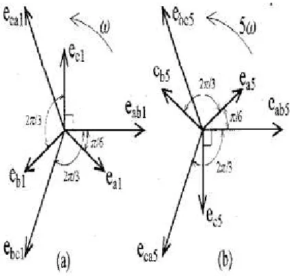
Fig. 2. Phasor diagrams of the fundamental and the 5th harmonic component of the voltage (a) is a phasor diagram of the fundamental voltages, and (b) is that of 5th harmonic voltages
Fig.3 Basic structure for SRM drive with one phase excitation III OPERA TION PRINCIPLE OF A REA CTOR
CIRCUIT
The basic structure of the proposed reactor circuit is shown in fig 1. Which are going to introduced between 3-phase ac source & the Switched Reluctance Motor drive. The circuit includes a series connected inductor (L), a transformer (T) & resistor (R). The phase sequence of the 3-phase ac source is eaebec. The reactor circu it transformer has primary
winding (N), which is connected across the line
voltage eab & secondary winding (n) is connected to a
phase ec. The inductance is connected between
phase-a &phase-amp; primphase-ary winding similphase-arly the resistphase-ance is connected between the phase-c & secondary winding. The currents in the winding N & n are iN & in
respectively. The output voltage E0 will obtained
across the output terminals as the phase voltages & line voltages of fundamental & 5th harmonic
components are shown. In this diagram ea1, eb1 and
ec1 indicates the phase voltages, and eab1,ebc1 and eca1
indicates the line voltages. Similarly the ea5, eb5 and
ec5 indicates the phase voltages, having the phase
order of ea5ec5eb5, and eab5 , ebc5 and eca5 indicates the
line voltages. In the angular frequency of ω rad/sec in the direction of arrow with phase sequence of ea1eb1ec1 & fig-2(b) the angular frequency of 5 ω rad/sec in the s a m e direction with the phase sequence of ea5eb5ec5. By the anlaysis of fig-3.2 we
can conclude that the phase angle between ecl with eabl
& ec5 with eab5 are π/2 rad but there is an difference
the nature i.e. ecl leads eabl & ec5 lags eab5. The voltage
eab is the phasor sum of eabl and eab5 similarly ec is the
phasor sum of ecl and ec5 When there is a 5th
harmonic co mponent induced voltage ec5 supplies a
current iN in series connected inductor, this will
compensate the 5th harmonic co mponent of e0
because eab5 is cancelled by the induced voltage of
inductance L due to the current iN.
Available online:
https://edupediapublications.org/journals/index.php/IJR/
P a g e |2643
After applying the proposed configuration, if we consider that the amplitude of fundamental voltage of
eab be E1 and 5th harmonic voltage of eab be E5 then
as per the pharaoh diagram the equation of eab & ec
are as follows
(1)
(2)
Furthermore, if we assume that the characteristics of the elements like transformer T and the inductance L are having ideal characteristics, then the next step
equations are formulized
in the circuit as
(3)
(4)
(5)
By applying equation (3) to (5), and assume that there are two constants coefficients are K=n/N and τ= L/R. If we include them than the in next equations are as redefined as
(6)
By solving equation (1), (2) and (6), the output
voltage of reactor circuit eo is as follows:
(7)
After the analysis of equation (7), we can conclude that the magnitude of 5th harmonic voltage of eo are depends on the magnitude of coefficient τ & k. The 5th harmonic co mponent of eo can be zero by using the proper values of the variab les. So by
using this specific feature we can remove the 5th harmonic voltages of 3-phase ac source.
3.4 PROPOSED SYSTEM BLOCK DIAGRAM
Fig.5 Proposed SRM drive with reactor circuit
The proposed scheme for the SRM drive fed by a new reactor circu it based PFC converter shown in Fig.5.The front end proposed reactor circuit suppress the 3rd & 5th harmonics fro m current drawn by the
drive. An asymmetric machine converter is connected between universal DBR and Switched reluctance motor. A h igh frequency MOSFET of suitable rating is used in the machine converter for its high frequency operation whereas an IGBT’s (Insulated Gate Bipolar Transistor) are used in the VSI for low frequency operation. The proposed scheme maintains high power factor and low THD of the AC source current while controlling rotor speed equal to the set reference speed.
V. SIMULATIONS RESULTS
Available online:
https://edupediapublications.org/journals/index.php/IJR/
P a g e |2644
Fig 7 Matlab/Simulink wave form of current, torque and speed conventional srm drive without pf
Fig 8 FFT Analysis srm drive without power factor
Fig 9 Matlab/Simulink circuit of conventional srm drive with power factor
Fig 10 Matlab/Simulink circuit wave form of current, torque and speed conventional srm drive with pf
Available online:
https://edupediapublications.org/journals/index.php/IJR/
P a g e |2645
Fig 12 Matlab/Simulink circuit of proposed closed loop srm drive with power factor
Fig 13 Matlab/Simulink circuit wave form of current, torque and speed conventional srm drive with closed loop
CONCLUSION
The proposed reactor circuit fed asymmetrical converter-based Switched reluctance motor drive has been designed and modeled in MATLA B/Simu link environment. The performance of proposed reactor circuit fed SRM d rive has been compared with the conventional DBR based SRM drive. The proposed circuit has reduced the THD of supply current to less than 5%. The ripples in dc lin k voltage have been found negligible and the voltages across the capacitors are observed to be almost constant which is needed for the proper operation of the SRM. The power factor at the front end side has been also near to unity for different value of the source voltages. The THD of ac supply current have been maintained within IEEE- 519 standard with a high power factor.
REFERENCES
[1] S. Vu kosavic and V.R. Stefanovic, “SRM Inverter Topologies: A Co mparative evaluation”, IEEE Trans. On Industry Applications, vol. 27, no. 6, pp 1034-1047, Nov/Dec 1991.
[2] Pollock and B.W. Williams, “Power converter circuit for switched reluctance motors with the minimu m number of switches” in Proc. Inst. Elect. Eng., vol. 137, pt. B, no. 6, 1990, pp. 373-384. [3] Neto, R.M.F., Tofo li, F.L., de Freitas, L.C., “A high power factor half bridge double boost converter without commutation losses”, IEEE Trans. Ind. Electron., 2005, 52, (5), pp. 1278-1285.
[4] Mohan N., Undeland, T.M., Robbins, W.P.: “Power Electronics: Converters, applications and design” (John Wiley & Sons, 2007), p.493.
[5] S. Okanuma and A. Hayasaka, “A new reactor
circuit to remove the 5th harmonic voltage of a
three-phase circuit”, IEEE Transaction on Magnetics, Vo l. 33, No: 5, September 1997, Page(s): 3328-3330. [6] IEEE Gu ide for harmonic control and reactive compensation of static power converters, IEEE Standard 519-1992.
A UTHOR’S PROFILE
BHUKYA UMA DEVI received
B.Tech degree in Electrical and Electronics
Engineering fro m Abdulkalam Institute of
Technological Sciences, Vepalagadda, khammam, Kothagudem, Telangana. And currently pursuing M.Tech in Power Electronics & Electrical Drives at KLR Co llege of Engineering& Technology, Paloncha, Bhadradri Kothagudem,T.S. My areas of interest are Power Systems, and control systems, Electrical Machine.
Available online:
https://edupediapublications.org/journals/index.php/IJR/
P a g e |2646
Dr.P.SurendraBabu is currently working as Professor and Head of Electrical and Electronics Engineering Department at the KLR Co llege of Engineering & Technology, Paloncha, Telangana. He obtained his Ph.D Deg ree in Electrical Engineering in the power Electron ic Devices applied to Po wer Systems fro m JNTU college of Engineering, Kakinada, Andhra Pradesh. He has an Experience of over 14 Years in teaching,undergraduate and Post Graduate classes in the areas of Electrical Machines, Power Systems, Power Electronics and Applications, Network Theory, Drives and etc, as a taken of his credit. He has contributed over 54 papers in various