2
ndInt. Workshop
Irradiation of Nuclear Materials: Flux and Dose Effects
November 4-6, 2015, CEA – INSTN Cadarache, France
The Jules Horowitz Reactor Research Project: A New High Performance
Material Testing Reactor Working as an International User Facility – First
Developments to Address R&D on Material
Gilles BIGNAN
1, Christian COLIN
1, Jocelyn PIERRE
1, Christophe BLANDIN
1,
Christian GONNIER
1, Michel AUCLAIR
2, Franck ROZENBLUM
21
CEA-DEN-DER, JHR Project (Cadarache, France)
2
CEA-DEN-DRSN, Service d'Irradiations en Réacteurs et d'Etudes Nucléaires, SIREN (Saclay, France)
The Jules Horowitz Reactor (JHR) is a new Material Testing Reactor (MTR) currently under construction at CEA Cadarache research center in the south of France. It will represent a major research infrastructure for scientific studies dealing with material and fuel behavior under irradiation (and is consequently identified for this purpose within various European road maps and forums; ESFRI, SNETP…). The reactor will also contribute to medical Isotope production.
The reactor will perform R&D programs for the optimization of the present generation of Nuclear Power Plans (NPPs), will support the development of the next generation of NPPs (mainly LWRs) and also will offer irradiation capabilities for future reactor materials and fuels.
JHR is fully optimized for testing material and fuel under irradiation, in normal, incidental and accidental situations:
with modern irradiation loops producing the operational condition of the different power reactor technologies ;
with major innovative embarked in-pile instrumentation and out-pile analysis to perform high-quality R&D experiments ;
with high thermal and fast neutron flux capacity and high dpa rate to address existing and future NPP needs.
JHR is funded and steered and will be operate as an international user-facility open to international collaboration. This lead to the following topics:
the existence of an international consortium gathering the funding organizations to steer the project ;
the setting-up of an international scientific community around JHR through seminars, working groups to optimize the experimental capacity versus future R&D needs ;
the preparation of the first JHR International Program potentially open to non-members of the JHR consortium.
It will answer needs expressed by the scientific community (R&D institutes, TSO…) and the industrial companies (utilities, fuel vendors…). Consequently, the JHR facility will become a major scientific hub for cutting edge research and material investigations (multilateral support to complete cost effective studies avoiding fragmentation of scientific effort, access to developing countries to such state of the art research reactor facilities, supra national approach….).
Considering material behavior under irradiation, such studies is most of the time associated with a complex multi-physical modelling of the materials’ behaviors. It requires well controlled and instrumented irradiation experiments in material testing reactors.
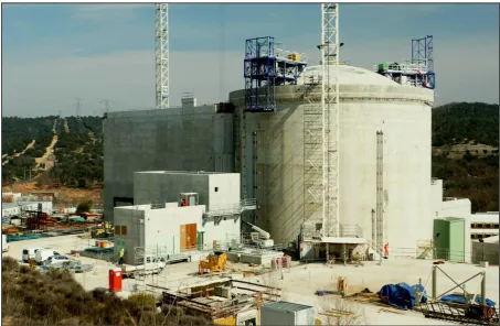
This paper gives an up-to-date status of the construction (Fig. 1) and of the developments performed to build the future experimental capacity dedicated to the material irradiations in JHR reactor. In-core and in reflector devices will be presented (Fig. 2), corresponding to large ranges of temperature and neutrons flux for the irradiation conditions. A special attention focuses on the improvement of the thermal stability and gradients of the interest zones in samples despite strong gamma heating and on
EPJ Web of Conferences 115, 01003 (2016) DOI: 10.1051/epjconf/201611501003
© Owned by the authors, published by EDP Sciences, 2016
2
ndInt. Workshop
Irradiation of Nuclear Materials: Flux and Dose Effects
November 4-6, 2015, CEA – INSTN Cadarache, France
2
an improvement of the instrumentation devoted to the experiments. Some specific devices in support of LWR type reactors will be described such as equipment designed for the qualification of Reactor Pressure Vessel (RPV) steels, for the study of the stress corrosion cracking assisted by irradiation phenomena (IASCC), or for the studies of creep-swelling of structural materials.
Fig. 1: General view of the JHR building (September 2015).
Fig. 2: reactor pool (left) and part a reactor block (right) of the JHR (September 2015).
References
The Jules Horowitz Reseach Reactor Project
A New High Performance Material Testing Reactor
working as an International Facility:
First Developments to address R&D on Material
2
ndInternational Workshop MINOS, November 4-6 2015, Cadarache
G. BIGNAN
(1)|
C. COLIN
(2)|
J. PIERRE
(2)|
C. BLANDIN
(2)|
C. GONNIER
(2) )|
M. AUCLAIR
(3)|
F. ROZENBLUM
(3)[email protected] ; [email protected]
(1) CEA Cadarache: DEN / DER
(2) CEA Cadarache: DEN / DER / SRJH
MTR allows to reproduce on
a small scale, real power plant
conditions and in some cases,
more severe conditions for
Material screening
(comparison of materials
tested under representative conditions)
Material characterisation
(behaviour of one material in a wide
range of operating conditions, up to off-normal and severe conditions)
Fuel element qualification
(test of one / several fuel rods (clad+fuel))
Next Step in MTR:
JHR: a future Reference International User Facility
2nd International Workshop MINOS, November 4-6 2015, Cadarache | PAGE 3
Motivation of JHR :
An Ageing fleet of MTR in Europe
HBWR
HFR
BR2
OSIRIS
LVR-15
MARIA
JHR
Under construction
Age of current E.U. main
MTRs
in 2015 (years)
2nd International Workshop MINOS, November 4-6 2015, Cadarache | PAGE 4
1)
R&D in support to nuclear Industry
Safety and Plant life time management (ageing & new plants)
Fuel behavior validation in incidental and accidental situation
Assess innovations and related safety for future NPPs
2) Radio-isotopes supply for medical application
MOLI production
JHR will supply 25% of the European demand
(today about 8 millions protocols/year)
and up to 50% upon specific request
3) A key tool to support expertise
Training of new generations (JHR simulator, secondee’s program)
Maintaining a national expertise staff and credibility for public acceptance
Assessing safety requirements evolution and international regulation
harmonisation
JHR 3 MAIN OBJECTIVES
JHR CONSORTIUM & GOVERNING BOARD
JHR Consortium current partnership: Research centers & Industrial
companies
IAEC
Associated Partnership:
19/03/2007 Signature of the JHR
consortium
In some cases, the organization (member of the JHR consortium) is itself the
representative of a national domestic consortium which gathers organizations
among industry, academics, R&D organizations, TSO, or Safety Authority
2nd International Workshop MINOS, November 4-6 2015, Cadarache | PAGE 7
Governing Board
(JHR Consortium Members)
CEA
(Nuclear Operator)
JHR Reference Operation Plan (4 years plan)
For Members of the Consortium and Non-Members
Proprietary Programs
Joint international
Programs(open to
non-members)
&
JHR : an International Users Facility
Nuclear safety ; Technical and
Economical performance (operation cost)
Project leader appointment
Validation of operation plan, business
strategy, economy of the project
Operation plan fulfilment
programs definition (preparation of next
Preparing JHR
International Community:
- The yearly seminar
- The 3 Working Groups
- The Secondee Program
- The recent ICERR
Preparing JHR International Community:
-
The yearly scientific and technical seminar
: possible participation
for some non-members (5
th
April 2015-next one embedded with
NUGENIA forum-April 2016)
-
3 Working Groups :
- Fuel R&D topics
- Material R&D topics
- Technology issues for experimental devices
-
Secondee Program
JHR International User Facility
-
Compliance
between future
R&D needs
and first
experimental
capacity
-
Preparation of
first JHR
programs
2nd International Workshop MINOS, November 4-6 2015, Cadarache | PAGE 10
CEA FIRST DESIGNATED ICERR BY THE IAEA (SEPTEMBER 2015) :
INTERNATIONAL CENTERS BASED ON RESEARCH REACTORS
Create international scientific networks
Make available facilities and experience of mature R&D centres in the field of
peaceful uses of Nuclear Energy to affiliates
Lead innovative joint programs with shared results
Host international scientists / engineers
Provide “hands on” nuclear education “in the field”
R&D
Expertise
AFFILIATES
JHR and
Ancillary
Facilities
CEA offer within IAEA/ICERR centered on futur JHR
and its ancillary facilities
Saclay
Cadarache
ISIS
:
Education
&Training
LECA
:
Hot Lab on Fuel
- R&D Projects
- Hands-On Training
(Equipments)
LECI
: Hot Lab on
Materials
- Hands-On Training
(Equipments)
- R&D Projects
ORPHEE
:
Neutron
beams
- Hands-On Training
(Equipments)
- R&D Projects
JHR
:
MTR
-
Hands-OnTraining
-
R&D Projects
EOLE/MINERVE
:
-
Education &Training
-
Hands-On Training
R&D Projects
ZEPHYR : LPR
2nd International Workshop MINOS, November 4-6 2015, Cadarache | PAGE 13
Installation of specific devices for reactor
containment monitoring
Installation of
pre-stressing cables
Reactor building
| PAGE 14
Machining of bottom plug flange
(S12/2015)
Water Box RPP (S12/2015)
REACTOR BLOCK
Beginning of components manufacturing
Water Box REP (S18/2015)
Main vessel
JHR design and performances
First fleet of experimental
Devices under development
| PAGE 16
JHR facility & experimental capacity
I&C: 3 floors, 490 m
2Cubicle: 3 floors, 700 m
2A facility dedicated to experimental purposes :
A modern facility :
►
Large experimental areas
►
Non destructive examination benches
►
Fission Product Laboratory
►
Chemistry Laboratory…
Thermal neutron flux
Fast neutron flux
~20 simultaneous experiments
JHR facility & experimental capacity
A 100 MW High Performances Research Reactor
Material ageing
(up to 16 dpa/y)
In core
Up to 5.5E14 n/cm².s (E> 1 MeV)
Up to 1.E15 n/cm².s (E> 0.1 MeV)
7 small locations (
F
~ 32mm)
3 large locations (
F
~ 80mm)
In reflector
Up to 3.5E14 n/cm².s (th)
Fixed irradiation positions
(Φ100 mm & Φ200 mm)
and on 6 displacement systems
LWR fuel
experiments
+
Material ageing
(low ageing rate)
Reliable Displacements
Systems for Power adjustment,
Power transient tests…
2nd International Workshop MINOS, November 4-6 2015, Cadarache | PAGE 18
JHR facility & experimental capacity:
First fleet of irradiation material devices
Topic Objective Material Instrumentation
Flux
(n.cm-2.s-1) Fluence
(n.cm-2) / dpa Temp. (°C)
Reactor Pressure
Vessel
Dose accumulation Low alloyed
steels Loading 10
11 – 1013 < 2.1020 240 – 320
Internals
Dose accumulation
Stainless steels,
Ni-based alloys 10
12 – 1014 10 – 80 dpa 320 – 390
Environment effect Loading, displacement measurements
Mechanical testing Loading, displacement measurements
Cladding
Mechanical properties
Zr-alloys
SS Loading, displacement < 3. 1014
< 400°C
Accident tolerance
- I
rradiated material behaviour (low dpa rate)
tensile tests, resilience test, crack propagation tests …..
Behaviour of Thermal affected zones
OCCITANE
OCCITANE
2nd International Workshop MINOS, November 4-6 2015, Cadarache | PAGE 19
JHR facility & experimental capacity:
First fleet of irradiation material devices
Topic Objective Material Instrumentation
Flux
(n.cm-2.s-1) Fluence
(n.cm-2) / dpa Temp. (°C)
Reactor Pressure
Vessel
Dose accumulation Low alloyed
steels Loading 10
11 – 1013 < 2.1020 240 – 320
Internals
Dose accumulation
Stainless steels,
Ni-based alloys 10
12 – 1014 10 – 80 dpa 320 – 390
Environment effect Loading, displacement measurements
Mechanical testing Loading, displacement measurements
Cladding
Mechanical properties
Zr-alloys
SS Loading, displacement < 3. 1014
< 400°C
Accident tolerance
OCCITANE
OCCITANE
OCCITANE
MICA / CALIPSO
- I
rradiated material behaviour (high dpa rate)
- Material behaviour under irradiation (mechanical loading)
2nd International Workshop MINOS, November 4-6 2015, Cadarache | PAGE 20
JHR facility & experimental capacity:
First fleet of irradiation material devices
Topic Objective Material Instrumentation
Flux
(n.cm-2.s-1) Fluence
(n.cm-2) / dpa Temp. (°C)
Reactor Pressure
Vessel
Dose accumulation Low alloyed
steels Loading 10
11 – 1013 < 2.1020 240 – 320
Internals
Dose accumulation
Stainless steels,
Ni-based alloys 10
12 – 1014 10 – 80 dpa 320 – 390
Environment effect Loading, displacement measurements
Mechanical testing Loading, displacement measurements
Cladding
Mechanical properties
Zr-alloys
SS Loading, displacement < 3. 1014
< 400°C
Accident tolerance
OCCITANE
OCCITANE
OCCITANE
MICA / CALIPSO
MICA / CALIPSO
MICA / CALIPSO
CLOE
CLOE
LORELEI (fuel)
- Zr alloy corrosion
MICA
:
Material Irradiation CApsule
Based on
OSIRIS
technologies
:
CHOUCA / PHAETON
at least, the same performances
Available at JHR start-up
Experimental volume:
f
24mm x 600mm
Upper volume (instrumentation):
f
24mm x 2400mm (max.)
Lower volume (instrumentation):
f
24mm x 700mm (max)
“Standard” MICA
Static
NaK
coolant
T < 450°C
Many samples
Simplified instrumentation:
thermocouples
Gamme de fonctionnement
0 5 10 15 20 25
0 100 200 300 400 500 600 700 800 900
Température (°C) E c h a u ff e m e n t G a m m a ( W /g g ra p h it e )
He : 0,5mm / Chauff : Min
He : 0,5mm / Chauff : Max
He : 0,25mm / Chauff : Min
He : 0,25mm / Chauff : Max
He : 0,1mm / Chauff : Min
He : 0,1mm / Chauff : Max
Limite Température Basse (250°C)
Limite Réacteur Haute 100MW (16,1 W/g)
Limite Réacteur Haute 70MW (11,3 W/g)
Limite Réacteur Basse 70MW(8,1 W/g)
Limite Fluage Négligeable (450°C)
g h eat in g ( W /g g rap h it e)
Operating range
MICA test device: “Standard” configuration
Investigation of physical properties of material
(vs flux, fluence and temperature) under
high dpa
Samples temperature adjustment:
Gamma heating
Gas gap dimension / nature of gas
Electric heating elements
“Standard” MICA
Static
NaK
coolant
T < 450°C
Many samples
Simplified instrumentation:
thermocouples
“Instrumented” MICA
Static
NaK
coolant
T < 450°C
Specific sample
Evolved instrumentation:
thermocouples, LVDT,
in-situ loading
HT MICA
Static
inert gas
T
> 1000°C
Gen. IV samples
Instrumentation:
to be discussed
MICA
:
Material Irradiation CApsule
Based on
OSIRIS
technologies
:
CHOUCA / PHAETON
at least, the same performances
Available at JHR start-up
Experimental volume:
f
24mm x 600mm
Upper volume (instrumentation):
f
24mm x 2400mm (max.)
Lower volume (instrumentation):
f
24mm x 700mm (max)
MICA test device: “HT” configuration
“Standard” MICA
Static
NaK
coolant
T < 450°C
Many samples
Simplified instrumentation:
thermocouples
“Instrumented” MICA
Static
NaK
coolant
T < 450°C
Specific sample
Evolved instrumentation:
thermocouples, LVDT,
in-situ loading
MELODIE
experiment
Cladding sample
In-situ loading: biaxial stress
(internal pressure +
tensile/compressive load)
Scanning diameter gauge and
elongation during irradiation
MICA
:
Material Irradiation CApsule
Based on
OSIRIS
technologies
:
CHOUCA / PHAETON
at least, the same performances
Available at JHR start-up
Experimental volume:
f
24mm x 600mm
Upper volume (instrumentation):
f
24mm x 2400mm (max.)
Lower volume (instrumentation):
f
24mm x 700mm (max)
MICA test device: “Instrumented” configuration
2nd International Workshop MINOS, November 4-6 2015, Cadarache | PAGE 24
MICA test device: “Instrumented” configuration
MICA
:
Material Irradiation CApsule
MELODIE experiment: ….. To prepare MICA instrumented rigs
Successful tests of the
online measurement of
axial deformations under stress
Prototype exhibited already the breakthrough
capability to measure a creep rate in a week (several months with « cook-and-look »
irradiation devices)
Successful tests of the
offline measurement of diametral deformations
Next step: early 2016 , feedback from this first irradiation campaign,
optimise the device (MELODIE2)
CEA-VTT investigation for possible irradiation capacity within European Partners
On-going qualification of the design with a CALIPSO prototype
First successful tests of the electromagnetic pump
CALIPSO test device
Investigation of physical properties of material under high dpa
Thermodynamic loop integrated within the test device
Heat Exchanger (HE) / Electrical Heater (EH)
Innovative electromagnetic pump (L 450 mm, D 80 mm)
NaK flow
(2 m
3/h)
Improvement of the sample temperature mastering
From 250 up to 450°C (setting of HE & EH parameters)
Δθ < 8°C
(Tmax – Tmin all along the samples stack)
P P
P P P
P P
Pump
(EM)
OCCITANE test device
Investigation of physical properties after
irradiation of NPP pressure vessel steels
under
low dpa
OCCITANE
:
O
ut-of-
C
ore
C
apsule for
I
rradiation
T
esting of
A
geing by
Ne
utrons
Static Helium capsule
Based on the OSIRIS feedback (IRMA test device, 150 irradiation cycles)
Ex-core location
Fixed location
Dose: up to 100 mdpa/y (1 MeV)
Neutron shields
Samples temperature adjustment
230- 300°C
Gamma heating
Gas gap dimension
Electric heating elements
At least, 18 thermocouples, and 45 dose integrators
Equivalent carrying volume: 30x62.5x500mm
3
Helium
gas
230 – 300°C
(furnace with 6 heating zones)
100 mdpa/year
CLOE test device
Need of a corrosion loop to perform integral experiments
India in-kind contribution (DAE-BARC
)
CEA corrosion loops feedback, MTR+i3 European project
LWR conditions: well controlled and adjusted water chemistry, temperatures, …
Fixed location
Ex-core with a large diameter
In-core with a smaller diameter
(taking into account safety aspect)
In-situ measurements: ECP, pH, H2,
load, LVDT, cracking propagation, DCPD
Corrosion loop for LWR conditions
| PAGE 28
JHR facility & experimental capacity:
JHR vessel surveillance program
2nd International Workshop MINOS, November 4-6 2015, Cadarache
•
The vessel is important for safety (2
ndnuclear barrier)
•
The vessel material (Al 6061) will degrade with time and
irradiation
•
Therefore we need to understand the change in material
properties
•
The JHR conditions (spectrum) will be unique, therefore
need SURVEILLANCE SAMPLES
•
Aluminium is susceptible to damage by both thermal (via
transmutation) and fast (via DPA) neutrons.
•
Therefore need samples both sides of the vessel
•
Inside Core (high flux – PROSPERI), outside core (low
energy flux – PROSPERO)
0 0.05 0.1 0.15 0.2 0.25
1.0E-09 1.0E-07 1.0E-05 1.0E-03 1.0E-01 1.0E+01
E [MeV] 1/Le thargy Position 103 Position 101 Position C313 SFR core reference
Fast flux
Thermal flux
2nd International Workshop MINOS, November 4-6 2015, Cadarache | PAGE 30
FP laboratory:
dedicated to on-line FP measurement
Cubicle :
Control of Thermo-hydraulic conditions and water treatmentQuantitative online gamma spectrometry
reservation
Piping
penetration
FP piping
penetration
Connection
lines
Reactor
vessel
Test device
Displacement system
I&C rooms for loop
+ test device
Core
Material and fuel irradiation needs
in the nuclear industry
Qualification
Characterisation
Selection
-
Main objectives
Basis irradiation of several
innovative products under similar
conditions
- Main requirements
High embarking capacity
Few instrumentation
Post irradiation examination
- Main objectives
Measurement of physical properties
under neutron flux
Investigation of: Burn-up effect /
Fission gas release / Pellet-Clad
interaction / Chemical effect / Creep
phenomena …
-
Main requirements
High instrumentation
Accurate control of environment
conditions
(steady or transient)
Single effect experiments
- Main objectives
Reproduction of environment conditions
of power reactors in normal situation
Envelope situations targeted
-
Main requirements
Good representativity of power reactor
(steady and transient states)
Long term or short term irradiations
- Parametric irradiations
ex: Microstructure effect experiments
Summary for normal conditions
Technical goals
• Study of LWR cladding irradiation creep
• Real time control of the biaxial stress
+ online measurement of the biaxial creep
OSIRIS environment
• Sample holder in a CHOUCA capsule Similar to MICA capsule
• 350 °C, static NaK coolant Similar to MICA capsule
Biaxial stress controlled in real time
• Specimen pressurization Max pressure 160 bar
• Push-pull axial loading unit
• Hoop Stress limit: sӨ = 120 MPa, Axial stress limit: sz = 180 MPa
Online biaxial measurement of creep strain
• Continuous measurement of axial strain with a 5-wire LVDT
• Periodical measurement of hoop strain with a diameter gauge (DG) LVDT Traction bellows Compression bellows Zy-4 90mm cladding tube Diameter gauge LVDT Traction bellows Compression bellows Zy-4 90mm cladding tube Diameter gauge
MICA test device: “Instrumented” configuration
MICA
:
Material Irradiation CApsule
MELODIE experiment: a challenging experiment in OSIRIS…
….. To prepare MICA instrumented rigs
2nd International Workshop MINOS, November 4-6 2015, Cadarache | PAGE 33
MICA test device: “Instrumented” configuration
2nd International Workshop MINOS, November 4-6 2015, Cadarache | PAGE 34
MICA test device: “Instrumented” configuration
MICA
:
Material Irradiation CApsule
CALIPSO test device
P P
P P P
P P
Pump
(EM)
Fluid control panel
Handling cask
Operating
plateform
Good behavior of the components
(electromagnetic pump, heat exchanger, heater)
| PAGE 35
SOPRANO Facility :
| PAGE 36
Gamma and X-Ray
tomography systems
Multipurpose test benches
LINAC (X)
g-detector Shielding
XR-detector
Tunablegfront collimator Device
Side cutaway
Pool bank fixing
Penetration X-table Y-table Bench Z-table XR-collimator
View from the core