1472 | P a g e
ON-CHIP PERMUTATION NETWORK IN
MULTIPROCESSOR SYSTEM ON-CHIP FOR
ADDRESSING PERMANENT ERRORS
Akilandeswari R
1, Rashmi B
2 12Assistant Professor, Department of Electronics, Sindhi College, Bengaluru (India)
ABSTRACT
This paper presents the design of on-chip permutation network to support traffic permutation and an adaptive
system for detecting and bypassing permanent errors in on-chip interconnects. Without interrupting the data
flow this system employs pipelined circuit-switching approach with dynamic path setup which reroutes the data
to a set of spare wires on erroneous links .If there is any change in permutation dynamic path set up scheme
supports run time path arrangement. The multistage network topology detects permanent errors at runtime. The
circuit-switching offers a guarantee of permuted data and enables the benefit of stacking multiple networks.
In-Line Test (ILT) using spare wires and test pattern generator is proposed.
Keywords: Permutation, Pipelined Circuit Switching, Multistage Network, In-Line Test (ILT)
I.
INTRODUCTION
As the number of the elements and transactions among cores of the Multiprocessor SoC (MPSoC) and Multi
core processor (MCP) increases, the reliability and performance of the system becomes a key design and
implementation issue for large scale system. Fault may be either transient or permanent and packet congestion in
the interconnection network is sources for reducing the reliability and performance in a NoC based system. A
fault tolerant and high performance network system provides continuous operation in the presence of faults or
congestions.
Permutation traffic is a traffic pattern where each input sends traffic to exactly one output and each output
receives traffic from exactly one input, is one of the important traffic classes exhibited from on-chip
multiprocessing applications [7], [8].
In order to maintain coding strength in the presence of permanent errors, spare wires are used to replace
permanently erroneous wires.Spare wires requires the following: 1) reconfiguration control and logic to replace
the erroneous wires and 2) a protocol for synchronizing information between receiver and transmitter. A system
that replaces permanently erroneous wires without any interruption in data flow is designed using spare wires.
To detect permanent errors, In-Line Test (ILT) method to test each adjacent pair of wires in a link for opens and
1473 | P a g e
tested; the ILT method also recovers resources from intermittent errors that were incorrectly flagged aspermanent.
II.
ON-CHIP NETWORK DESIGN
The pipelined circuit-switching approach with a dynamic path-setup scheme supports runtime path arrangement.
The path setup, network topology is done then switching nodes are designed.
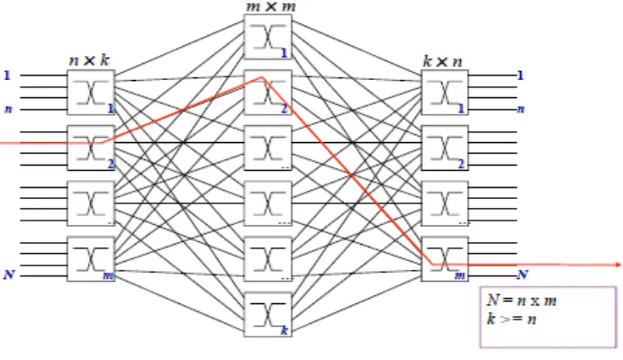
Clos network is a family of multistage networks is applied to build scalable commercial multiprocessors with
thousands of nodes in macro systems [7], [11]. A three-stage Clos network is given as C (n, m,p), where n
represents the number of inputs in each of p first-stage switches and m is the number of second-stage switches.
The advantage of this network is connection between a large number of input and output ports made by using
only small-sized switches. The matching between the ports can be made by configuring the switches in all
stages. In figure n represents the number of sources which feed into each of the m ingress stage crossbar
switches. There exists only one connection between each ingress stage switch and each middle stage switch.
And each middle stage switch is connected to only once to each egress stage switch.
Figure 1: 3-Stages Clos Network
.
To support a parallelism degree of 16 as in MPSoCs [3]–[5], C(4,4,4) is used as a topology for the designed
network. This network can realize all possible permutations between its input and outputs using rearrange able
property.
The three-stage Clos network is used to minimize implementation cost and it enables a rearrange able property
for the network. There are three phases in a pipelined circuit-switching scheme: the setup, the transfer, and the
1474 | P a g e
Figure 2: On-chip network topology2.1. SWITCH INTERCONNECTION
A switch-by-switch interconnection with handshake signals is proposed to support circuit switching. The bit
format of the handshake is 1-bit Request (Req)and a 2-bit Answer (Ans). When an idle link is requested by the
corresponding downstream switch in the setup phase Req=1 is used. It is also kept during data transfer along the
set up path. A Req=0 the switch releases the occupied link. This code is also used in both the setup and the
release phases. The destination is ready to receive data from the source when Ans=01. When Ans=01 the signal
propagates back to the source, denoting that the path is set up, then a data transfer can be started immediately.
When Ans=11(nAck) end-to-end flow control is maintained when the receiving end is not ready to receive data
being busy with other tasks, or overflow at the receiving buffer. An Ans=10(Back) means that the link is
blocked. This Backcode is used for a backpressure flow control of the dynamic path-setup scheme, which is
discussed in the following subsection.
Figure 3: Path-diversity
III. ERROR CORRECTION TECHNIQUES
To identify reliability issues in on-chip interconnects Error control coding (ECC) techniques are used [16]–[22],
but these techniques generally target transient errors rather than permanent errors. A permanent fault can reduce
1475 | P a g e
transient errors; protection against permanent or intermittent errors is rarely discussed. Two recovery techniquesare used when an error on a link has been detected. In Automatic Repeat Query (ARQ), a retransmission is
requested, while in Forward Error Correction (FEC), check bits transmitted together with the data are used to
correct errors without the need for retransmission [24].
3.1 SPARE RESOURCES
The use of spare modules to replace erroneous ones, in array structures, is a long-known fault-tolerant approach
[27]. Spare cells and wires are used in field-programmable gate arrays to bypass defective components
[28],[29]. Refan et al. use spare wires to recover from switch failure by connecting each processing element to
two switches in a network-on-chip (NoC); if a permanent fault occurs in one switch, processing elements share
the working switch, and the system reroutes its data accordingly. Grecu et al. have analysed the use of spare
wires in NoCs to increase manufacturing yield; reconfiguration of the links used crossbar switches with
redundant channels. The presented reconfiguration system uses a synchronous design methodology and FEC to
achieve higher throughput.
3.2. PERMANENT ERROR CORRECTION
Permanent-error correction using spare wires in on-chip network is a two-step process. The permanent error
must be detected first followed by link must be reconfiguration to avoid transmitting over the faulty wire.-
Figure 4: Reconfigurable link system.
The adaptive link framework is shown in Figure and consists of a transmitter, a link, and a receiver. The
incoming -bit-wide data word is encoded in the transmitter to a code word of width, which is transmitted
through the link and decoded in the receiver. Decoder corrects any errors and outputs the original –bit data
word. More number of spare wires is available. Reconfiguration units at the transmitter and receiver determine
the lines carry data and which are left idle. The reconfiguration control units pass the information between the
receiver and transmitter and synchronize reconfiguration.
The error detection and reconfiguration control unitdetects permanent errors and initiates reconfiguration. The
1476 | P a g e
wires under test are needed. The ILT method requires a Test Pattern Generator(TPG) block and test inputs to
produce test signals. The techniques are applied to permanent and intermittent errors in the link; the logic units
are assumed to function correctly.
IV. ILT METHOD
The ILT method routes data sequentially from each pair of adjacent wires to a set of available spare wires,
allowing each pair to be tested for intermittent and permanent faults. This is achieved without interrupting data
transmission, by making use of the reconfiguration system. To protect against runtime permanent errors, the ILT
is run periodically, with a period that can be shortened to improve error or increased energy efficiency. With this
periodic testing, the ILT can be triggered when an error is detected beyond the error correction capability of the
code protecting the link. The trigger can be controlled by an upper protocol layer (e.g., application) to save
energy during idle periods.
V. CONCLUSION
This paper presents an on-chip network design which supports traffic permutation in MPSoC applications. A
reconfiguration system utilizes spare wires for erroneous wires without interfering data transmission. Energy,
latency and throughput are improved considerably. This adaptive system provides tolerance against number of
permanent errors equal to the number of spare wires in the system. A reconfigurable system uses spare wires to
replace erroneous wires and enable reconfiguration without interfering with data transmission h. The results
show that the approach provides tolerance against a number of permanent errors equal to the number of spare
wires in the system.
REFERENCES
[1] S. Borkar, ―Thousand core chips—A technology perspective,‖ in Proc.ACM/IEEE Design Autom. Conf.
(DAC), 2007, pp. 746–749.
[2] P.-H. Pham, P. Mau, and C. Kim, ―A 64-PE folded-torus intra-chip communication fabric for guaranteed
throughput in network-on-chip based applications,‖ in Proc. IEEE Custom Integr. Circuits Conf. (CICC),
2009, pp. 645–648.
[3] C. Neeb, M. J. Thul, and N.Wehn, ―Network-on-chip-centric approach to interleaving in high throughput
channel decoders,‖ in Proc. IEEE Int.Symp. Circuits Syst. (ISCAS), 2005, pp. 1766–1769.
[4] H. Moussa, A. Baghdadi, and M. Jezequel, ―Binary de Bruijn on-chip network for a flexible multiprocessor
LDPC decoder,‖ in Proc. ACM/IEEE Design Autom. Conf. (DAC), 2008, pp. 429–434.
[5] H. Moussa, O. Muller, A. Baghdadi, and M. Jezequel, ―Butterfly and Benes-based on-chip communication
networks for multiprocessor turbo decoding,‖ in Proc. Design, Autom. Test in Euro. (DATE), 2007,pp. 654–
1477 | P a g e
[6] S. R. Vangal, J. Howard, G. Ruhl, S. Dighe, H. Wilson, J. Tschanz,D. Finan, A. Singh, T. Jacob, S. Jain, V.Erraguntla, C. Roberts, Y.Hoskote, N. Borkar, and S. Borkar, ―An 80-tile sub-100-w TeraFLOPS processor
in 65-nm CMOS,‖ IEEE J. Solid-State Circuits, vol. 43, no.
1, pp. 29–41, Jan. 2008.
[7] W. J. Dally and B. Towles, Principles and Practices of Interconnection Networks:. San Francisco, CA:
Morgan Kaufmann, 2004.
[8] N. Michael, M. Nikolov, A. Tang, G. E. Suh, and C. Batten, ―Analysis of application-aware on-chip routing
under traffic uncertainty,‖ in Proc.IEEE/ACM Int. Symp. Netw. Chip (NoCS), 2011, pp. 9–16.
[9] P.-H. Pham, J. Park, P. Mau, and C. Kim, ―Design and implementation of backtracking wave-pipeline switch
to support guaranteed throughput in network-on-chip,‖ IEEE Trans. Very Large Scale Integr. (VLSI)
Syst.,10.1109/TVLSI.2010.2096520.
[10] D. Ludovici, F. Gilabert, S. Medardoni, C. Gomez, M. E. Gomez, P.Lopez, G. N. Gaydadjiev, and D.
Bertozzi, ―Assessing fat-tree topologies for regular network-on-chip design under nanoscale technology
constraints,‖ in Proc. Design, Autom. Test Euro. Conf. Exhib. (DATE),2009, pp. 562–565.
[11] Y. Yang and J.Wang, ―A fault-tolerant rearrangeable permutation network,‖IEEE Trans. Comput., vol. 53,
no. 4, pp. 414–426, Apr. 2004.
[12] P. T. Gaughan and S. Yalamanchili, ―A family of fault-tolerant routing protocols for direct multiprocessor
networks,‖ IEEE Trans. Parallel Distrib. Syst., vol. 6, no. 5, pp. 482–497, May 1995.
[13] V. E. Beneˇs, Mathematical Theory of Connecting Networks and Telephone Traffic. New York: Academic
Press, 1965.
[14] Nguyen, H.N. and Ngo, V.D. and Choi, H.W., “Assessing Routing Behavior on On-Chip-Network,
International Conference on Computer Engineering and Systems, 2006.Pages 62-65, 2006.
[15] G. De Micheli and L. Benini, Networks on Chips: Technology and Tools (Systems on Silicon). San
Fransisco, CA: Morgan Kaufmann, 2006.
[16] D. Bertozzi, L. Benini, and G. De Micheli, ―Error control schemes for on-chip communication links: The
energy-reliability tradeoff,‖ IEEE Trans. Comput.-Aided Des. Integr. Circuits Syst., vol. 24, no. 6, pp. 818–
831, Jun. 2005.
[17] L. Li, N. Vijaykrishnan, M. Kandemir, and M. J. Irwin, ―Adaptive error protection for energy efficiency,‖
in Proc. ICCAD, San Jose, CA, Nov. 2003, pp. 2–7.
[18] S. Murali, T. Theocharides, N. Vijaykrishnan, M. J. Irwin, L. Benini, and G. De Micheli, ―Analysis of error
recovery schemes for networks on chips,‖ IEEE Des. Test Comput., vol. 22, no. 5, pp. 434–442, Sep./ Oct.
2005.
[19] D. Rossi, P. Angelini, and C. Metra, ―Configurable error control scheme for NoC signal integrity,‖ in Proc.
13th IEEE IOLTS, Crete, Greece, Jul. 2007, pp. 43–48.
[20] S. R. Sridhara and N. R. Shanbhag, ―Coding for system-on-chip networks:A unified framework,‖ IEEE
1478 | P a g e
[21] Q. Yu and P. Ampadu, ―Adaptive error control for reliable systems-on chip,‖in Proc. IEEE ISCAS, Seattle,
WA, May 2008, pp. 832–835.
[22] H. Zimmer and A. Jantch, ―A fault model notation and error-control scheme for switch-to-switch buses in a
network-on-chip,‖ in Proc. 1st IEEE/ACM/IFIP CODES+ISSS, Newport Beach, CA, Oct. 2003, pp.188–
193.
[23] T. Lehtonen, P. Liljeberg, and J. Plosila, ―Online reconfigurable self-timed links for fault tolerant NoC,‖
VLSI Des., vol. 2007, pp. 1–13,2007.
[24] R. Ziemer and R. Peterson, Introduction to Digital Communication,2nd ed. Upper Saddle River, NJ:
Prentice-Hall, 2001.
[25] A. Ejlali, B. M. Al-Hashimi, P. Rosinger, and S. G. Miremadi, ―Joint consideration of fault-tolerance,