Experimental Study of Double Point Cutting
Tool on Main Cutting Force during Turning
of Mild Steel
Bar
S.Vanangamudi
1, M. Pradeep Kumar
2Research Scholar, Department of Mechanical Engineering, Bharath Institute of Higher Education and Research, Chennai, India1
Associate Professor, Department of Mechanical Engineering , College of Engineering, Anna University, Chennai, India2
ABSTRACT: A special type of a tool is designed and made to have two cutting points for turning long workpieces and it may be termed as the double point cutting tool. The double point cutting tool has two cutting points which has the height difference of 0.5 mm and the distance between them is 6 mm. So that when the first cutting point takes 0.5 mm depth of cut and next to that the second cutting point also takes 0.5 mm depth of cut as the tool proceeds for turning. Hence the total machining time is reduced considerably. Investigation on main cutting force during turning of Mild Steel bar by using HSS Double Point Cutting Tool for different cutting conditions is presented in this Research article.
KEYWORDS:double point cutting tool, main cutting force, cutting conditions
I. INTRODUCTION
A special type of a tool is designed and made to have two cutting points for turning long workpieces and it may be termed as the double point cutting tool. The double point cutting tool has two cutting points which has the height difference of 0.5 mm and the distance between them is 6 mm . So that when the first cutting point takes 0.5 mm depth of cut and next to that the second cutting point also takes 0.5 mm depth of cut as the tool proceeds for turning. Hence the total machining time is reduced considerably. Special feature of the double point cutting tool over single point cutting is that the total machining time is reduced considerably. For reducing the diameter from 50 mm to 40 mm for the length 200 mm, the double point cutting tool takes only half of the time taken by the single point cutting tool when the depth of cut is 0.5 mm for different speed and feed conditions. Detailed study is made on main cutting force during turning of Mild Steel bar by using HSS Double Point Cutting Tool for different cutting conditions.
II. LITERATURE REVIEW
III. METHODOLOGY
Engineers’ work is to improve the existing system by way of Research. Here this work is an innovative one to reduce the total machining time for turning long workpiece.
Steps :
1. Design and make an innovative tool for turning long workpiece i.e., Double point cutting tool. 2. Decide the cutting parameters such as speed, feed and depth of cut during turning.
3. Concentrate on the parameter to be investigated i.e., the main cutting force.
4. Choose the right instrument for conducting the experiment i.e., The Kistler type 9257B Piezo-electric Dynamometer.
5. Analyse experiment results and conclude the investigated data.
IV.MATERIALS AND METHOD
Mild Steel Rod of 50 mm diameter and 300 mm long is used as Workpiece for turning. HSS Double Point Cutting tool which has two cutting points of the height difference of 0.5 mm and the distance between them is 6 mm is used as Cutting tool for turning. The purchased HSS tool bit has been ground to the required tool geometry by using Tool and Cutter grinding machine. Nine experiments have been conducted on the precision Centre Lathe by keeping the depth of cut 0.5 mm as constant for various feed and speed for measuring the main cutting force.
The double point cutting tool is fixed in the tool post by referring the dead centre of the tailstock and accordingly adjustment is made by keeping metal strips under the tool so that the cutting points coincide with the axis of the centre i.e., axis of the workpiece. The Mild Steel bar of 50 mm diameter and 300 mm long is fixed in the three jaw chuck and the other end of the workpiece is supported by the tailstock.
V. EXPERIMENTATION
Figure: 1 Double Point Cutting Tool for Turning
of speed and different feed rate such as 215 rpm 0.205 mm/rev, 0.238 mm/rev and 0.260 mm/rev and 3rd set of speed and different feed rate such as 325 rpm 0.205 mm/rev, 0.238 mm/rev and 0.260 mm/rev respectively.
Figure: 2 Double Point Cutting Tool does Turning
Figure: 2 show that Trial Turning is being carried out to check whether the tool is fixed properly in the tool post or not and to check whether the workpiece feels any wobbling. After ensuring them that they are ok with all respect and then we go for conducting the experiments.
Figure: 3 Experimental Set up for measuring the cutting force
operation and Readings are recorded for the different speed and feed by keeping the depth of cut 0.5 mm as constant. So totally nine experiments have been conducted and recorded.
VI. RESULTS AND DISCUSSION
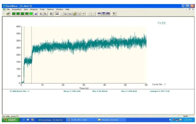
At First Point: The Main cutting force
Figure: 4 At First Point: Fz = 156.3 (N) at N = 325 rpm and f = 0.260 mm/rev
Figure : 4 shows that the online output from the PC based data acquisition System for the measurement of Main Cutting force at First point of double point cutting tool at 325 rpm as speed and 0.260 mm/rev as feed and is recorded.
Figure: 5 Double Point Cutting Tool: First Point: Speed (rpm) Vs Fz (N)
After conducting the Nine experiments the graph is drawn between Speed Vs the Main cutting force for First point for the three different feed rate such as 0.260, 0.238,0.205 mm/rev. Figure : 5 shows the same.
0 50 100 150 200 250
0 100 200 300 400
feed 0.260
feed 0.238
feed 0.205
Speed (rpm)
Fz
(N
)
I. Speed (N):
Case (i)
For the feed 0.205 mm/rev and the speed 135 rpm the main cutting force is recorded as 154.7 N. When the speed is increased to 325 rpm , the main cutting force is decreased and recorded as 120.4 N.
Case (ii)
For the feed 0.238 mm/rev and the speed 135 rpm the main cutting force is recorded as 175.7 N. When the speed is increased to 325, the main cutting force is decreased and recorded as 135.9 N.
Case (iii)
For the feed 0.260 mm/rev and speed 135 rpm the main cutting force is recorded as 212.2 N. When the speed is increased to 325 rpm, the main cutting force is decreased and recorded as 156.3 N.
On observing the above three cases carefully it is noted that as the speed increases, the main cutting force decreases at first point of the double point cutting tool by keeping feed and depth of cut as constants.
At Second Point: The Main cutting force
Figure :6 At Second Point : Fz = 229.4 (N) at N = 325 rpm and f = 0.260 mm/rev
Figure: 6 shows that the online output from the PC based data acquisition System for the measurement of Main Cutting force at Second point of double point cutting tool at 325 rpm as speed and 0.260 mm/rev as feed and is recorded.
Figure : 7 Double Point Cutting Tool : Second Point : Speed (rpm) Vs Fz (N) 0
50 100 150 200 250 300 350
0 100 200 300 400
feed 0.260
feed 0.238
feed 0.205
Speed (rpm)
Fz
(N
)
After conducting the Nine experiments the graph is drawn between Speed Vs the Main cutting force for Second point for the three different feed rate such as 0.260, 0.238,0.205 mm/rev. Figure : 7 shows the same.
I. Speed (N):
Case (i)
For the feed 0.205 mm/rev and the speed 135 rpm the main cutting force is recorded as 245.5 N. When the speed is increased to 325 rpm, the main cutting force is decreased and recorded as 190.1 N.
Case (ii)
For the feed 0.238 mm/rev and the speed 135 rpm the main cutting force is recorded as 269.7 N. When the speed is increased to 325, the main cutting force is decreased and recorded as 229.4 N.
Case (iii)
For the feed 0.260 mm/rev and speed 135 rpm the main cutting force is recorded as 305.6 N. When the speed is increased to 325 rpm, the main cutting force is decreased and recorded as 271.9 N.
With respect to second point also the same trend is noticed. That is as the speed increases, the main cutting force decreases by keeping feed and depth of cut as constants.
At First Point: The Main cutting force
Figure: 8 Double Point cutting tool: First Point: Feed vs. Fz (N)
After conducting the Nine experiments the graph is drawn between Feed Vs the Main cutting force for First point for the three different Speed such as 325,215,135 rpm. Figure : 8 shows the same.
II.Feed (f)
Case (i)
For the speed 135 rpm and the feed 0.205 mm/rev the main cutting force is recorded as 154.7 N. When the feed is increased to 0.260 mm/rev , the main cutting force is increased and recorded as 191.8 N. I.e., the main cutting force is increased by 1.24 times.
Case (ii )
For the speed 215 rpm and the feed 0.205 mm/rev the main cutting force is recorded as 135.3 N. When the feed is increased to 0.260 mm/rev , the main cutting force is increased and recorded as 172.1 N I.e., the main cutting force is increased by 1.27 times.
Case (iii)
0 50 100 150 200 250
0 0.1 0.2 0.3
speed 325
speed 215
speed 135
Feed (mm/rev)
Fz
(N
)
For the speed 325 rpm and the feed 0.205 mm/rev the main cutting force is recorded as 120.4 N. When the feed is increased to 0.260 mm/rev , the main cutting force is increased and recorded as 156.3 N. I.e., the main cutting force is increased by 1.29 times.
On observing the above three cases carefully it is noted that with respect to first point, as the feed increases, the main cutting force also increases by keeping speed and depth of cut as constants.
At Second Point: The Main cutting force
Figure: 9 Double Point cutting tool : Second Point : Feed vs. Fz (N)
II.Feed (f)
Case (i )
For the speed 135 rpm and the feed 0.205 mm/rev the main cutting force is recorded as 224.7 N. When the feed is increased to 0.260 mm/rev , the main cutting force is increased and recorded as 305.6 N I.e., the main cutting force is increased by 1.36 times.
Case (ii )
For the speed 215 rpm and the feed 0.205 mm/rev the main cutting force is recorded as 205.0 N. When the feed is increased to 0.260 mm/rev , the main cutting force is increased and recorded as 287.2 N. I.e., the main cutting force is increased by 1.40 times.
Case (iii)
For the speed 325 rpm and the feed 0.205 mm/rev the main cutting force is recorded as 190.1 N. When the feed is increased to 0.260 mm/rev , the main cutting force is increased and recorded as 271.9 N I.e., the main cutting force is increased by 1.43 times.
On observing the above three cases carefully it is noted that with respect to second point, as the feed increases, the main cutting force also increases by keeping speed and depth of cut as constants.
VII. CONCLUSION
On considering all the discussions for the different speed and feed rate with respect to the main cutting force by keeping the depth of cut as constant the following conclusions are made.
* The performance of the double point cutting tool is quite satisfactory. .
* As the speed increases the main cutting force decreases on the first point and as well as on the second point of the double point cutting tool.
0 50 100 150 200 250 300 350
0 0.1 0.2 0.3
speed 325
speed 215
speed 135
Feed Vs Fz
* As the feed rate increases the main cutting force also increases in proportionate manner on the first point and as well as on the second point of the double point cutting tool.
REFERENCES
[1] D.A. Axinte, W.Belluco, L. De Chiffire “Evaluation of cutting force uncertainty components in turning “ International Journal of Machine Tools and Manufacture 41, 719-730, 2001
[2] Eyup Sabri Topal, Can Cogun “ A cutting force induced error elimination method for turning operations “ Journal of Materials Processing Technology 170, 192-203, 2005
[3] Lalwani D.I., Mehta N.K Jain P.K “ Experimental Investigations of cutting parameters influence on cutting forces and surface Roughness in Finish Hard Turning of MDN250 Steel, Journal of Material Processing Technology 206(1-3), 167-179 2007
[4] Renjith V B, Mathew Babym K R Jayadevan “ Influence of process parameters on cutting forces and Taguchi based prediction of T42-CT HSS single point cutting tool deflection “ 3 (7) 1-6 , 2003
[5] P.G.Benardos, S.Mosialos, G.C.Vosniakos, “ Prediction of workpiece elastic delfection under cutting forces in turning “ Robotics and CIM, 22, 505-514, 2006
[6] Satyanarayana, Kosaraju, Venugopal “ Effect of rake angle and feed rate on cutting forces in an orthoganal turning process “ Int. Conference on trends in mechanical and industrial engineering , Bangkok , Dec , 2011
[7] Sijo M.T and Biju N “ Taguchi method for optimization of cutting parameters in turning operations “ AMAE, 536, 103-105 , 2010
[8] Huang Y and Liang S Y “ Cutting forces modelling considering the effect of tool thermal property –application to CBN hard turning “ Int.J.Mech.Tools Manuf. 43(3), 307-315
[9] Kuzinovski M, Trajcevski N., Cichosz P “ Investigation of cutting forces during machining process by High speed turning “ International scientific conference –serbia , 52-55, 2009
[10] Bala Raju J , Leela Krishna K . Tejomurthy P “ Effect and optimization of machining parameters on cutting force and surface finish in turning of Mild Steel and Aluminum “ International Journal of Research in Engineering and Technology , 2 (11) , 135-141 , 2013
[11] Rodrigues L.L.R., Kantharaj A.N ., Kantharaj B, Freitas W.R.C. and Murthy B.R.N “ Effect of cutting parameters on surface roughness and cutting force in turning Mild Steel, Research Journal of Recent Sciences, 1 (10) 19-26, 2012
[12] Jadhav J.S., Jadhav B.R “ Experimental Study of Effect of cutting parameters on cutting force in turning process” 1(6), 240-248 , 2014
[13]Avdi Salihu, Hakif Zeqiri, Avdyl Bunjaku, Nexhat Qehaja, Azem Kyqyku “ Correlation Research of Cutting Forces during Turning” 14th