Scholarship@Western
Scholarship@Western
Electronic Thesis and Dissertation Repository
11-21-2017 3:00 PM
A 3D US Guidance System for Permanent Breast Seed
A 3D US Guidance System for Permanent Breast Seed
Implantation: Development and Validation
Implantation: Development and Validation
Justin Michael
The University of Western Ontario
Supervisor Fenster, Aaron
The University of Western Ontario
Graduate Program in Biomedical Engineering
A thesis submitted in partial fulfillment of the requirements for the degree in Master of Engineering Science
© Justin Michael 2017
Follow this and additional works at: https://ir.lib.uwo.ca/etd
Part of the Biomedical Devices and Instrumentation Commons
Recommended Citation Recommended Citation
Michael, Justin, "A 3D US Guidance System for Permanent Breast Seed Implantation: Development and Validation" (2017). Electronic Thesis and Dissertation Repository. 5052.
https://ir.lib.uwo.ca/etd/5052
This Dissertation/Thesis is brought to you for free and open access by Scholarship@Western. It has been accepted for inclusion in Electronic Thesis and Dissertation Repository by an authorized administrator of
Permanent breast seed implantation (PBSI) is a promising breast radiotherapy tech-nique that suffers from operator dependence. We propose and have developed an intra-operative 3D ultrasound (US) guidance system for PBSI.
A tracking arm mounted to a 3D US scanner registers a needle template to the image. Images were validated for linear and volumetric accuracy, and image quality in a volunteer. The tracking arm was calibrated, and the 3D image registered to the scanner. Tracked and imaged needle positions were compared to assess accuracy and a patient-specific phantom procedure guided with the system.
Median/mean linear and volumetric error was ±1.1 % and ±4.1 %, respectively, with
clinically suitable volunteer scans. Mean tracking arm error was 0.43 mm and 3D US target registration error ≤0.87 mm. Mean needle tip/trajectory error was 2.46 mm/1.55°.
Modelled mean phantom procedure seed displacement was 2.50 mm. To our knowledge, this is the first reported PBSI phantom procedure with intraoperative 3D image guidance.
Keywords: Ultrasound, 3D Ultrasound, Image Guidance, Brachytherapy, Radiation Therapy, Breast Cancer
A version of chapter 2 has been submitted for publication in Medical Physics as an article titled,“Development of a 3D Ultrasound Guidance System for Permanent Breast Seed Im-plantation” by Justin Michael, Daniel Morton, Deidre Batchelar, Michelle Hilts, Juanita Crook and Aaron Fenster. I designed and performed all experiments, and analyzed all results, and worked with hardware and software developers in the design of the system. Daniel Morton provided assistance in collecting the data for volumetric validation of the 3D US scanner. Deidre Batchelar, Michelle Hilts, and Juanita Crook were involved in the initial conception of a 3D US guidance system for PBSI and were instrumental in translating clinical requirements into technical specifications and features. The guidance system hardware was designed and constructed by Kevin Barker, Jacques Montreuil and Christopher Blake and the software for operation of the guidance system written by Lori Gardi.
Appendix A is a letter-to-the-editor published online in Clinical Oncology on March 31st, 2017 entitled “Reply to: Who Should Bear the Cost of Convenience? A Cost-effectiveness Analysis Comparing External Beam and Brachytherapy Radiotherapy Tech-niques for Early Stage Breast Cancer.” The manuscript was co-authored by Justin Mi-chael, Juanita Crook, Daniel Morton, Deidre Batchelar, Michelle Hilts and Aaron Fenster. I was responsible for conceiving of and drafting the first text of the letter, for conduct-ing the analysis contained within and for submittconduct-ing the letter to the journal, all under the supervision of Dr Aaron Fenster. Juanita Crook was responsible for obtaining data regarding travel distance amongst patients at the Centre for the Southern Interior, in Kelowna, Canada. Juanita Crook, Daniel Morton, Deidre Batchelar and Michelle Hilts each provided editorial input on the final draft.
I would like to thank my supervisor Dr. Aaron Fenster, for his unrelenting support and for giving me the opportunity to grow while wrestling with a challenging and meaningful research project. That opportunity would not have been what it was if it were not for the positive and supporting environment created by all of the members of the Fenster lab, past and present, including Lori Gardi, Kevin Barker, David Tessier, Jacques Montreuil, Igor Gyasckov, Chandima Edirisinghe, Jeff Bax, Jessica Kishimoto, and Tom Hrinivich. Particular thanks goes to Jessica Rodgers and Derek Gillies who’s constant willingness to act as advisors, sounding-boards, and friends has been indispensable in guiding me through my time in graduate school.
Thanks is also due to the many contributors to my research work outside of the Fenster lab, including my advisory committee, Drs. Kathleen Surry and Aaron Ward, for their exceptional tutelage and guidance. Also to our collaborators at the Sindi Ahluwalia Hawkins Centre for the Southern Interior in Kelowna, British Columbia, Juanita Crook, Deidre Batchelar, Michelle Hilts and Daniel Morton, for their guidance and patience (even when I flew across the country only to arrive in Kelowna with a broken scanner).
I would also like to acknowledge the sources of funding who have made this oppor-tunity possible, including the Ontario Institute for Cancer Research and the Ontario Women’s Health Scholar Awards. Their support allowed me to spend my time in gradu-ate school focused on my research rather than my finances, for which I am exceedingly grateful.
Most importantly, I want to thank my friends, family and loved ones. My friends from undergraduate school and high school, too numerous to list, my parents, Vicki Hodgkinson and Kevin Michael, and my amazing partner Katerina Rnic. The importance of their ongoing love and support cannot be overstated.
Contents
Abstract i
Co-Authorship Statement ii
Acknowledgements iii
List of Figures vii
List of Tables x
List of Appendices xi
List of Abbreviations xii
1 Introduction 1
1.1 Early Stage Breast Cancer and its Treatment . . . 1
1.1.1 Breast Cancer and its Progression . . . 1
1.1.2 Treatment of Early Stage Breast Cancer . . . 3
1.1.3 Breast Radiotherapy . . . 5
1.1.4 Radiobiology . . . 5
1.2 Accelerated Partial Breast Irradiation . . . 8
1.2.1 Rationale and Key Concepts . . . 8
1.2.2 Eligibility and Clinical Evidence . . . 10
1.2.3 Interstitial and Intracavitary Breast Brachytherapy . . . 11
1.2.4 External Beam APBI . . . 13
1.2.5 Intraoperative Radiotherapy . . . 13
1.2.6 Emerging Techniques in APBI . . . 14
1.2.7 Permanent Breast Seed Implantation . . . 15
1.3 Challenges of PBSI . . . 18
1.3.1 Operator Dependence and Previous Work . . . 18
1.3.3 Imaging Dissimilarities Between Planning and Guidance . . . 20
1.4 Thesis Objective . . . 22
1.5 Relevant Physics: Brachytherapy and 3D Ultrasound . . . 22
1.5.1 Brachytherapy Physics . . . 22
1.5.2 Three-Dimensional Ultrasound Physics . . . 23
1.6 Ultrasound Guidance of Brachytherapy Procedures . . . 25
1.6.1 Three-Dimensional US Guidance of Prostate, HDR Breast Bra-chytherapy . . . 25
1.6.2 Other Methods of Needle and Needle Template Tracking and Guid-ance . . . 25
References 26 2 System Development and Validation 38 2.1 Introduction . . . 38
2.2 Materials and Methods . . . 40
2.2.1 System Design . . . 40
2.2.1.1 Three-Dimensional US Scanner . . . 40
2.2.1.2 Encoded Arm and Modified Needle Template . . . 41
2.2.2 System Calibration and Validation . . . 43
2.2.2.1 Three-Dimensional Image Reconstruction . . . 43
2.2.2.2 Encoder Mapping . . . 45
2.2.2.3 Tracking Arm Point Accuracy . . . 47
2.2.2.4 Image to Scanner Registration . . . 48
2.2.2.5 Template Localization Accuracy . . . 49
2.2.2.6 Needle Insertion Accuracy . . . 49
2.2.2.7 Phantom Procedure . . . 51
2.2.2.8 Statistical Methods . . . 53
2.3 Results . . . 53
2.3.1 Three-Dimensional Image Reconstruction . . . 53
2.3.2 Encoder Mapping . . . 55
2.3.3 Tracking Arm Point Accuracy . . . 55
2.3.4 Image to Scanner Registration . . . 58
2.3.5 Template Localization Accuracy . . . 59
2.3.6 Needle Insertion Accuracy . . . 59
2.4 Discussion . . . 62
2.4.1 Three-Dimensional Image Reconstruction . . . 62
2.4.2 Encoder Mapping . . . 63
2.4.3 Tracking Arm Point Accuracy . . . 63
2.4.4 Image to Scanner Registration . . . 64
2.4.5 Template Localization Accuracy . . . 64
2.4.6 Needle Insertion Accuracy . . . 64
2.4.7 Phantom Procedure . . . 65
2.5 Conclusions . . . 66
References 66 3 Conclusions and Future Work 72 3.1 Overview and Research Questions . . . 72
3.2 Summary and Conclusions . . . 72
3.3 Limitations . . . 75
3.4 Future Work . . . 76
3.4.1 Device Refinements . . . 76
3.4.1.1 Hardware Refinements . . . 76
3.4.1.2 Software Refinements . . . 78
3.4.2 Clinical Translation . . . 79
References 80
Appendices 84
A Letter to the Editor 84
B 94km Map - Methods 87
C Ethics Approval 91
D Permission for Reproduction of Scientific Articles 92
Curriculum Vitae 93
List of Figures
1.1 Summary of the stages of cancer progression. Adapted from Canadian Partnership Against Cancer, 2015 [3] . . . 2 1.2 Illustration of the geographic areas of Canada within 93.6 km travel
dis-tance of a Canadian Cancer Centre. For Canadian patients living outside of the areas highlighted in red (estimated 15% of the Canadian popula-tion), our analysis revealed that PBSI is less costly than standard radio-therapy. Available online as an interactive map: http://bit.ly/94kmMap 17
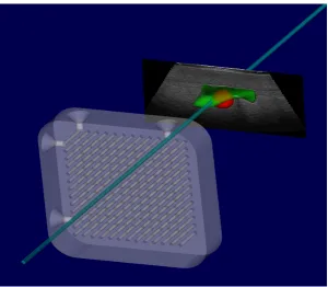
2.1 Screenshot from guidance software showing registered needle template re-lative to central slice of 3D US image and segmented seroma phantom (green). Teal cylinder indicates projection of selected needle template position. . . 42 2.2 a) Image of guidance system positioned above commercial breast phantom.
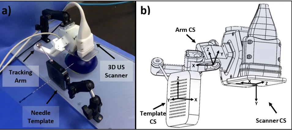
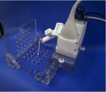
b) Illustration of coordinate systems (CSs) used in validation (‘Image’ CS not shown). . . 43 2.3 Summary of information pipeline in the guidance system and the list of
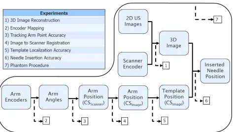
experiments used in validation. Experiments 1–6 validate a step in the process indicated by dashed arrows. Experiment 7 evaluates the process as a whole. CS = coordinate system. . . 44 2.4 Encoder mapping set-up. a) Surface plate, gauge blocks and height stand
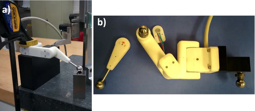
in use during calibration of the most distal joint. b) Partially disassembled template tracking arm with tooling balls. The most distal segment (left) has been removed and a tooling ball added in its place. A machined extension and tooling ball (right) has been added. . . 46 2.5 Guidance system positioned in tracking arm calibration jig. Jig contained
45 fiducial divots arranged in a 9×5 grid pattern separated by 2 cm in
each direction. Mounting position of scanner adjusted forward/back and left/right in 3 cm increments, so that 180 (45×4) known positions are
available for calibration/validation. . . 47
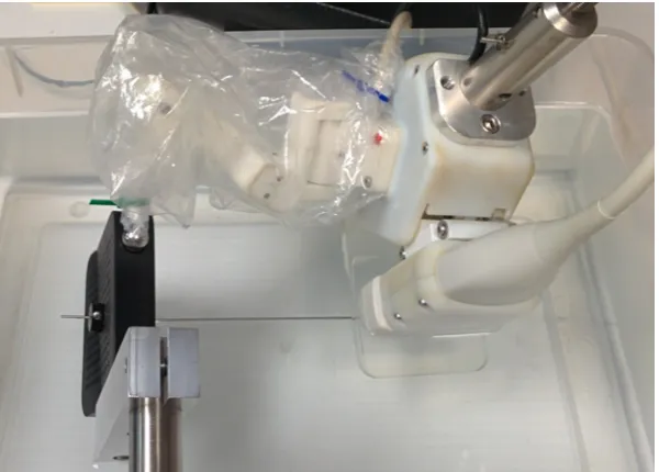
collar affixed to the needle allows for a known insertion depth into a bath of isopropyl alcohol and water. Comparison of needle position in tracking and imaging quantifies tracking accuracy. Tracking arm has been bagged to prevent damage if immersed. . . 50
2.7 Screenshot showing visual overlay of planned needle position (purple) and projected needle trajectory (cyan) on live 2D US image for guidance during needle insertion. Inserted needle is visible in US image beneath purple overlay. . . 52
2.8 Results of linear measurement validation using a 3D grid phantom im-mersed in 7.25 % by volume isopropyl alcohol solution. Columns and error bars show medians and 95 % confidence intervals, respectively. N=40 per direction, per depth setting. . . 54
2.9 Multi-planar views of a 3D US image captured from a healthy volunteer using developed system. Left: View showing representative slices of image along orthogonal planes. Arrows and labels indicate principal axes. Right: View illustrating geometry of reconstructed scans. Field of view visible in axial-elevational plane is constant across lateral axis. . . 55
2.10 Integral error of each encoder in the tracking arm as a function of absolute position when calibrated. Each encoder was calibrated using multiple mounting positions in order to span the full range of motion. Dashed black line indicates the estimated integral encoder error after smoothing. All plots show integral error over 360° range (0–4095 encoder counts). . . 56
2.11 Normalized histogram of target registration error (TRE) observed dur-ing trackdur-ing arm validation plotted with respect to probability (N=240). Dashed black line indicates mean TRE (0.43 mm). . . 57
2.12 95 % prediction ellipsoid of arm validation error plotted with respect to the arm coordinate system (units: mm). Black dots indicate individual point measurement errors and red lines indicate boundaries of 95 % confidence ellipsoids. Gray dots and adjacent ellipses indicate projections of the above onto canonical planes. See Figure 2.2b for coordinate system description. 58
with respect to the image coordinate system. Black dots indicate in-dividual point measurement errors and red lines indicate boundaries of 95 % confidence ellipsoids. Gray dots and adjacent red ellipsoids indic-ate projections of the above onto canonical planes. See Figure 2.2b for coordinate system description. . . 61 2.14 Post-operative images of phantom procedure. a) Visualization of planned
and observed needle positions overlaid on post-op micro-CT. Planned seed-bearing (fiducial) needles shown in blue (cyan) with observed needles shown in red (pink). Pre-op seroma following registeration to post-op micro-CT shown in green. b) Reconstucted plane of 3D US with seroma and all 15 needles visible. . . 62
List of Tables
1.1 Simplified table of stage by TNM classification. Adapted from American Joint Committee on Cancer, 2009 [5]. Note that stages appear to overlap in individual categories (T/N/M) only because stage is dependent on all categories (e.g. T2N1M0 is stage 1 while T2N2M0 is stage 2). Tis = tumour - carcinoma in situ; N1mi = N1 micromestasis) . . . 2 1.2 Summary of completed and ongoing phase III prospective randomized
clinical trials comparing APBI to WBI. Adapted from Tann et al. 2016 [44] with the addition of recently published results from Coles et al. 2017 [48] on the IMPORT-LOW trial. . . 12
2.1 Results of volumetric validation comparing segmented volume in 3D US to water displacement volume. 95 % confidence intervals calculated using a Welch ’s t-test. . . 54 2.2 Confidence intervals on the mean error in each axis following tracking arm
point accuracy validation. Error evaluated in the arm coordinate system (Figure 2.2b). . . 57 2.3 Target and fiducial registration error (TRE and FRE) of registering the
scanner and image coordinate systems using a phantom with 12 string intersections (6 fiducials, 6 targets). . . 59 2.4 Mean (SD) of components of template localization errors. Rotations and
translations expressed with respect to the scanner coordinate system (Fig-ure 2.2b). Positive angles indicate clock-wise rotation about an axis when viewed from the origin. . . 59 2.5 Magnitude of needle tip and trajectory error when comparing expected
needle position from tracking and insertion depth to observed needle po-sition in 3D US. . . 60 2.6 Confidence intervals on the mean error in each axis following needle
in-sertion accuracy validation. Error evaluated in the imaging coordinate system (Figure 2.2b) and averaged across all needle insertion depths. . . 61
List of Appendices
Appendix A Letter to the Editor . . . 84
Appendix B 94km Map - Methods . . . 87
Appendix C Ethics Approval . . . 91
Appendix D Permission for Reproduction of Scientific Articles . . . 92
List of Abbreviations
125I Iodine-125
103Pd Palladium-103
192I Iridium-192
2D Two-Dimensional 3D Three-Dimensional
3D-CRT 3D Conformal Radiotherapy
APBI Accelerated Partial Breast Irradiation API Application Programming Interface BCS Breast Conserving Surgery
BCT Breast Conserving Therapy BED Biologically Effective Dose CAD Canadian Dollars
CRA Canada Revenue Agency CS Coordinate System
CSI Centre for the Southern Interior CT X-ray Computed Tomography CTV Clinical Target Volume
DNA Deoxyribonucleic Acid DoF Degree of Freedom
EBRT External Beam Radiotherapy EM Electromagnetic
ER Estrogen Receptor-α
ESCD Estimated Study Completion Date FLE Fiducial Localisation Error
FRE Fiducial Registration Error
GADM Database of Global Administrative Areas
GEC-ESTRO Groupe Européen de
Curiethérapie-European Society for Therapeutic Radiology and Oncology
GPS Global Positioning System GTV Gross Tumour Volume HDR High Dose-Rate
HER2 Human Epidermal Growth Factor Receptor 2 HR Hormone Receptor
ICB Intracavitary Brachytherapy ICP Iterative Closest Point
IMRT Intensity Modulated Radiotherapy IORT Intraoperative Radiotherapy JSON JavaScript Object Notation KML Keyhole Markup Language kVp Kilo-Voltage Peak
LDR Low Dose-Rate
linac Linear Particle Accelerator LQ Linear-Quadratic
MDR Medium Dose-Rate
MIB Multicatheter Interstitial Brachytherapy ML Multi-Lumen
MLC Multi-Leaf Collimator MR Magnetic Resonance
MRI Magnetic Resonance Imaging NIBB Non-Invasive Breast Brachytherapy OAR Organ-at-Risk
PBSI Permanent Breast Seed Implantation PC Personal Computer
PgR Progesterone Receptor PTV Planning Target Volume RCT Randomized Clinical Trial RMSE Root Mean Squared Error
SAVI Strut Adjusted Volume Implant SBRT Stereotactic Body Radiation Therapy SD Standard Deviation
SERM Selective Estrogen Receptor Modulator Tactual Actual (Ground Truth) Transform
Terror Error Transform
TG43 American Association
of Physicists in Medicine Task Group 43 Tmeasured Measured Transform
TNM Tumour-Node-Metastasis TPX Polymethylpentene Plastic TRE Target Registration Error TRUS Transrectal Ultrasound US Ultrasound
USB Universal Serial Bus WBI Whole Breast Irradiation
Chapter 1
Introduction
1.1 Early Stage Breast Cancer and its Treatment
1.1.1 Breast Cancer and its Progression
For Canadian women, breast cancer is the most commonly diagnosed cancer and the second highest cause of cancer related death, with an estimated 26,300 new cases and 5,000 deaths in 2017 [1]. Globally, breast cancer is the 2nd most common cancer and the 5th highest cause of cancer death, with an estimated 1.7 million cases and 522,000 deaths in 2012 [2].
Like all cancers, if left untreated breast cancer follows a progression from a localized group of abnormal cells to larger invasive tumours that spread (metastasize) to other parts of the body via the lymph nodes and circulatory system. The extent of progression is categorized by stage from 0–4, as summarized in Figure 1.1. Assessment of cancer stage acts as a strong indicator of prognosis, influencing the choice of treatment for each patient.
Cancer stages are defined using the Tumour-Node-Metastasis (TNM) system, which provides criteria to score the cancer’s progression with respect to the size of the original tumour, any spread to nearby lymph nodes, and the presence or absence of distant metastases. Each item on the TNM scale is given a numeric rating (T:0-4,N:0-3, M:0-1), sometimes with additional sub-specification (e.g. Tis for carcinoma in situ), and the aggregation of the three scores is used to define the cancer stage. A simplified version of the definition of cancer stage by TNM category is shown in Table 1.1. The term “early-stage” breast cancer generally refers to stages 0–2 [4].
While knowledge of cancer stage is useful for prognosis and treatment selection, the definition of stage is primarily anatomic, despite a growing number of non-anatomic biomarkers [6]. Of those non-anatomic biomarkers, three are routinely assessed clinically
Figure 1.1: Summary of the stages of cancer progression. Adapted from Canadian Part-nership Against Cancer, 2015 [3]
Table 1.1: Simplified table of stage by TNM classification. Adapted from American Joint Committee on Cancer, 2009 [5]. Note that stages appear to overlap in individual categories (T/N/M) only because stage is dependent on all categories (e.g. T2N1M0 is stage 1 while T2N2M0 is stage 2). Tis = tumour - carcinoma in situ; N1mi = N1 micromestasis)
Stage T N M
in breast cancer: the expression of two hormone receptors, estrogen receptor-α(ER) and progresterone receptor (PgR), and the presence of HER2 (human epidermal growth factor receptor 2) [7]. All three of these biomarkers indicate a variable by which the cancer cells can be differentiated from healthy cells, making it possible to supplement treatment with targeted therapies. ER and PgR status, referred to as ER or PgR positive respectively, are indicative of tumour cells whose growth is dependent on estrogen, making it possible to target these cells using drugs that either disrupt the interaction of estrogen with these receptors, selective estrogen receptor modulators (SERMs) such as tamoxifen, or that suppress the production of estrogen, such as aromatase inhibitors. Approximately 75% of invasive breast cancers are ER positive and 60–70 % are PgR positive [7], with hormone receptor (HR) positive tumours having a generally favorable prognosis relative to HR negative tumours [8]. The third biomarker, HER2, is a proto-oncogene (precursor to a gene that can cause cancer) that is amplified in 20–30 % of invasive breast cancers [9]. HER2 positive tumours can be targeted with an antibody based treatment called trastuzumab (trade name Herceptin), which is considered an integral part of therapy for patients with HER2 positive tumours [9].
In addition to tumour specific biomarkers, genetic risk factors for breast cancer have also been identified, most notably mutations in the BRCA1 and BRCA2 genes. These genes are both involved in a key pathway for the repair of DNA damage (homologous recombination repair) and cells with mutations in these genes must rely on a secondary pathway (non-homologous end joining) that is more error-prone [10]. The reliance on an error-prone repair pathway leads to more frequent mutation and a greater risk of tumour development, with an estimated lifetime breast cancer risk of >80% [11]. Despite the exceedingly high breast cancer incidence amongst women with BRCA1/2 mutations, evidence on their value as a prognostic indicator remains unclear [12].
1.1.2 Treatment of Early Stage Breast Cancer
Techniques for breast cancer treatment can be summarized into three categories: surgical, systemic, and radiation therapies.
examine the extent of normal tissue clearance around the excised tumour. The extent of normal tissue around the excised tumour, is referred to as the excision ‘margins’. ‘Positive margins’ indicate that the tumour comes to the edge of the excised volume, likely indicating that not all of the tumour was removed, making it an indication for re-excision [14]. An excised tumour may also be considered to have ‘close margins’ if the amount of normal tissue around the tumour is less than a prespecified safety margin, typically on the order of 1–5 mm [14]. While close margins may indicate further treatment, such as re-excision, consensus guidelines published in 2013 indicate that more widely clear margins do no decrease the rate of ipsilateral recurrence [14].
Breast conserving therapy was introduced as an alternative to mastectomy [15], or the surgical removal of the entire affected breast, in order to achieve a better cosmetic outcome while still addressing the disease. Although the effectiveness of BCT has been established, mastectomy is still necessary for certain patients such as those with multi-centric disease (i.e. multiple tumours in the same breast), patients for whom a lumpec-tomy has failed to achieve negative margins, or for locally recurrent cases [16].
Systemic therapies refer to treatments that travel through the blood stream, reaching cells throughout the body. While early-stage cancers are, by definition, localized to the breast, it is generally accepted that a portion of patients with disease that is localized by clinical standards will have micro-metastases that are not presently detectable. The risk of micro-metastases motivates the exploration of systemic therapies in combination with surgical and/or radiotherapeutic treatments, even for early-stage disease [17]. Cytotoxic chemotherapy is one form of systemic therapy which uses drugs that preferentially target rapidly dividing cells, typically administered in a combination therapy of multiple drugs [18]. A review of international guidelines suggested that chemotherapy is indicated for patients with tumours >1 cm or with nodal involvement [19].
In addition to the traditional chemotherapeutic forms of systemic therapy, targeted therapies for the cancer subtypes discussed in section 1.1.1 above, namely SERMS or aromatase inhibitors for ER and/or PgR positive tumours and trastuzumab for HER2 positive tumours, are typically indicated when the appropriate subtype has been identi-fied.
1.1.3 Breast Radiotherapy
The delivery of breast radiotherapy may use one of two classes of techniques: ex-ternal beam radiotherapy (EBRT) and brachytherapy, with EBRT currently being by far the most common. In EBRT, a linear particle accelerator (linac) is used to generate a beam of ionizing radiation that is directed towards the patient. The beam is shaped or modulated using secondary collimation such as jaws or multi-leaf collimators (MLC’s) in combination with step-and-shoot or arc delivery techniques [21]. EBRT may deliver photons or electrons, depending on the device used to produce them and its configuration, with energies typically ranging from 4–20 MeV [21].
Conversely, brachytherapy uses a sealed source, such as a radioactive seed or wire, placed in or near the target, such as inside a tumour or at the surface of a superficial lesion. The prefix ‘brachy’ comes from the Greek word for ‘short’, reflecting the short distance between the source and the target. The “sealed” source of brachytherapy contrasts with the use of systemic radiotherapy, in which radioactive compounds enter the bloodstream, such as orally administered iodine-131 to treat thyroid cancer [22].
Brachytherapy may be further categorized by the rate at which dose is delivered. Low, medium, and high dose rate (LDR, MDR, and HDR, respectively) brachytherapy is defined as dose rates from 0.2–0.4 Gy/h, 2–12 Gy/h and >12 Gy/h, respectively [23].
Brachytherapy radiation may also be delivered intermittently, known as pulsed dose rate [23], although in modern practice LDR and HDR brachytherapy are most common.
While LDR brachytherapy can be delivered by manually placing sources, HDR bra-chytherapy is potentially dangerous to the operator and is delivered automatically and remotely using a device called an afterloader. An afterloader is an electronic device that uses motors and sensors to sequentially move a single radioactive source attached to the end of a wire through multiple catheters implanted in or placed near the target. The dose is adjusted based on where the source is moved (dwell positions) and how long it stays there (dwell times). Dwell times and positions are specified in a treatment plan determined based on target geometry determined from imaging of the area [24]. Treat-ment times are in the range of minutes, and are delivered in discrete ‘fractions’, similar to the EBRT approach. Energies of commonly used brachytherapy sources range from 21–1250 keV [23].
1.1.4 Radiobiology
one or both strands of the double-helix, known as single- and double-stranded breaks, respectively. Double stranded breaks are thought to be the most important DNA lesions for radiotherapy as they are principally responsible for cell killing [10]. While ionizing radiation causes damage to healthy cells, it is especially damaging to cancerous cells [25], creating a differential response that allows radiation to be used for treatment. The magnitude of the difference in response between cancerous and non-cancerous cells can be described in terms of the therapeutic ratio, also known as the therapeutic index, which is defined as the ratio of the tumour control probability to the normal-tissue complication probability for a fixed level of normal tissue damage [10].
As a result of the effect of ionizing radiation on both cancerous and healthy cells, radiotherapy is often accompanied by adverse events. These side-effects are caused by either radiation damage to the surrounding healthy tissue of the target organ or to other nearby organs, termed organs-at-risk (OARs). In the case of breast radiotherapy, OARs include the heart, lungs, skin, ribs and contralateral breast [26]. Adverse events of the skin can include erythema (redness), moist desquamation, telangiectasia, and induration [27], while other organ adverse events include cardiomyopathy and secondary cancers [28].
The biological effects of radiotherapy are characterized principally by the dose de-livered to tissues measured in Gray (Gy), where 1 Gy corresponds to 1 joule of absorbed energy from ionizing radiation per kilogram of matter [29]. The dose delivered during radiotherapy is calculated using simulations based on the geometry of the target (e.g. tumour) relative to the source, and established calibration data describing the dose dis-tribution. In the case of EBRT, the dose distribution is a function of penetration depth, and in the case of brachytherapy it is a function of distance and angle from the source. The attenuation of dose as it travels through a medium (e.g. tissue) depends on the beam characteristics, with lower energy photons attenuated more rapidly, but generally reach a maximum at or near the entry point of the beam, for EBRT, or adjacent to the source, for brachytherapy, and decay to zero with increasing depth.
repair mechanisms, making reassortment a mechanism of sensitizing cells that might have been radioresistant during a previous fraction. Repopulation refers to the regrowth of cell populations, healthy or cancerous, to replace cells killed by radiation therapy. Reoxygen-ation refers to the return of oxygen supply to tumour cells to maximize its radiosensitizing effects in catalyzing the permanent damage of DNA by free radicals. Repair refers to the ability of cells to repair sublethal damage to their DNA. Lastly, radiosensitivity refers to intrinsic differences in the radiosensitivity of different cell types. The historical rationale for fractionated therapy is that it leverages the repair and repopulation of healthy cells to minimize toxicity, while allowing reoxygenation and reassortment to radiosensitize cancerous cells [10].
The relationship between the dose of the fraction delivered and its effect on cell killing has been studied extensively, resulting in the linear-quadratic (LQ) model. In the LQ model, the effect of radiation damage on cell survival is modelled as the sum of two components, one linear with respect to dose (α), and the other quadratic (β), summarized in equation 1.1:
S =eαD+βD2 (1.1) whereS is the surviving fraction of cells, Dis the radiation dose andαandβare constants representing properties of a given tissue type. In this model, the linear component is thought to represent the effect of directly lethal damage to the cells while the quadratic component is though to represent cell–death due to accumulation of sub-lethal damage. The LQ model allows for dosage in different fractionation schemes to be calculated such that they result in the same survival fraction, a concept referred to as biologically effective dose (BED) [10]. As a result, prescribed dose in a regimen with greater fractionation tends to be higher in order to achieve the same BED.
Additionally, BED is dependent on the values of α and β, specifically on the ratio of α/β, which vary with different tissues. Cancerous tissue tends to have a higher value of α/β than late responding normal tissue, such that the reduction in BED due to frac-tionation is greater for healthy tissues than cancerous tissues. As a result, fracfrac-tionation generally allows for the therapeutic ratio to be increased by raising the BED delivered to cancerous tissue while keeping the BED of late responding healthy tissues constant. Traditionally the values of α/β used in BED calculations were taken as 3 Gy for late responding normal tissues and 10 Gy for cancerous tissues [31].
number of fractions separated by an infinitely small period of time. However, application of the usual equations for BED to permanent seed brachytherapy is complicated by the decaying dose rate over time and by the violation of the usual assumption that time between fractions is sufficient for all sub-lethal radiation damage to be repaired.
While traditional calculations for BED have used the values of 3 Gy and 10 Gy to represent α/β of all cancerous and late responding normal tissues, respectively, recent research has explored breast cancer specific values of α/β. Analysis of data from a phase III randomized clinical trial comparing different fractionation schedules of whole breast irradiation following lumpectomy showed that the difference inα/β between healthy and cancerous tissue in this context may be much smaller than previously thought. Estimated
α/β for local-regional relapse was 4.6 Gy (95% CI 1.1–8.1 Gy) and for changes in breast appearance was 3.4 Gy (95% CI 2.3–4.5 Gy) [32]. This evidence suggests that the dif-ference in α/β between cancerous and healthy tissue in breast cancer may be smaller than previously thought, or possibly even reversed. A relatively low value of α/β in breast cancer would support the use of hypofractionation, although the available data is not yet conclusive. Despite the clear implications of α/β for fractionated radiotherapy, radiobiological models for comparing fractionated regimens to continuous, low dose rate radiotherapy (i.e. permanent seed brachytherapy) depend on the recovery rate of sub-lethal damage but are relatively independent of α/β [33]. Thus, the implications of the emerging research on α/β of cancerous and healthy breast tissue for permanent seed breast brachytherapy (discussed below) are unclear.
1.2 Accelerated Partial Breast Irradiation
1.2.1 Rationale and Key Concepts
In the years of clinical follow-up on the treatment of early-stage breast cancer with BCT, a pattern was observed in which recurrences were more likely to occur at the site of the originally treated tumour [13]. Research investigating the addition of a targeted boost of radiation to the tumour bed in addition to WBI showed improvements in ipsilateral recurrence [34], supporting targeted irradiation as a strategy to improve therapy.
If increased dose to high-risk regions could improve effectiveness, could reduced dose to low-risk regions reduce treatment burden? Such was the motivation for accelerated partial breast irradiation (APBI), the delivery of radiation to only a portion of the breast surrounding the original tumour site at an accelerated rate.
five days a week for five weeks. The addition of a targeted boost can extend the total treatment time to 6–7 weeks [34]. While more recent clinical trials have shown equivalent tumour control when whole breast irradiation is shortened to 40 Gy over 15 fractions (2.67 Gy each) [35], this 3–week radiation schedule remains burdensome.
The treatment burden is hypothesized to cause some women to choose mastectomy instead of BCT or even decline radiotherapy and accept an increased risk of recurrence, with evidence for that hypothesis reflected in both anecdotal [36] and statistical accounts [13]. Anecdotally, there is the account of a Venezuelan woman treated using interstitial brachytherapy at the Oschner Clinic in New Orleans, USA, the first APBI patient in the modern era, for whom there were no linear accelerators in her home country within 8 hours of her home [36]. Statistically, BCT is often underutilized, with the proportion of eligible patients who undergo BCT estimated between 35–80 % and the proportion of patients who receive BCS but forego radiation therapy estimated between 15–30 % [13]. The lengthy duration of radiation treatment is widely thought to contribute to this underutilization [37]. Additionally, several factors that increase the burden of an extended treatment; including distance to treatment, ambulatory status and rural populations; correlate with underutilization of BCT [13]. As a result, APBI is hypothesized to of-fer a tool to increase the utilization of BCT by eligible patients in addition to reducing the treatment burden of those who would have received radiation therapy regardless of treatment length.
Writing against this hypothesis, Yao & Recht [38] found that the increased use of APBI brachytherapy amongst breast cancer patients in the United States from 0.2–3.1 % between 2000–2008 did not correspond to a reduction in the proportion of patients who did not receive radiotherapy. They conclude that the removal of “institutional, logistical and financial barriers” may be more promising avenues to reduce noncompliance [38]. Despite having data from over 300,000 patients, the authors lack data on the proportion of patients for whom APBI brachytherapy was available or their characteristics, nor on any control group that might account for other influences on treatment patterns. As a result, their attribution of a lack of reduction in non-compliance to a failed promise of APBI brachytherapy is largely without evidence.
The observation of the local nature of tumour control and recurrence as well as the significance of treatment burden on breast cancer patients, led to the rise of accelerated partial breast irradiation (APBI) as an active area of research. It was hypothesized that APBI could maintain tumour control with rates of adverse effects held constant or improved while accelerating the treatment and reducing the burden to the patient.
consistent with radiation therapy planning more broadly. In radiotherapy planning, gross tumour volume (GTV) refers to any visible tumour volume under imaging or clinical exam, while the clinical target volume (CTV) includes the GTV as well as subclinical disease not visible under imaging. The CTV thus defines the volume of tissue that is clinically relevant for treatment. The planning target volume (PTV) represents an expansion to the CTV to account for any inaccuracies in set-up or delivery [39]. In the context of APBI more specifically, treatment is generally delivered to the surgical cavity (seroma) following lumpectomy rather than to the tumour itself. Thus, GTV is not generally defined, while borders of the CTV and PTV are determined by expanding contours of the seroma; the fluid-filled cavity left behind from surgery.
1.2.2 Eligibility and Clinical Evidence
With the primary motivations for using APBI over WBI related to improving second-ary treatment considerations, such as adverse effects and treatment burden, rather than the primary consideration of tumour control, inclusion criteria are limited to patients for whom tumour control from established therapy is already very good. Task groups representing national or international bodies have published recommendations for APBI eligibility criteria, including the American Brachytherapy Society [40], the American So-ciety for Radiation Oncology [41], the American SoSo-ciety of Breast Surgeons [42], and the Groupe Européen de Curiethérapie-European Society for Therapeutic Radiology and Oncology (GEC-ESTRO) [43]. Additionally, many large-scale clinical trials (discussed below) have defined their own criteria. Despite variation between recommendations, most contain a minimum age (>45–60), a maximum tumour size (<2–3 cm), tumour margin requirements (negative margin>0–2 mm) and little to no lymph-node involvement (≤0–3
nodes). Eligibility recommendations of the task groups mentioned above are summarized by Tann et al. [44] and those used by various phase III clinical trials are described in the citations and clinical trial registry numbers given in Table 1.2.
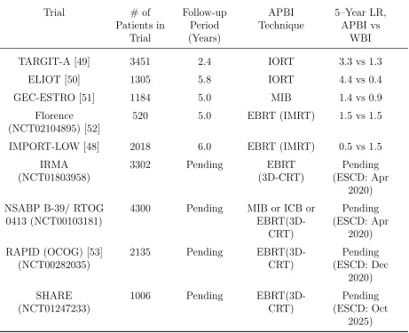
The most robust source of evidence for the clinical efficacy of APBI is derived from five phase III randomized clinical trials (RCTs) comparing ipsilateral breast tumour re-currence following APBI and WBI. The results of these studies and the techniques of APBI they evaluated are given in Table 1.2, alongside descriptions of four ongoing phase III RCTs and their expected study completion dates (ESCD). Five–year recurrence rates in the control arms of the phase III RCTs published to date have all been ≤1.5%,
were statistically significantly different from their control arms. Of the remaining two trials, ELIOT and TARGIT-A, both were delivered with intraoperative radiotherapy (IORT). Recurrence rates in the ELIOT trial were worse than the treatment arm (4.4 % vs 0.4 %, p<0.0001) while differences in recurrence rates of the TARGIT-A trial (3.3 % treatment vs 1.3 % control) had a p-value of 0.04. However, recurrence rate differences in TARGIT-A were deemed not significantly different by the study’s authors due to a pre-defined significance level of 0.01 to reflect multiple comparisons [45]. The study’s au-thors concluded the results demonstrated non-inferiority, although interpretation of the trial was met with considerable controversy when it was published (discussed in section 1.2.5 below).
Two recent reviews of the clinical efficacy of APBI reached contradictory conclusions, with one excluding IORT trials and concluding that the efficacy of APBI relative to WBI was supported [46], while the other included IORT trials and concluding the opposite [47]. Both reviews were written prior to the publication of the IMPORT-LOW trial, which provided additional evidence supporting APBI.
In summary, with the possible exception of IORT based approaches, data available from multiple large RCT’s supports the use of APBI for well-selected patients, with results from other RCT’s comprising an additional 10,000 patients pending in the coming years.
1.2.3 Interstitial and Intracavitary Breast Brachytherapy
The first modern treatment of APBI was delivered using interstitial breast brachy-therapy [36], in which 15–25 needles are inserted into the breast and exchanged for flexible catheters [54]. With the catheters implanted, an afterloader is used to deliver HDR brachytherapy over the following week based on a treatment plan developed using CT. Treatment is typically fractionated over five days, after which the catheters are removed. LDR brachytherapy has been delivered using iodine-125 (125I) or iridium-192
(192I) but the most common source configuration is HDR192I [55].
Despite initial success with interstitial brachytherapy, the technique was not widely adopted. Planning and delivering the procedure is time-consuming and requires a spe-cialized skill set [37], and with limited availability of adequate training, adoption was largely limited to high-volume centres [13].
Table 1.2: Summary of completed and ongoing phase III prospective randomized clinical trials comparing APBI to WBI. Adapted from Tann et al. 2016 [44] with the addition of recently published results from Coles et al. 2017 [48] on the IMPORT-LOW trial.
Trial # of Patients in
Trial
Follow-up Period (Years)
APBI
Technique 5–Year LR,APBI vs WBI
TARGIT-A [49] 3451 2.4 IORT 3.3 vs 1.3 ELIOT [50] 1305 5.8 IORT 4.4 vs 0.4 GEC-ESTRO [51] 1184 5.0 MIB 1.4 vs 0.9
Florence
(NCT02104895) [52] 520 5.0 EBRT (IMRT) 1.5 vs 1.5 IMPORT-LOW [48] 2018 6.0 EBRT (IMRT) 0.5 vs 1.5
IRMA
(NCT01803958) 3302 Pending (3D-CRT)EBRT (ESCD: AprPending 2020) NSABP B-39/ RTOG
0413 (NCT00103181) 4300 Pending MIB or ICB or EBRT(3D-CRT)
Pending (ESCD: Apr
2020) RAPID (OCOG) [53]
(NCT00282035) 2135 Pending EBRT(3D-CRT) (ESCD: DecPending 2020) SHARE
(NCT01247233) 1006 Pending EBRT(3D-CRT) (ESCD: OctPending 2025)
first intracavitary device developed was the MammoSite applicator, approved by the FDA in 2002 [13], which contained a single centrally positioned lumen inside of a spher-ical balloon. The symmetrspher-ically shaped applicator and single lumen mean the device is unable to deliver asymmetrical dose distributions and adequate conformance to the seroma may be problematic [13]. Newer, multi-lumen devices such as the MammoSite ML (multi-lumen) and the Contura balloon applicator, as well as the non-balloon based strut adjusted volume implant (SAVI) device, have since been developed to offer greater dosimetric flexibility, including the delivery of asymmetrical plans. As of 2017, Hologic, the makers of MammoSite ML and the Contura device, claim that over 90,000 women in the United States have received intracavitary APBI using their devices [56].
1.2.4 External Beam APBI
In addition to brachytherapy approaches to APBI, several techniques also exist us-ing EBRT, principally 3D conformal radiotherapy (3D CRT) and intensity-modulated radiotherapy (IMRT). In 3D CRT, MLCs are used to modify the shape of the beams to conform to the outline of the PTV in the ‘beams-eye view,’ reducing the dose delivered to healthy tissue. Conversely, IMRT modifies both the shape and intensity of the beams, using the motion of the MLC leaves to modify the dose across the beam by leaving some portions of the field open for more time than others.
In completed and ongoing phase III clinical trials of APBI that incorporated an external beam arm, dose fractionation schemes range from 30–40 Gy to the PTV in 5–15 fractions [44]. The most common fractionation scheme, used in the three largest phase III clinical trials of EBRT, is 38.5 Gy in 10 fractions delivered over 5–10 days. A simulation-based dosimetric analysis of organs at risk during APBI suggested that EBRT-APBI techniques deliver less dose to OARs than WBI or MIB [28].
1.2.5 Intraoperative Radiotherapy
patients, with IORT serving as a radiation boost to the tumour bed [45].
There are two published phase III RCT’s incorporating IORT, the ELIOT trial and the TARGIT-A trial, both of which are discussed in Table 1.2. ELIOT compared electron based IORT to WBI in an equivalence design and found that electron based IORT had significantly higher rates of recurrence (4.4% vs 0.4 %, hazard ratio 9.3) [50]. Despite these rates being within a prespecified equivalence margin (7.5%) [50], the results were viewed as disappointing [57] and the increased recurrence attributed to patient selection [50, 57].
Conversely, TARGIT-A used photon based IORT and stratified sampling into pre- and post- histology groups. The pre-histology group was randomized prior to lumpectomy and used the risk-adapted approach described above, while the post-histology group was randomized after histology was available and IORT performed by reopening the surgical cavity. The TARGIT-A trial found 5–year local recurrence rates for TARGIT and EBRT of 3.3 % and 1.3 %, respectively (p = 0.04), considered not statistically significant due to a pre-specified significance level of 0.01 to account for repeated tests due to an interim analysis published in 2010 [58]. The authors concluded that recurrence was within a pre-specified non-inferiority margin of 2.5 % [49].
Publication of the results from the TARGIT-A trial were met with considerable controversy, with at least six commenting articles critical of the trial published in re-sponse [35, 57, 59–62]. Criticisms focus on a relatively short follow-up (median 2 years, 5 months), concerns around the statistical design and interpretation of a non-inferiority trial, and whether a decrease in non-breast-cancer related deaths is attributable to re-duced radiation exposure. Despite IORT offering the potential for the shortest, most convenient treatment option, interpretation of the clinical evidence to date remains mired in controversy.
1.2.6 Emerging Techniques in APBI
In addition to the techniques described above, other emerging forms of APBI have also been described in the literature including non-invasive breast brachytherapy (NIBB) and ablative radiotherapy.
NIBB is delivered using the AccuBoost Brachytherapy System (Advanced Radiation Therapy, Inc., Billerica, MA). The system uses mammography-like compression paddles with on-board kV x-ray imaging to image the breast and deliver brachytherapy using applicators positioned on the opposite side of the paddles. An HDR 192Ir source is
has been used for standalone APBI, clinical trials of this application of the device have so far been limited to assessment of 40 patients to evaluate feasibility and tolerability [63].
There are also emerging EBRT techniques for APBI, including stereotactic body ra-diation therapy (SBRT) and preoperative rara-diation therapy [64]. SBRT, also known as stereotactic ablative radiotherapy (SABR) [65], delivers radiotherapy in very large frac-tions, generally 10–20 Gy per fraction over 1–5 fractions [66]. Conversely, preoperative radiotherapy is a form of APBI that delivers radiotherapy pre-lumpectomy rather than post-lumpectomy, as is customary amongst more established APBI methods [64]. SBRT and preoperative radiotherapy are not mutually exclusive, with some SBRT trials deliv-ering radiation preoperatively [64]. As of this writing, there are at least six ongoing trials of SBRT APBI as well as five ongoing trials of non-stereotactic, preoperative APBI [64].
1.2.7 Permanent Breast Seed Implantation
Pioneered at Toronto’s Sunnybrook Hospital, Permanent Breast Seed Implantation (PBSI) uses permanently implanted seeds of palladium-103 (103Pd) to deliver radiation
therapy. Once the seeds are implanted, the patient is sent home while the seeds decay over the course of approximately two and a half months (half-life 17 days). Once decayed, the seeds are biologically inert and can safely remain in the patient. The use of permanently implanted seeds to deliver brachytherapy is used most widely in prostate brachytherapy, where seeds of 125I are implanted via needles inserted through the perineum [67]. PBSI
uses the same principles as the prostate procedure [68], using the lower energy 103Pd
seeds rather than 125I (average of 21 keV vs 27 MeV) in order to keep the radiation dose
to others (e.g. patient’s partner/spouse) within safe levels [69, 70].
Currently, PBSI is planned and delivered according to the methods first described by Pignol et al. [68] and later modified by Batchelar et al [71]. A radiation treatment plan is crafted using a planning X-ray computed tomography (CT) scan with intraoperative image guidance provided by 2D ultrasound (US). The seroma and surrounding fibrosis is contoured in the CT scan and expanded by 10 mm, cropped to a minimum distance of 5 mm from the skin and chest wall, to define the CTV [27]. The PTV is an additional 5 mm expansion (15 mm total) that is also cropped 5 mm from the skin and chest wall [27]. Prescribed does to the PTV is 90 Gy, with plans calling for (mean ± SD) 75±18
seeds delivered using 17±4 needles [72].
a regular grid of holes through which needles are inserted. The template is oriented such that needle trajectory is approximately tangential to the chest wall to minimize the risk of chest wall perforation. A ‘fiducial needle’ is inserted through the centre of the seroma in order to provide, in combination with the template, a reference for how far needles have been inserted [73]. With the fiducial needle inserted, the seed-bearing needles are inserted according to the dosimetric plan. Observed differences in seroma shape from the planning CT are noted by the clinician and any changes to the treatment plan made manually [71].
Clinical outcomes of a combined cohort of 134 patients are available with a median follow-up of 63 months [27]. Five-year local recurrence-free survival for the cohort was 98.8 ± 1.20 %, similar to estimates for the cohort based on established statistical tables (nomograms) of 98.5 ± 0.98 % (p = not significant) [27]. Rates of radiation-related side-effects were similar to that of whole breast irradiation [27].
In addition to clinical effectiveness of the procedure, a recently published study of cost-effectiveness found that the average societal cost (sum of costs to the healthcare system and patient) of treating a patient with PBSI is only modestly more than the cost of traditional 25–fraction WBI, $8700 CAD vs $6200 CAD [74]. Subsequent analysis of the paper’s findings, published as a letter to the editor in response to the study [75], showed their model predicts a ‘threshold distance’ of 94 km for one-way travel, above which the societal cost of PBSI is lower than WBI due to increasing patient travel costs. The letter further argues that, due to the model’s assumptions, the true threshold is likely lower [75]. The text of this letter and accompanying analysis are included in this thesis as Appendix A. Subsequent response from the study’s authors confirmed the modelled threshold and agreed with the hypothesis that the true threshold is likely lower [76].
To illustrate the significance of this threshold in the Canadian context, Figure 1.2 shows the resulting travel distance boundary around 46 Canadian radiation oncology centres. Based on our analyses and on the cancer centres identified, for Canadian patients living outside of the areas highlighted in red, PBSI is a more cost-effective option than 25-fraction WBI. We estimate that the areas for which PBSI is more cost-effective represent approximately 15% of the Canadian population.
Figure 1.2: Illustration of the geographic areas of Canada within 93.6 km travel distance of a Canadian Cancer Centre. For Canadian patients living outside of the areas highlighted in red (estimated 15% of the Canadian population), our analysis revealed that PBSI is less costly than standard radiotherapy. Available online as an interactive map: http: //bit.ly/94kmMap
in this thesis as Appendix B.
Highlighted areas are based on travel distance by car as estimated by Google Maps (Google Inc., Menlo Park, USA). Cities located outside the travel distance isoline include: Kamloops, BC (Pop. 90,000); Medicine Hat, AB (Pop. 63,000); Fort McMurray, AB (Pop. 61,000); Sault Ste Marie, ON (Pop. 73,000); North Bay, ON (Pop. 52,000); Sarnia, ON (Pop. 72,000); and Fredericton, NB (Pop. 58,000).
An additional study of PBSI is currently ongoing and recruiting participants [77]. Although inclusion/exclusion criteria have varied slightly for past studies of PBSI, sum-marized by Pignol et al. [27], the criteria used in the ongoing trial accepts patients ≥55
years of age with unifocal stage 0–1 breast cancer, a tumour ≤ 2 cm in size that is ER
clearly visible in US and CT and that results in a PTV of ≤125 cm3.
PBSI offers a promising technique for the delivery of APBI, decoupling the rela-tionship between patient burden and duration of radiotherapy to achieve a convenient, single-visit therapy while maximizing the radiobiological benefits of prolonged radiation to deliver promising recurrence rates in phase I/II clinical trials.
1.3 Challenges of PBSI
1.3.1 Operator Dependence and Previous Work
PBSI is a technically demanding procedure and operator dependence has been previ-ously highlighted as a challenge to making PBSI more generalizable [71]. Implantation accuracy is crucial to implant quality because, unlike when using an afterloader, there is no opportunity to correct for misplacement by varying dwell times or positions [73]. Furthermore, the use of lower-energy 103Pd makes the dose distribution more sensitive
to misplacement than implants of 125I used in prostate brachytherapy [78]. Poor
visibil-ity of implanted seeds under 2D US has been described [79] and a learning curve effect reported with respect to dosimetry [72], highlighting the effect of the operator’s skill and experience on implant quality. Even with an experienced operator, a recent study of seed placement error found a mean (±SD) seed error of 9 ± 5 mm between planned and implanted positions, with 5 out of 20 implants falling short of desired dosimetric coverage [80]. These error magnitudes compare unfavourably to those reported for LDR prostate brachytherapy of 3 ± 6 mm [80]. Additionally, seeds have been shown to migrate between implantation and two-month follow-up, with a tendency to coalesce, resulting in hot spots in the implants, although the distance migrated by individual seeds was not evaluated [72].
Work to date addressing operator dependence and reproducibility of the procedure has included changes to the workflow of the procedure [71, 82], and previous development of a custom imaging system [83]. The current approach of using a fiducial needle and template was itself the result of early experimentation by the pioneers of the technique to improve on freehand needle delivery, finding a reduction of seed placement error in a phantom study [82]. More recently, the Kelowna group improved reproducibility of patient setup by using a same-day CT simulation and by positioning the template support prior to sterilizing the surgical area when the absence of surgical drapes makes support adjustments easier to make [71].
The effect of visualization differences between CT and US on planning and dosimetry has also been explored using co-registered images of the seroma in CT and 3D US. Simu-lated shifts in the delivery of treatment plans based on differences in centroid between the two modalities were found to decrease mean coverage (V100) of the CT defined PTV by 10 % [84]. The authors recommended incorporation of 3D US into the planning procedure to account for the documented differences and found that delivery of the treatment plan to the combined PTV of both modalities was a viable option.
Lastly, a purpose-built imaging device has previously been proposed for PBSI in the form of a gamma camera. Designed to evaluate seed positions post-implantation, the proposed clinical device would use a pair of planar gamma cameras to capture 2D images based on the emitted photons of the seeds from orthogonal perspectives and use both images to triangulate the seed positions in three dimensions [83]. Images of an anthro-pomorphic phantom using a simplified prototype of the device, consisting of one camera and a repositioned phantom rather than two orthogonal cameras, was able to localize seeds within 30 seconds with a median error of 1 mm [83]. However, the device requires combination with a second, anatomical imaging modality (e.g. ultrasound) to relate seed positions to the target volume. Additionally, despite the obvious utility in intraoperative assessment, intraoperative guidance provided by the device is limited to the influence that knowledge of already implanted seeds has on the implantation of subsequent seeds, rather than offering implantation guidance prospectively.
Despite the valuable contribution of past researchers in this area, the problem of improving the simplicity and repeatability of PBSI remains unsolved.
1.3.2 Limitations of Intraoperative Guidance
During LDR prostate brachytherapy procedures, both the transrectal ultrasound probe and the needle template are mounted to a “stepping” support, capable of finely ad-justed translations on a stable platform. The use of a common support for the template and US probe allows the two to be co-registered and projections of the needle template overlaid on the live ultrasound image [67]. In this way, a series of fixed references (needle template projections) are visible at depth with respect to the target volume (prostate). The position and orientation of 2D transrectal ultrasound (TRUS) images can be reliably related to each other based on the known motion of the stepper.
Conversely, in PBSI, the position of ultrasound images with respect to the needle template is only approximately known and until the fiducial needle is placed there is no fixed reference. Even after the fiducial needle is placed, its use as a reference is impeded by ambiguity in the orientation of the US image with respect to the template and by an inability to identify the distance of the image from the fiducial tip when the fiducial needle is viewed in cross-section.
The lack of a robust fixed reference during the procedure makes it difficult to relate intraoperative US images to the coordinates of the planned implant. Without being able to precisely relate observed needle and seed positions to intended ones, opportun-ities for intraoperative feedback are limited, contributing to the difficulty and operator dependence of the procedure.
In addition to the lack of a fixed reference, the interpretation of 3D anatomy from a 2D imaging modality has well documented limitations [85]. The process of interpreting a 3D structure from a series of 2D images requires that the operator mentally transform the 2D images to gain an impression of 3D anatomy, a process that is both time-consuming and subjective [85]. Additionally, practical limits on probe positioning make certain image orientations difficult or impossible to view, such as planes parallel to the skin surface. Lastly, the ambiguity of needle position and orientation when viewed in cross-section under 2D US limits the ability to compare needle positions to other landmarks (e.g. local anatomy, other needles) unless those landmarks are visible with the needle trajectory in-plane with respect to the image. Together, these limitations of 2D US also contribute to the procedure’s operator dependence.
1.3.3 Imaging Dissimilarities Between Planning and Guidance
The current use of two different imaging modalities, CT for planning and US for guidance, creates dissimilar images that makes comparing intraoperative images to the preoperative plan more challenging. Images differ both in their appearance; such as the interpretation of bright/dark regions, contrast and texture; as well as the anatomical information contained.
With respect to anatomical information, the vastly different sources of the contrast observed in CT and US means that the information contained in images from each modal-ity is fundamentally different, irrespective of how that image is represented. For instance, in current practice, target volumes are defined based on contours of the seroma and sur-rounding fibrosis [27], both of which are visible under CT. Conversely, ultrasound images allow for visualization of only the fluid-filled cavity and not the surrounding fibrosis [86], likely explaining why seroma volume studies have found smaller average seroma volumes when contouring in 3D US than in CT [87]. In addition to differences in size, differences in position have also been documented, with mean (±SD) centroid shifts of 7 ± 3 mm [84]. As a result, identifying movement or deformation of the seroma and differences between actual and planned implants is confounded by differences in what can be seen in each modality.
In addition to the information content of each modality, more superficial differences in image appearance between modality, such as the reversal of seroma contrast (bright in CT, dark in US), limited slice thickness in CT, and speckle pattern in US also complicate the comparison of pre- and intra-operative images. Comparison is further complicated by a relative dearth of anatomical landmarks other than the target volume, such as would be provided by the urethra, bladder and rectum in prostate brachytherapy procedures.
1.4 Thesis Objective
To address the operator dependence of PBSI, we propose the use of an intraoperative 3D US guidance system. Thus, the objective of this thesis is to develop and validate a 3D US guidance system that can be used during PBSI with minimal disruptions to the clinical workflow and to demonstrate the utility of the system in a proof-of-concept phantom procedure. By developing this system, we aim to simplify and streamline PBSI to make it easier for clinicians to adopt, with the ultimate goal of improving the available radiotherapeutic options for women with early stage breast cancer.
1.5 Relevant Physics: Brachytherapy and 3D Ultrasound
1.5.1 Brachytherapy Physics
As discussed in section 1.1.3, brachytherapy makes use of radioactive sources placed adjacent to the irradiation target. The relevant physics of energy deposition and distri-bution in this context are described below.
Radioactive decay of brachytherapy source material produces decay products charac-teristic of the source material. Most commonly used brachytherapy sources are gamma emitters, which produce photons of characteristic energies determined by the process(es) of disintegration for a given isotope.
In the case of permanent implants, where activity changes considerably over the course of treatment, the activity of the source and thus the dose rate delivered falls as the material decays but the photon energies remain the same. As a result, the relative spatial distribution of the dose also remains constant with time. That spatial distribution of dose is calculated for the purposes of planning and evaluating treatment according to the American Association of Physicists in Medicine task group 43 (TG43) formalism [88]. The TG43 formalism uses experimental data as the basis for generation of source-specific data tables used in a formula that summarizes the effects of attenuation in the surrounding material, anisotropy due to internal seed construction and angle-dependent effects of self-filtering as gamma rays exit the seed [88, 89]. The TG43 formalism models the surroundings of the seed as a homogeneous region of water and calculates the total dose resulting from multiple sources or source positions as the sum of their individual dose contributions. TG43 calculations make the simplifying assumption of ignoring inter-seed attenuation and, unlike dosimetry of external beam radiotherapy, ignores the effects of radiation scattering.
in dose allows for sparing of nearby normal tissue at the cost of making requirements for treatment accuracy more stringent [23]. As an illustration of the dose fall-off in
103Pd seeds, for two commercial models of cylindrically shaped seeds, dose rates 2.5 cm
perpendicularly from the seed centre were <50 % of the dose rate 1 cm from the seeds, falling to <10 % at a distance of 5 cm [88].
1.5.2 Three-Dimensional Ultrasound Physics
Medical ultrasound is an imaging modality that uses focused pulses of acoustic energy to generate images of internal anatomy. Pulses of sound are generated by piezoelectric crystals in the ultrasound probe, or transducer, that reflect off of internal structures. A portion of those reflections return to the transducer and the piezoelectric crystal produces a signal. Using an assumed speed of sound in tissue of 1540 m/s and the time difference
between sending and receiving the reflected pulse, the depth of the scattering structure that produced the reflection can be inferred. Historically, information along a single scan line, the path traversed by one pulse, could be displayed as an ‘A-mode’ scan. In modern systems, multiple ‘A-mode’ scans are performed along adjacent trajectories to create a ‘B-mode’ scan, displayed as a 2D grayscale image.
While the path of each sound wave through the tissue may be thought of as a line, the sound wave passes through a column of tissue with finite size in all three dimensions, with the resulting image influenced by all the material contained within it. Furthermore, the shape of that column varies as a function of distance away from the probe, starting relatively wide at the probe, tapering to a minimum as it reaches the focal depth of the image and widening again beyond the focal depth. The result is a resolution in the lateral and elevational directions that varies with depth, reaching an optimum at the focal depth. Conversely, the axial resolution, determined by the duration of the US pulse, remains constant. Multiple transmit zones may also be used in which a composite image is formed from repeated pulses along the same path at different focal depths to improve the lateral and elevational resolutions.
Extending these principles to 3D US imaging can use one of three strategies: 1) 2D arrays, in which the 1D array of transducer elements used in 2D imaging is repeated to create a 2D grid for 3D imaging; 2) using an external sensor to track position and orientation of a freehand 2D US transducer and reconstructing a 3D image from the 2D images and their known positions in space; or 3) through the use of a mechanical approach, which mimics the position sensing strategy to reconstruct a 3D image from many 2D images but uses a mechanical or robotic actuator to constrain probe motion along a predetermined path [91].
1.6 Ultrasound Guidance of Brachytherapy Procedures
1.6.1 Three-Dimensional US Guidance of Prostate, HDR Breast
Brachy-therapy
Three-dimensional US has been previously used in the guidance of other brachy-therapy procedures, including prostate brachybrachy-therapy, gynecological brachybrachy-therapy and interstitial breast brachytherapy. Bax et al. [92] developed a prostate guidance system that used a mechatronically rotated TRUS probe to capture a 3D image. In addition to using 3D US, the typical use of a registered needle template was extended to a co-registered mechanical linkage, creating a dynamic needle guide that allowed for oblique insertion [92]. Proof of concept work has also been performed using a mechatronically rotated TRUS probe for gynecological brachytherapy [93], as well as a 360° transvaginal US system for the same application [94].
In the case of interstitial breast brachytherapy, Poulin et al. developed a 3D US guidance system that used variable mounting positions and one degree-of-freedom of live tracking to register it to the compressive plates typically used in the procedure. Use of the system would potentially allow a CT scan to be avoided, streamlining patient workflow [95]. To prevent artifacts caused by probe motion, a thin plate of acoustically translucent polymethylpentene (TPX™) plastic is placed between the probe and the breast [95]. Despite being tailored to the needs of breast brachytherapy, its reliance on the presence of compressive templates on either side of the breast makes it inappropriate for the guidance of PBSI without further modification.
1.6.2 Other Methods of Needle and Needle Template Tracking and
Guid-ance
While numerous mechatronic 3D US systems have been developed for needle guidance, other approaches to needle and needle template tracking exist, including the use of CT and magnetic resonance (MR) imaging techniques, optical tracking and pielectromagnetic (EM) tracking.
In the context of gynecological brachytherapy, guidance techniques using MR and CT imaging have been developed including iterative imaging following insertion of each needle, either with MR [96] or CT [97], as well as with near real-time (0.67 Hz) 0.5 T MR used intraoperatively [98]. For all of these techniques, specialized equipment and a time-consuming workflow pose major limitations to widespread adoption.
interven-tions [99]. Despite its widespread use, optical tracking suffers from a reliance on line of sight and would represent a relatively bulky complication to the operating room.
![Figure 1.1: Summary of the stages of cancer progression. Adapted from Canadian Part-nership Against Cancer, 2015 [3]](https://thumb-us.123doks.com/thumbv2/123dok_us/1971084.1260143/17.612.70.541.132.266/figure-summary-stages-progression-adapted-canadian-nership-cancer.webp)