Available online: https://edupediapublications.org/journals/index.php/IJR/ P a g e | 157
Implementation of an Algorithm Used For Error Detection and Correction by Modular
Correcting Codes
Mr. MD. HAMEED PASHA1 , Ms.K.TEJASHWINI2
1. Associate Professor, Department of ECE, Jayamukhi Institute of Technogical Sciences, Warangal, India 2. Department of ECE, Jayamukhi Institute of Technological Sciences, Warangal, India.
Abstract: The paper presents a technique for error correction based on modular correcting codes, providing error correction in two information symbols using a single control character. The algorithms of error detection and correction and decoder structure have been developed. The proposed technique of detecting errors based on modular correcting codes is characterized by a lower surplus in comparison with the previously developed modular correcting codes.
Keywords –: Wireless sensor networks, Error correction codes, Residue number system.
I.
Introduction
Data transmission is not normally perfect; errors can be introduced because of misread data or poor transmission conditions. The purpose of error-correcting codes is to eliminate these errors, allowing near-perfect transmission of data under imperfect conditions. Due to the rapid development and widespread of wireless technologies, the problem of ensuring of high reliability of data transmission is relevant today. To solve this problem various noise-immunity codes are developed. When noise-noise-immunity codes are used we must take into account the complexity of algorithms for encoding / decoding, hardware limitations of devices with battery as well as the unlicensed frequency range that increases the possibility of distorting of the information symbols. To improve the reliability of data transmission in wireless sensor networks modular corrective codes are proposed. That keeps a benefit for correcting codes of the residual classes system which are processing the input data (presented in a positional number system, binary, and decimal). Such approach greatly simplifies the encoding /
Decoding. Procedures and expands the range of applications. The technique and algorithm of multiple error correction based on modular corrective codes with two check symbols.
II.Modular correcting codes:
To have a reliable communication through noisy medium that has an unacceptable bit error rate (BER) and low signal to noise ratio (SNR), we need to have Error Correcting Codes (ECC). The error correction is based on mathematical formulas, which are used by Error correcting codes (ECC). Error correction is taken place by adding parity bits to the original message bits during transmission of the data. Because of the addition of parity bits to message bits makes the size of the original message bits longer. Now this longer message bits is called “Code word”. This code word is received by the receiver at destination, and could be decoded to retrieve the original message bits Error correcting codes are used in most of the digital applications, space and satellite communication and cellular telephone networks.
In this paper a technique for correcting errors in two information symbols is developed using just a
Single check character. The value of a control character (in modular correcting codes).
Where – information symbols, – relatively prime factors of P, – transaction receipt residue on a module P .
To calculate the error in the normal linear block codes is done with the syndrome .
=r (2) To determine the error let’s compute a syndrome δ which represents the difference between the received check symbols and check symbols calculated on the receiving side (in decoder):
Equation (3) can be written as:
If the syndrome = 0 then the error is absent. In order to correct errors in a single information symbol, it is necessary and sufficient to have the unique value of the syndrome δ for all possible errors.
To provide this, it is necessary to have P ˃ 2.n.( ) where n – the number of information symbols, m – information symbols capacity.
Let’s consider a possibility of errors correction in two information symbols and assume that errors have occurred in two characters since - =0 at the absence of errors, the equation (4) takes a form of:
Available online: https://edupediapublications.org/journals/index.php/IJR/ P a g e | 158
If the right side of equation (6) is c , then we get Diophantine equation with two unknowns:
With the help of extended Euclidean algorithm, we can solve equation (7). Extended Euclidean algorithm due to the given coefficients , finds their greatest common divisor g=gcd ( , ),And the coefficients
, that
As the coefficients , are mutually primes g=gcd( , )=1, then c is divided into g ,thus Diophantine equation (7) can be solved, and one of these solutions is presented by:
All solutions of the equation (7) are performed according to the formula Developed method provides error correction of two characters using a single check character. So, the number of check symbols has been reduced by half in comparison with the code developed for correcting errors in two characters. Thus, when there are 8 information symbols k = 64 bits, = k + r , where r - capacity of check symbols, r=[log 2 P] then it was experimentally found that r =17 bits. So, the code speed with one check character = for a code with two check characters is = where = k + 2 r . Given the numeric data are 1 R = 0,79 , 2 R = 0,65 , respectively proposed method provides increased coding rate by 18%.
Thus, the received solutions of equation (7) represent the correct values for information symbols. In order to detect errors, it is necessary to check all pairs of information symbols. In case the error is found, it can be corrected due to the technique offered above.
III. DETECTING AND CORRECTING ERRORS: 3.1Syndrome Calculation - Error Detection and Error Correction
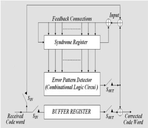
Step1. Received data is shifted into the buffer register and syndrome registers with switches SIN closed and SOUT open and error correction is performed with SIN open and SOUT closed.Step2. After the syndrome for the received code word is calculated and placed in the syndrome register, the contents are read into the error detector.Thedetector is a combinatorial circuit designed to output a ‘1’ if and only if the syndrome correspondsto a correctable error pattern with an error at the highest order position Xn-l. That,ifthe detector output is a '1' then the received digit
at the right most stage of the buffer register is assumed to be in error and will be corrected. If the detector output is '0' then the received digit at the right most stage of the buffer is assumed becorrect.Thus the detector output is the estimate error value for the digit coming out of the buffer register.
Fig 3.1 Error correction
3.1.2 ALGORITHM FOR DETECTING AND CORRECTING ERRORS
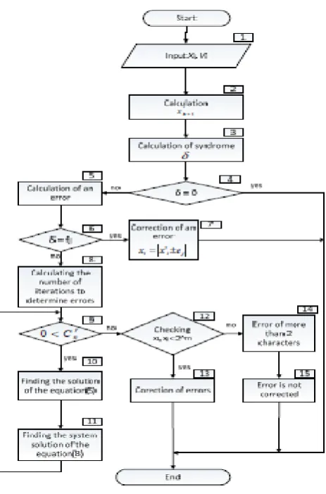
In modular correcting codes the error can be detected and corrected by the following algorithm.This algorithm of error detection and correction is shown in Figure 2. Offered information characters and relatively prime coefficients are introduced in bl. 1. Calculation character verification on downloaded data is in bl. 2. Value of the syndrome δ (bl. 3) is calculated as the difference between calculation and test accepted characters. If the value of the syndrome is 0 = δ (bl. 4), the error is not found, and if δ≠0 the error is detected and it can be corrected. To correct errors in one symbol the value P j i j f v e *= (bl. 5) is calculated, where i v - mutually prime coefficient, j e - error value, m j m e 2 2 − < <. In order to detect and correct errors the value syndrome δ and calculated value j f (bl. 6) are compared, if j f= δ , then the error is found and we can fix it using the formula i i j x x e = ± ' (bl. 7), and if j f≠ δ - this means that more than one character is available in this error message.
Available online: https://edupediapublications.org/journals/index.php/IJR/ P a g e | 159
the error is presenting in two or more characters (see a Figure 2). Let’s assume both errors are corrected and values i j x x , are not found (see a Fig. 1) which are belonging to a working range, i.e. they are less than m2. In such case it means that errors exist in two or more characters. The encoder working version is described in Verilog and implemented on the FPGA, Altera. The The developed technique of error correction can be applied to improve the efficiency of wireless sensor networks [8] as well as to ensure a defense from computer attacks [9] by implementing the integration of channel coding and encryption using the modular correcting codes and two-dimensional control errors. This data encryption will take place at the stage of forming the two-dimensional data matrix for errors control.
.
Fig.2.Error detection and correction process
Fig.3. Block diagram of encoder
IV.EXPERIMENTAL RESULTS A.Schematic Diagram:
Fig 4. Schematic for error detector and corrector
Fig.5. Technology schematic for error detector and corrector
Available online: https://edupediapublications.org/journals/index.php/IJR/ P a g e | 160
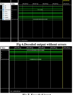
Fig 6.Decoded output without errors
Fig.7. Encoded input
Fig .6. Syndrome detection V. Conclusion:
Developed technique for correcting errors in two information symbols using just a single check character is offered. A block - diagram of the algorithm for error detection and correction and the decoder structure is developed as well. It was experimentally established that the proposed technique can speed up the code by about 18% and at the same time reduce the redundancy of the modular correcting code.
The two best codes utilize methods that allow for flexibility. Both turbo codes and LDPC codes require the use of a ”soft” decoder and they have can be adjusted to better work with specific code words. I would hypothesize that it is this flexibility that makes the difference and that future improvements will come from using increased amounts of flexibility.
REFERENCES
[1] A. Sikora. Web2.0 technology for an embedded web-based gateway platform for spatially distributed wireless networks, International Journal of Computing, (9) 1, 2010, pp. 31-36.
[2] V.Nithya, B.Ramachandran, B. Vidhyacharan. Energy efficient coded communication for IEEE 802.15. 4 compliant wireless sensor networks. Wireless personal communications, 2014, 77.1, pp. 675-690. [3] S. Howard, C. Schlegel, K. Iniewski. Error control coding in low-power wireless sensor networks: When is ECC energy-efficient?. EURASIP Journal on Wireless Communications and Networking, 2006.2, pp. 29-43. [4] M. C. Vuran, I. F. Akyildiz, Error control in wireless sensor networks: a cross layer analysis, IEEE/ACM Transactions on Networking, (17) 4 (2009), pp. 1186-1199.
[5] Z. Tian, D.F. Yuan, Q.Q. Liang, Energy efficiency analysis of error control schemes in wireless sensor networks, in Proceedings of the IEEE International Wireless Communications and Mobile Computing Conference IWCMC'08, 2008, pp. 401-405.
[6] N. Abughalieh, K. Steenhaut, A. Nowé, Low power channel coding for wireless sensor networks, in Proceedings of the 17th IEEE Symposium on Communications and Vehicular Technology in the Benelux SCVT’2010, 2010, pp. 1-5.
[7] N.Alrajeh et al. Error Correcting Codes in Wireless Sensor Networks: An Energy Perspective. Applied Mathematics & Information Sciences, 2015, 9.2, pp.809-818.