Tao Zhong*, Hou Zhang, Xue-Liang Min, Qiang Chen, and Guo-Cheng Wu
Abstract—A wideband frequency selective surface (FSS) with a sharp band edge is proposed. The periodic cell includes a mushroom-like cavity and four L-type slots etched on the top and bottom conductor claddings of the cavity. The measured results show that the proposed FSS operates at X band with a 12.5% bandwidth (7.85–8.90 GHz), in which the insertion loss is less than 3 dB. Comparing with the FSSs based on substrate integrated waveguide cavity, the proposed FSS not only realizes high selectivity, but also realizes a 55.8% reduction in cell size.
1. INTRODUCTION
As spatial filters in microwave and optics, frequency selective surfaces (FSSs) are composed of periodic structures in two dimensions [1–3]. The FSS technology has been widely applied to the design of low-RCS radomes, high-performance antennas, radar absorptive structure, reflectors, etc. [4–7]. In reality, design specifications of FSS are similar to filters designs in microwave circuitry. However, due to the restrictions of size and processing technology, high-performance FSS with higher-order selectivity characteristics is also difficult to realize in the applications [8–10].
In recent years, there are an increasing number of FSS designs with high selectivity characteristics following the development of substrate integrated waveguide (SIW) technology [11–14]. For the inherent high quality factor (Q-factor) of the SIW cavity, the FSSs based on SIW (SIW-FSSs) can achieve good frequency selectivity characteristics. However, the resonant frequency of SIW cavity strictly depends on the dimensions. The relative size of SIW-FSS is large, and the big size constrains its applications. In [11], Luo et al. presented lots of SIW-FSS for the first time, and an SIW-FSS with polarization rotation is presented by Simone et al. and Zuo et al. in [12, 13]. To reduce the cell size, quarter-mode substrate integrated waveguide (QMSIW) cavity is used in [14]. All the same, SIW-FSS or QMSIW-FSS is difficult to reduce the size further.
To reduce the size of cavity based FSSs, a novel cavity mushroom-like structure is proposed and applied to FSS design, simulation, fabrication and measurement in this paper. The mushroom-like cavity plays the equivalent role to an SIW cavity. Thus, the selectivity characteristics of the proposed mushroom-like cavity based frequency selective surface (MC-FSS) are similar to SIW-FSS. A transmission zero (TZ) appears near two transmission poles (TPs) to improve the passband characteristics of the MC-FSS. The measured results are in good agreement with the simulated ones.
2. FSS DESIGN AND ANALYSES
Physical dimensions of a unit cell are presented in Figure 1. A via hole connects the two metallic plates, and four L-type slots are etched on the top and bottom plates. The length of unit cell is L= 10 mm,
Received 3 July 2016, Accepted 14 September 2016, Scheduled 26 September 2016 * Corresponding author: Tao Zhong ([email protected]).
(a)
(b) (c)
Figure 1. Physical dimensions of a unit cell, (a) perspective view, (b) front view, (c) top view.
(b) (a)
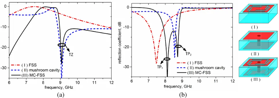
Figure 2. Simulated (a) transmission and (b) reflection coefficients of (I) the FSS, (II) the mushroom-like cavity and (III) the MC-FSS.
and the thickness of medium substrate is h = 0.5 mm. The length of metallic plate is C = 9.6 mm. The diameter of metallization via hole is D = 0.3 mm. The position and size of L-type slots depend on parameters l1 = 8.0 mm, l2 = 4.0 mm, d1 = 0.8 mm, d2 = 0.2 mm, andw = 0.3 mm. The MC-FSS is arranged on an FR4 substrate, with relative permittivity εγ = 4.4 and loss tangent δ = 0.001. All simulated results are from the electromagnetic simulation software CST MICROWAVE STUDIO.
Figure 2 shows the transmission and reflection coefficients of the FSS with four L-type slots in (I), a mushroom-like cavity without slots in (II) and the proposed MC-FSS in (III). In Figure 2(a), TZ at 9.08 GHz is generated by the coupling effect of the mushroom-like cavity resonance. It can be regarded as the result of self-cancelling effect along the L-type slots. In Figure 2(b), TP1 at 8.12 GHz mainly results from the slot resonance, while TP2 at 8.74 GHz mainly results from the cavity resonance perturbed by the L-type slots. In this case, the L-type slots not only perform as the equivalent magnetic wall of the mushroom-like cavity, but also provide a transmission zero near the resonant frequency of the mushroom-like cavity that improves the passband characteristics of the MC-FSS.
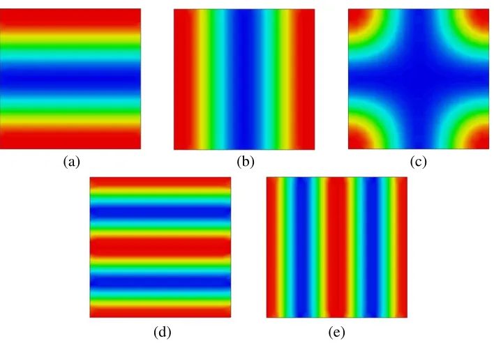
In order to further expound the mechanism of the mushroom-like cavity, the electric field distributions of TM100, TM010, TM110, TM200 and TM020 modes in foursquare cavity that takes the magnetic wall as boundary are plotted in Figure 3. The TM100 and TM010are degenerate modes, as well as TM200 and TM020. For the mushroom-like cavity, TM200 and TM020 modes are restricted because of the metallization via hole.
(d) (e)
Figure 3. Electric field distributions of (a) TM100, (b) TM010, (c) TM110, (d) TM200, and (e) TM020 modes.
presented in formula (1):
fr,mn= c0 2√μrεr
m W 2 + n L 2 (1)
In formula (1), εr, μr and c are relative dielectric constant, relative magnetic permeability and velocity of electromagnetic wave in free space, respectively. W and L are width and length of the rectangular cavity [11].
For the same size, cavity structures with magnetic wall boundary support TM100 and TM010modes of electromagnetic field distribution, and the corresponding resonant frequencies of these two modes are lower than the lowest resonant frequency of substrate integrated waveguide cavities. Therefore, smaller FSS can be designed based on the cavity structures.
The approximate resonant frequency of the L-type slots is given in formula (2):
fs= 2 ( c0
l1+l2)√εeff
(2)
whereεeff is the equivalent dielectric constant [6].
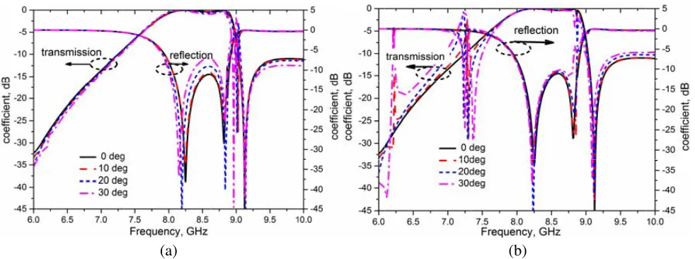
Since the TP1mainly results from slot resonance and depends on formula (2), small variation of slot length should have influence on TP1. Changing parameter l1, transmission and reflection coefficients of MC-FSS are shown in Figure 4(a). Asl1 increases, TP1 will decrease, while TP2 and TZ have scarcely any change because the changes of l1 have no influence on the structure of a mushroom-like cavity. Changing parameter d1, transmission and reflection coefficients of MC-FSS are shown in Figure 4(b). As d1 increases, TP2 will increase, while TP1 has scarcely any change because the change of d1 has little influence on the structure of L-type slots.
To further understand the dependence of the TPs or TZ on different sections of the unit cell, the current distributions on the surface at 8.12 GHz, 8.74 GHz and 9.08 GHz are plotted in Figure 5. The most surface current distributes on the slots at 8.12 GHz, while the surface current distributes on the cavity surface at 8.74 GHz and 9.08 GHz. Therefore, TP1 depends on the slot structure, and TP2 and TZ depend on the cavity structure.
(b) (a)
Figure 4. Transmission and reflection coefficients of MC-FSS with different structure parameters, (a)
l1, (b)d1.
(b)
(a) (c)
Figure 5. Current distributions on the surface at (a) 8.12 GHz, (b) 8.74 GHz and (c) 9.08 GHz.
(b) (a)
Figure 7. Fabricated prototypes of MC-FSS. Figure 8. Comparisons between the measured and the simulated.
The measured results in the laboratory and the simulated results from software are both plotted in Figure 8. It is proper because the processing error of fabricated prototypes or the unsteady test condition that the measured reflection is more than−10 dB. In the test curve, the two measured transmission poles centre at 8.11 GHz and 8.74 GHz, and the measured transmission zero centers at 9.12 GHz. The FSS cell is 10×10 mm2that amounts to 0.28λ0×0.28λ0, whereλ0 is free space wavelength at resonant frequency, and it realizes a 55.8% reduction in cell size compared with FSS based on SIW cavity presented in [11]. Comparing the results from CST MICROWAVE STUDIO, the transmission poles and transmission zero scarcely have error. The 3 dB bandwidth of the fabricated prototype is 12.5% (7.85–8.90 GHz), and it is little less than the simulated results of 15.3% (7.60–8.86 GHz).
4. CONCLUSION
A novel FSS based on a mushroom-like cavity has been presented and measured. Like the response of SIW-FSS, two transmission poles emerge at X-band, and one transmission zero is located at upper sideband. Compared with the conventional SIW-FSS [11], the MC-FSS realizes not only good selectivity, but also a 55.8% reduction in cell size. In addition, the MC-FSS is simple to be fabricated for the signal-layer structure and with thin thickness.
REFERENCES
1. Munk, B. A., Frequency Selective Surfaces: Theory and Design, Wiley, New York, 2000. 2. Munk, B. A., Finite Antenna Arrays and FSS, John Wiley and Sons, Inc., 2005.
7. Zheng, J. and S.-J. Fang, “A new method for designing low RCS patch antenna using frequency selective surface,”Progress In Electromagnetics Research Letters, Vol. 58, 125–131, 2016.
8. Li, M. and B. Nader, “A third-order bandpass frequency selective surface with a tunable transmission null,” IEEE Transactions on Antennas and Propagation, Vol. 60, No. 4, 2109–2113, Apr. 2012.
9. Rashid, A. K., Z. Shen, and B. Li, “An elliptical bandpass frequency structure based on microstrip lines,”IEEE Transactions on Antennas and Propagation, Vol. 60, No. 10, 4661–4669, Oct. 2012. 10. Shi, Y., W. Zhuang, W. Tang, and C. Wang, “Modeling and analysis of miniaturized
frequency-selective surface based on 2.5-dimensional closed loop with additional transmission pole,” IEEE Transactions on Antennas and Propagation, Vol. 64, No. 1, 346–351, Jan. 2016.
11. Luo, G., W. Hong, Z. Hao, B. Liu, W. Li, J. Chen, H. Zhou, and K. Wu, “Theory and experiment of novel frequency selective surface based on substrate integrated waveguide technology,” IEEE Transactions on Antennas and Propagation, Vol. 53, No. 12, 4035–4043, Dec. 2005.
12. Simone, A. W., W. Hong, B. Maurizio, and K. Wu, “Polarization rotating frequency selective surface based on substrate integrated waveguide technology,” IEEE Transactions on Antennas and Propagation, Vol. 58, No. 4, 1202–1213, Apr. 2010.
13. Zuo, Y., Z. Shen, and Y. Feng, “Frequency-selective microwave polarization rotator using substrate integrated waveguide cavities,” Chinese Physics B, Vol. 23, No. 3, 034101, 2014.