A Novel Tunable Microstrip Patch Antenna Using Liquid Crystal
Jia-Wei Dai*, Hong-Li Peng, Yao-Ping Zhang, and Jun-Fa Mao
Abstract—This paper presents a novel tunable microstrip patch antenna using liquid crystal. It adopts a differentially-driven, aperture-coupled, and stacked-patch structure. Compared with the conventional design, this novel antenna achieves a larger frequency tuning range, much wider impedance bandwidth, higher radiation efficiency and gain. Besides, the novel antenna facilitates the bias design as the bias signal is naturally isolated from the RF signal. Both the conventional and novel antennas are designed to operate at 28 GHz using an RT/Duroid 5880 substrate and K15 liquid crystal. Results show that the novel antenna has a tuning range of 3.1%, an impedance bandwidth of 6.43%, a peak radiation efficiency of 70%, and a peak realized gain of 6.5 dBi, while the conventional antenna has the tuning range of 2.7%, impedance bandwidth of 3.57%, peak radiation efficiency of 45%, and peak realized peak gain of 4.5 dBi.
1. INTRODUCTION
Tunable antennas are desirable for modern wireless communication systems for the better use of frequency spectrum. In this context, tunable antennas have been studied intensively [1–12]. A key factor in designing tunable antennas is the technology used for realizing the tunability. The available technologies include radio frequency microelectromechanical systems (RF-MEMS) [1, 2], semiconductor solutions [3, 4] and tunable dielectrics such as ferroelectric [5, 6] and liquid crystal (LC) [7–12]. Among them, the LC technology is a promising one, because the dielectric loss of LC decreases with increasing frequency, and the manufacturing technology is mature [13].
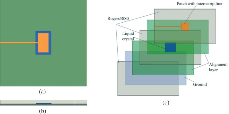
Tunable antennas using LC are usually designed in a microstrip patch antenna structure [9–12]. The microstrip patch antenna structure has two layers of substrates and one layer of superstrate. The microstrip patch together with the microstrip feedline is printed on the bottom surface of the superstrate layer. A cavity is formed in the top substrate layer into which the LC is injected. The ground plane is printed on the top surface of the bottom substrate layer. The LC is biased with a direct current (DC) voltage applied between the patch and the ground plane. Typical LC materials are E7 and K15, developed for LC display. There has been effort taken by the material community to develop new LC for RF and microwave products. Unfortunately, they are not yet commercially available in the market or cheap enough to use for commercial applications. Hence, we focus our effort on the improvement of tunable microstrip antenna structure rather than the properties of LC. We present the design and analysis in this paper, and describe the conventional and novel tunable microstrip patch antennas using the liquid crystal in Section 2. We examine the relationship between the orientation of the LC molecules and the bias voltage in Section 3, and discuss and compare the simulated antenna performances in Section 4. Finally, we draw the conclusions in Section 5.
Received 5 December 2016, Accepted 21 January 2017, Scheduled 8 February 2017
* Corresponding author: Jia-Wei Dai ([email protected]).
the patch and ground plane. Both bias and RF signals exist simultaneously on the microstrip line. To avoid the detrimental effect on both the DC and RF sources, a bias tee needs to be used at the input of microstrip line.
(a)
(b)
(c)
Figure 1. The conventional tunable microstrip patch antenna using the LC: (a) top view, (b) side view, and (c) perspective view.
(a)
(b)
(c)
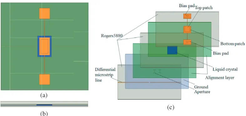
Figure 2. The novel tunable microstrip patch antenna using the LC: (a) top view, (b) side view, and (c) perspective view.
microstrip antenna, so the radiation efficiency of the differentially-driven microstrip antenna can be much higher than that of the single-ended counterpart [15], differentially driving operation is used in the novel antenna so that the radiation efficiency is higher. It is particularly suitable for highly-integrated solutions of modern wireless systems [17–19].
3. TUNABLE MECHANISM USING LIQUID CRYSTAL
The operating frequency of a microstrip patch antenna depends on the dielectric constant of its substrate. If the dielectric constant of the substrate can be changed, the operating frequency of the microstrip patch antenna can thus be tuned. The tunable mechanism of a microstrip patch antenna using the LC is illustrated in Fig. 3. As shown in Fig. 3(a), LC molecules are out of order when no alignment layer and bias voltage are applied. When alignment layers are applied as in Fig. 3(b), LC molecules tend to be ordered. They are parallel to the alignment layer, and the dielectric constant of the LC is ε⊥. As the bias voltage is applied and increased to the maximum as in Fig. 3(c), the LC molecules tend to be inclined and parallel to the electric field between the patch and ground, and the dielectric constant of LC tends to be ε. So the permittivity of LC can be continuously tuned from ε⊥ to ε when a DC bias voltage is applied and increased between the patch and the ground plane as in Fig. 3(d).
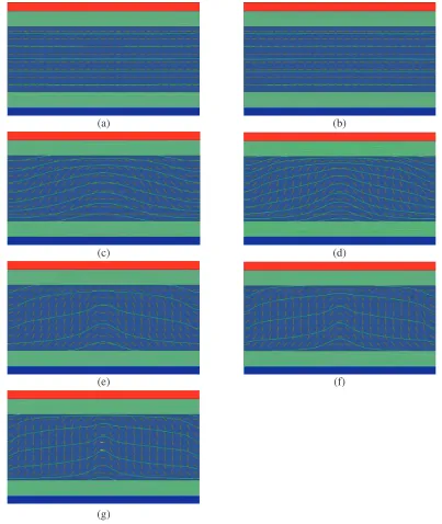
The LC used is type K15. Its dielectric constant can be continuously tuned from εr,⊥ = 2.72 to εr, = 2.9 in the 28-GHz band, and its loss tangent is about 0.03. The relationship between the orientation of the LC molecules and the bias voltage is simulated with the software DIMOS.2D to determine how much bias voltage needs to be applied. The simulated structure simplified from the antenna structures shown in Figs. 1 and 2 is shown in Fig. 4. The LC layer is 0.127-mm, the alignment layer 0.03-mm, and the metal patch and ground plane are 0.017-mm thick, respectively. By varying the bias voltage applied between the patch and ground plane, we can view from Fig. 5 the relationship between the orientation of the LC molecules and the bias voltage. Note that the green lines represent the equipotential lines.
As shown in Fig. 5, the bias voltage that causes LC molecules starting to incline is around 2–3 V, and the bias voltage that causes LC molecules stopping inclining is around 6–7 V. So if the bias voltage is smaller than 2 V, εr = 2.72, and if the bias voltage is equal to or bigger than 7 V, εr= 2.9, when the bias voltage is between 2 V and 7 V,εr can be approximately calculated by [20]:
εr=εr,⊥+ Δεsin2ϕ (1)
whereϕ denotes the inclined angle of the LC molecules, and Δεdenotes the value given by [20]:
(a) (b)
(c) (d)
Figure 3. Illustration of tunable mechanism using the LC: (a) no alignment layer and bias voltage applied, (b) only alignment layer applied, (c) both alignment layer and maximum bias voltage applied, and (d) both alignment layer and bias voltage applied.
Figure 4. Simulated structure for LC molecules with a bias voltage.
4. RESULTS AND DISCUSSION
(a) (b)
(c) (d)
(e) (f)
(g)
Figure 5. The orientation of LC molecules to the applied bias voltage: (a) to (g) for the bias voltage from 0 to 7 Volts.
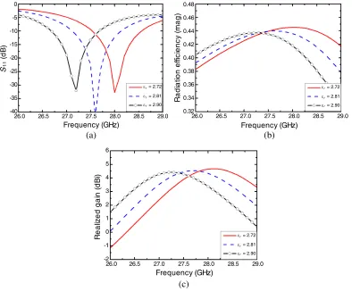
The simulated results of the conventional tunable microstrip patch antenna are shown in Fig. 6. The microstrip patch has a size of 3.1×5.6 mm2. The microstrip line is designed for 50 Ω. Note from Fig. 6(a) that the simulated peak matched frequency changes from 28 GHz at 0 V to 27.25 GHz at 7 V, indicating a tuning range of 2.7%. The 10-dB impedance bandwidth is about 1 GHz (or 3.57% at 28 GHz). It is evident from Figs. 6(b) and (c) that the simulated peak radiation efficiency is 45%, and the peak realized gain is 4.5 dBi at 28.25 GHz at 0 V.
The simulated results of the novel tunable microstrip patch antenna are shown in Fig. 7. The upper and lower patches have sizes of 2×4 mm2 and 2.7×4.4 mm2, respectively. The opening in the ground
26.0 26.5 27.0 27.5 28.0 28.5 29.0 -40 -35 -30 -25 -20 -15 -10 -5 0 S (d B ) Frequency (GHz)
26.0 26.5 27.0 27.5 28.0 28.5 29.0 0.32 0.34 0.36 0.38 0.40 0.42 0.44 0.46 0.48 R a di a ti on e ff ic ie n c y ( m a g ) Frequency (GHz)
26.0 26.5 27.0 27.5 28.0 28.5 29.0 -2 -1 0 1 2 3 4 5 6 R e a liz e d g a in (d B i) Frequency (GHz) 11 (a) (b) (c)
ε r= 2.72
ε = 2.81
ε = 2.90 r r
ε r= 2.72
ε = 2.81
ε = 2.90 r r
ε r= 2.72
ε = 2.81
ε = 2.90 r r
Figure 6. Simulated results for the conventional tunable microstrip patch antenna: (a) |S11|, (b)
radiation efficiency, and (c) peak realized gain.
26.0 26.5 27.0 27.5 28.0 28.5 29.0 29.5 30.0 -40 -35 -30 -25 -20 -15 -10 -5 0 S (d B ) Frequency (GHz)
26.0 26.5 27.0 27.5 28.0 28.5 29.0 29.5 30.0 0.0 0.1 0.2 0.3 0.4 0.5 0.6 0.7 0.8 R a d iat io n ef fici en cy ( m ag )
Frequency (GHz)
11
(a) (b)
r
ε = 2.81
ε = 2.90
ε = 2.72
r r
ε = 2.81
ε = 2.90
ε = 2.72
26.0 26.5 27.0 27.5 28.0 28.5 29.0 29.5 30.0 -12
-10 -8 -6 -4 -2 0 2 4 6 8
R
e
a
liz
e
d
g
a
in
(d
B
i)
Frequency (GHz)
(c)
ε = 2.81
ε = 2.90
ε = 2.72 r r r
Figure 7. Simulated results for the novel tunable microstrip patch antenna: (a) |S11|, (b) radiation
efficiency, and (c) peak realized gain.
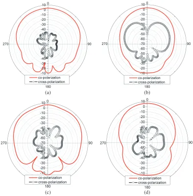
(a) (b)
(c) (d)
5. CONCLUSION
A novel tunable microstrip patch antenna using the liquid crystal is proposed for the first time in this paper. Because the differentially-driven, aperture-coupled, and stacked-patch structure is adopted, this novel antenna achieves a larger frequency tuning range, much wider impedance bandwidth, higher radiation efficiency and gain than the conventional design. Besides, the novel antenna facilitates the bias design as the bias signal is naturally isolated from the RF signal. Both the novel and conventional antennas are designed to operate at 28 GHz using an RT/Duroid 5880 substrate and K15 liquid crystal. Results show that the novel antenna has a tuning range of 3.1%, an impedance bandwidth of 6.43%, a peak radiation efficiency of 70%, and a peak realized gain of 6.5 dBi, while the conventional antenna has the tuning range of 2.7%, impedance bandwidth of 3.57%, peak radiation efficiency of 45%, and peak realized gain of 4.5 dBi.
ACKNOWLEDGMENT
This work was supported in part by the 863 Program of China under Grant No. 2015AA01A703.
REFERENCES
1. Erdil, E., K. Topalli, and M. Unlu, “Frequency tunable microstrip patch antenna using RF MEMS technology,” IEEE Trans. Antennas and Propagation, Vol. 55, No. 4, 1193–1196, April 2007. 2. Caekenberghe, K. V. and K. Sarabandi, “A 2-bit Ka-band RF MEMS frequency tunable slot
antenna,” IEEE Antennas and Wireless Propagation Letters, Vol. 7, 179–182, March 2008.
3. Qin, P. Y., F. Wei, and Y. J. Guo, “A wideband-to-narrowband tunable antenna using a reconfigurable filter,”IEEE Trans. Antennas and Propagation, Vol. 63, No. 5, 2282–2285, May 2015. 4. Boukarkar, A., X. Q. Lin, and Y. Jiang, “A dual-band frequency-tunable magnetic dipole antenna for WiMAX/WLAN applications,” IEEE Antennas and Wireless Propagation Letters, Vol. 15, 492–495, July 2015.
5. Sazegar, M., Y. L. Zheng, H. Maune, C. Damm, X. H. Zhou, J. Binder, and R. Jakoby, “Low-cost phased-array antenna using compact tunable phase shifters based on ferroelectric ceramics,”IEEE Trans. Microwave Theory and Techniques, Vol. 59, No. 5, 1265–1273, May 2011.
6. Lovat, G., P. Burghignoli, and S. Celozzi, “A tunable ferroelectric antenna for fixed-frequency scanning applications,”IEEE Antennas and Wireless Propagation Letters, Vol. 5, No. 1, 353–356, December 2006.
7. Missaoui, S., A. Gharbi, and M. Kaddour, “Design and simulation reconfigurable liquid crystal patch antennas on foam substrate,”Journal of Chemical Engineering & Materials Science, Vol. 2, No. 7, 96–102, 2011.
9. Papanicolaou, N. C., M. A. Christou, and A. C. Polycarpou, “Frequency-agile microstrip patch antenna on a biased liquid crystal substrate,” Electron. Lett., Vol. 51, No. 3, 202–204, February 2015.
10. Polycarpou, A. C. and M. A. Christou, “Tunable patch antenna printed on a biased nematic liquid crystal cell,” IEEE Trans. Antennas and Propagation, Vol. 62, No. 10, 4980–4987, July 2014. 11. Liu, L. and R. J. Langley, “Liquid crystal tunable microstrip patch antenna,” Electron. Lett.,
Vol. 44, No. 20, 1179–1180, September 2008.
12. Missaoui, S., S. Missaoui, and M. Kaddour, “Reconfigurable microstrip patch antenna based on liquid crystals for microwave applications,” Proceedings of Engineering&Technology, 23–28, 2016. 13. Deo, P., D. M. Syahkal, L. Seddon, S. E. Day, and F. A. Fern´andez, “Microstrip device for broadband (15–65 GHz) measurement of dielectric properties of nematic liquid crystals,” IEEE Trans. Microwave Theory and Techniques, Vol. 63, No. 4, 1388–1398, April 2015.
14. Gao, S. C., L. W. Li, M. S. Leong, and T. S. Yeo, “A broad-band dual-polarized microstrip patch antenna with aperture coupling,”IEEE Trans. Antennas and Propagation, Vol. 51, No. 4, 898–900, April 2003.
15. Zhang, Y. P., “Design and experiment on differentially-driven microstrip antennas,” IEEE Trans. Antennas and Propagation, Vol. 55, No. 10, 2701–2708, October 2007.
16. Rathi, V., G. Kumar, and K. P. Ray, “Improved coupling for aperture coupled microstrip antennas,” IEEE Trans. Antennas and Propagation, Vol. 44, No. 8, 1196–1198, August 1996.
17. Choudhary, N., A. Tiwari, J. S. Saini, V. K. Saxena, and D. Bhatnagar, “Planar arrangement of modified concentric rings with defected ground for mobile and wireless communication systems,” Progress In Electromagnetics Research B, Vol. 47, 161–169, 2016.
18. Islam, M. T., M. N. Shakib, and N. Misran, “Broadband E-H shaped microstrip patch antenna for wireless systems,” Progress In Electromagnetics Research, Vol. 98, 163–173, 2009.
19. Eldek, A. A., A. Z. Elsherbeni, and C. E. Smith, “Dual-wideband square slot antenna with a U-Shaped printed tuning stub for personal wireless communication systems,” Progress In Electromagnetics Research, Vol. 53, 319–333, 2005.