Available online:
http://edupediapublications.org/journals/index.php/IJR/
P a g e | 3166Design of Low Power and Low Latency Novel
Scheme for Network on Chip
Y. L. Ajay Kumar
1, Dr. D.Satyanarayana
2& Dr. D. Vishnu Vardhan
31
Research Scholar, Dept of ECE, JNTUA,Anantapur, AP, India .
2Professor & Controller of Examinations, RGMCET, Nandyal, AP, India.
3
Assistant Professor, Dept of ECE, JNTUA,Anantapur, AP, India.
Abstract:
Network-on-chip (NoC) has emerged as a scalable and promising solution to global communications within large multi core systems. The NoC with virtual point-to-point connections (VIP)is the existing, the proposed Novel scheme can reduce the latency along with the power. A path allocation algorithm is proposed in this paper to determine VCS connections and circuit-switched connections on a mesh connected NoC, such that both communication latency and power are optimized. A novel switching mechanism, called virtual circuit switching, is proposed to intermingle with circuit switching and packet switching. Flits travelling in virtual circuit switching can traverse the router with only one stage. In addition, multiple virtual circuit-switched (VCS) connections are allowed to share a common physical channel.
Keywords
Network-on-chip (NoC), virtual point-to-point connections, circuit-switched connections, virtual circuit switching, Novel Scheme.
1.
Introduction
A bus arbiter controls access to the shared resource by granting access to only one of the several requesting masters. There are several disadvantages associated with these kind of communication architectures. Both point-to-point as well as bus based communication schemes are not very scalable and cannot efficiently handle the communication requirements of modern SoC architectures. The performance of a bus degrades as the number of requestors connected to the bus increases. This can be attributed to the fact that the bandwidth of the communication channel is shared among all the bus requestors. This results in the serialization of the requests to the bus, thus increasing communication latencies. Also, the complexity and the delay of the
arbiter increases as the number of requestors to the bus increases. Technology scaling has caused wire delay to become a dominant component of the overall clock cycle time [1]. Long wires in point-to-point links as well as buses result in increased delays and are susceptible to noise. Hence, on-chip communication using these schemes is becoming expensive in terms of both power as well as speed in the era of deep-submicron technologies (DSM).
Fig: 1. bus, point to point, NOC communication
Available online:
http://edupediapublications.org/journals/index.php/IJR/
P a g e | 3167 memristance without continues applying voltage.When bipolar voltage is applied then the memristor exhibit hysteresis curve in V-I characteristics. This pinched hysteresis is fingerprint for memristor. When the input voltage is kept in the operating region (Vin < |Vths| and |Vthr|), the device stays in its current state. Setting the input voltage outside of the operation region, past a threshold value, the device enters into the switching region, (Vin > |Vths| and |VTR|), with a subsequent changing of its state (ON to OFF, or OFF to ON). The NoC is a highly scalable packet based communication architecture that over- comes the disadvantages of the bus based communication systems. Table I compares the bus based and No based on-chip communication schemes and has been adapted from You et al. . NCOs help to accomplish the transfer of maximum amount of information between communicating nodes within the least possible time. NCOs consist of routing elements connected by small point-to-point links forming a data routing network on chip.
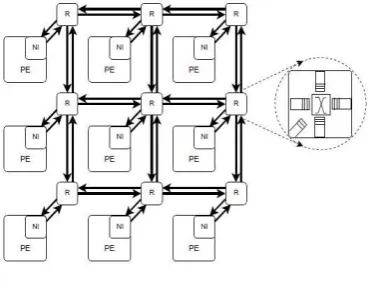
Unlike bus architectures, where the bus is occupied by one source node during the entire message transaction, the use of packet based communication in No allows for sharing of the links between various communicating nodes. This increases throughput and reduces communication latencies. No can be easily scale by connecting additional routing elements to the existing network. The aggregate bandwidth of the network scales with increasing network size. NCOs support design reuse as the same routing element can be used to scale the No to higher dimensions. This reduces the time-to-market and validation costs. Thus, NCOs offer a highly ancient communication infrastructure for modern day SoC and Multi core architectures. Figure 1 shows some examples of bus, point-to-point and No based communication architectures. Computational elements from the communication infrastructure. NIs convert the messages generated by the PEs into packets and insert additional routing information based on the architecture of the under
Figure:2 NOC Architecture
lying network. Packets are decomposed into smaller units called flow control units or its which are transmitted over the network. Flits are further classified as head, body and tail its. The head it carries the routing information required to route the packet to its destination. The head it allocates resources for the entire packet as it traverses from so urce to destination. The body and tail its carry only the packet payload with no routing information and follow the head it through the network. The tail it de-allocates the resources which have been allocate d to the packet by the
head it. Routing Nodes are the heart of the communication network.
They route the packets onto the appropriate link so that they can reach the intended destination. Routing protocols in conjunction with the routing information in the packet header are used to make routing decision at each routing node. Channels or Links connect the routing nodes in an Two links are present between any two routers in the network, one each for data transmission in each direction. Links provide the bandwidth required for data transmission. In addition to the data transmission links, additional links required for control may also be present.
Figure 2 depicts these component s for a 4x4 NoC where the routing nodes connected as a grid.
Available online:
http://edupediapublications.org/journals/index.php/IJR/
P a g e | 3168 connect the processing elements to the main on-chipcommunication network. They decouple theThe common physical channel is shared by all the nodes commonly to communicate with multiple nodes. Each node has more than one communication router by this the packet will get interference between the nodes because more than one packet is passing through the nodes. The nodes are represent in the form of (x,y) where x is the source node and y is the destination node
2. Proposed Hybrid Scheme Based on
Virtual Circuit Switching
The basic principle of the proposed hybrid scheme is that VCs are exploited in virtual circuit switching to form a number of VCS connections and multiple VCS connections can share a common physical channel. In this hybrid scheme, VCS connections cooperate with PS
Fig:2. Simple traffic with communication routes in a 4 × 4 mesh.
Fig:3. CS and PS connections of the conventional hybrid scheme
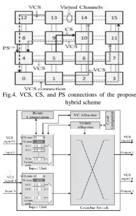
Fig.4. VCS, CS, and PS connections of the proposed hybrid scheme
Fig. 5 Router Architecture
and CS connections at the same time, modified router architecture with five ports is proposed, as shown in Fig. 5. Compared with the baseline router [12], the additional hardware of the proposed router includes the bypass path, the circuit configuration, and the VCS state.
Available online:
http://edupediapublications.org/journals/index.php/IJR/
P a g e | 3169 Circuit Switching. The proposed hybrid schemesupports the interweaving of packet switching, circuit switching, and virtual circuit switching. Two extra bits are added to each flit to denote the switching type of the flit. When a flit enters the router, these extra bits are checked at first. Then, the corresponding router pipeline is executed according to the switching type of the flit. Operations of circuit switching in this paper are similar to [6]. This section mainly describes operations of virtual circuit switching. Note that VCS connections must be constructed in advance before the flit traveling in virtual circuit switching. Fig. 2 shows an example of traffic, in which physical channels (1, 2), (7, 11), and (8, 4) are shared by more than one communication, respectively. (x, y) denotes the physical channel from node x to node y. Fig. 3 shows CS connections and PS connections after using the conventional hybrid scheme. A CS connection is configured by recording in each router which input port should be connected to which output port. It is composed of physical channels and routers.
However, routers on a PS connection are configured during the (BW, RC, VA, and SA) stages when flits require passing through. A physical channel can be shared by one CS connection and multiple PS connections. Once flits on CS connections arrive at routers, crossbar switches are immediately configured so that the CS flits can bypass directly to the ST stage [4]–[6]. When there is no CS flit, the corresponding ports of crossbar switches are released to PS connections. Fig. 4 shows VCS, CS, and PS connections of the proposed hybrid scheme. A VCS connection comprises VCs and routers that have been configured by recording in each router which input VC should be connected to which downstream VC. Crossbar switches of routers are preconfigured during the SA stage before VCS flits require passing through. Because VCS connections are established over VCs, a physical channel can be shared by n VCS connections at most (n is equal to the VC number). Other communications competing for that physical channel must be executed in packet switching, such as the communication from node 8 to node 4 in Fig. 4.
3. Simulation Results
The simulation results for router is shown in the figures :6&7 below
Figure:6. Simulation results for cross bar
Figure:7. Simulation Results for Router
5. Conclusion
Available online:
http://edupediapublications.org/journals/index.php/IJR/
P a g e | 3170 mesh-connected NOCs, such that the average packetlatency and energy consumption are both optimized. Our future work will focus on extending the current work to support applications with unpredictable communication pat-terns. Other extensions include the fault tolerance, the quality-of-service (QoS) operation, the multicast delivery service, and the mapping, scheduling of applications based on virtual circuit switching
6. References
[1] Phi-Hung Pham, “Design and Implementation of an on-chip permutation network for Multiprocessor System-on-Chip” IEEE
Transferee large scale integration (VLSI) systems,Vol.21.No.1, Page No-173- 177,January 2013.
[2] Bill Cordan, Palmchip Corporation An efficient bus architecture for system-on-chip design Custom integrated Circuits, 1999.
[3] Sibabrata Ray, Hong Jiang. A reconfigurable bus structure for multiprocessors with bandwidth reuse, Journal of Systems Architecture 45, 1999
[4] Hammond Lance, Olukotun Kunle. Considerations in the Design of Hydra: A Multiprocessor-on-a- Chip Micro architecture, Stanford Technical Report CSL-TR-98-749, Stanford University, 1998.
[5] Lars-Hugo Hemert Digital kretsar, Student literature, Lund, 1996, ISBN 91-44-00099-5. [6] John L. Hennessy, David A. Patterson Computer
Architecture A Quantitative Approach, second edition, Morgan Kaufmann Inc, San Francisco California, 1996, ISBN 55860-329-8.
[7] Vincent P. Hearing & Harry F. Jordan Computer Systems Design and Architecture, Addison Wesley, California, 1997, ISBN 0-8053-4330-X. [8] Howard Sachs, Mark Birnbaum VSIA Technical Challenges Custom Integrated Circuits, 1999. Proceedings of the IEEE 1999 , 1999 , Page(s): 619 -622
[9] Geert Rousseel, Sonics Inc. Decouple core for proper integration eeTimes Jan 3, 2000. www.eetimes.com.story/OEG20000103S004 8 [10]Jon Turino, SynTest Technologies, Inc.
emphDesign for Test and Time to Market - Friends or Foes Test Conference, 1999. Proceedings. International, 1999 , Page(s): 1098 -1101
[11]Lewis, Je_. Intellectual Property (IP) Components, Artisian Components Inc. http://www.ireste.fr/fdl/vcl/ip/ip.htm
[12]Olukotun Kunle, Bergman Jules, Kun-Yung Chang and Basem Nayfeh. Rationale, Design
and Performance of the Hydra Multiprocessor, Stanford Technical Report CSL-TR-94-645, Stanford University, 1994.
[13]RealChip Custom communication Chips. System-on-Chips,
http://www.realchip.com/Systems-on-Chips/systems-on-chips.html
[14]Rincon Ann Marie, Cherichetti Cory, Monzel James. A, Staur David, R, Trick Michael, T. IBM Microelectronics Corp. Core Design and System-on-a-Chip Integration, IEEE Design & Test of Computers. Volume: 14 4 , Oct.-Dec. 1997, pp: 26{35
[15]Rincon Ann Marie, Lee William. R and Slattery Michael. IBM Microelectronics Corp. The Changing Landscape of System-on-Chip Design, Custom Integrated Circuits, 1999. Proceedings of the IEEE 1999, pp: 83