R E S E A R C H
Open Access
DME interference suppression algorithm
based on signal separation estimation
theory for civil aviation system
Jie Li
1, Renbiao Wu
2, Yun Hao
1*, Xihua Wang
1, Yali Wang
1and An Zhao
1Abstract
Using exclusively for civil aviation system, GPS (Global Positioning System) L5 signal is set up and takes up an appointed frequency band. However, the DME (distance measurement equipment) signal which has already applied for distance measurement in the civil aviation system works as the same frequency band as GPS L5 signal. As a forced high-power pulse interference, DME signal will decrease SINR (signal-to-interference and noise ratio) of GPS L5 signal and even give rise to failure of acquisition and tracking. In case the DME interferences come from more than one base station, the traditional DME interference suppression methods which bring about the loss of GPS signal will suffer from serious performance degradation. In the light of the received signal model, a new DME interference mitigation algorithm is presented in this paper. At first, frequency is estimated with tmwapDFT (time-modulated windowed all-phase DFT). Then, we use the estimated frequency to get amplitude and signal delay information by signal separation estimation theory. In addition, we consider the previous estimated results as the initial value, and a two-dimension search method is implemented in a small range for further improving the parameter estimation accuracy. Based on the estimated parameters, DME signal can be exactly reconstructed and then eliminated. It can be shown from the experiment results that the proposed method which keeps more useful signal has a better performance compared with the conventional ones.
Keywords:GPS L5 signal, DME interference mitigation, Time-modulated windowed all-phase DFT, Signal separation estimation theory, Precise estimation of parameters
1 Introduction
GPS (Global Positioning System) L5 signal with an ex-clusive frequency band is specially used for civil aviation system. Compared with L1 and L2 signal, L5 signal has higher power, more positioning accuracy, stronger anti-jamming capability, and can be implemented more conveniently. However, there are a lot of interference equipment working at the L5 frequency band, among which DME (distance measurement equipment) signals make greatest influence on L5 signal.
As forced high-power pulse interferences, DME signal will decrease SINR (signal-to-interference and noise ratio) at the receiver, reduce the acquisition satellite numbers, make the tracking loop unlocked, and finally
lead to the decoding error or failure of navigation infor-mation [1–4]. Therefore, it is very necessary to solve this problem in civil aviation systems.
Lots of research organizations and universities have been seeking for the methods to mitigate the error brought from DME interference. Pulse blanking, notch filter, and hybrid method are most often used among the developed anti-interference techniques. Pulse blanking method mitigates the interference by setting the signals which exceed the threshold to zero in time domain [5, 6]. It is easy to implement with less computation complexity and has already verified on experimental hardware re-ceiver [7]. However, it cannot thoroughly eliminate the bell-shaped interference pulse, leaving tails of the pulse buried under noise level. The main deficiency of this method is that some useful GPS signal will be got rid of as well when the interferences are suppressed. Owing to high density of DME signal, this method will * Correspondence:[email protected]
1Zhonghuan Information College Tianjin University of Technology, Tianjin,
China
Full list of author information is available at the end of the article
eliminate a large part of GPS signal. Acquisition and tracking error will be brought from a great amount of data missing.
Notch filter method mitigates the interference by let-ting the signal pass a narrow band notch filter involving DME frequencies [5, 8]. Both the central part and the tail part of bell-shaped interferences can be thoroughly suppressed with this method because the DME signal only exists on some special frequencies. Although the frequency domain method can maintain more useful signal than pulse blanking method, there are also some useful signals eliminated.
The hybrid method uses a moving window in time domain to detect the DME pulse interference. When the DME pulse is detected, the data section will be transformed to frequency domain and be filtered. The filtered data should then be converted back to time do-main instead of the originals [5, 9]. The hybrid method combines the two mentioned methods together and preserves more useful signals, but the data missing problem still exists.
The above methods eliminate the interference in time or frequency domain, and at the same time, the useful signal will suffer from loss more or less to a certain ex-tent. In this paper, we propose a new DME interference suppression method which can keep useful GPS signal to a large extent meanwhile suppress the interference. Hence, DME signal can be reconstructed and eliminated without losing much SNR. The efficiency of the proposed approach is verified in the experiments.
2 Data model and problem description
DME baseband signal is a pulse pair which can be modeled as:
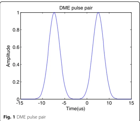
s tð Þ ¼e−α=2ðt−Δt=2Þ2þe−α=2ðtþΔt=2Þ2 ð1Þ where α= 4.5 × 10¹¹s−2 determines the width of the pulse pair and Δt= 12 × 10−6s determines the interval. The half-amplitude width of each single pulse is 3.5 μs, and the interval between two single pulses is 12 μs. The waveform of the DME pulse pair is shown in Fig.1.
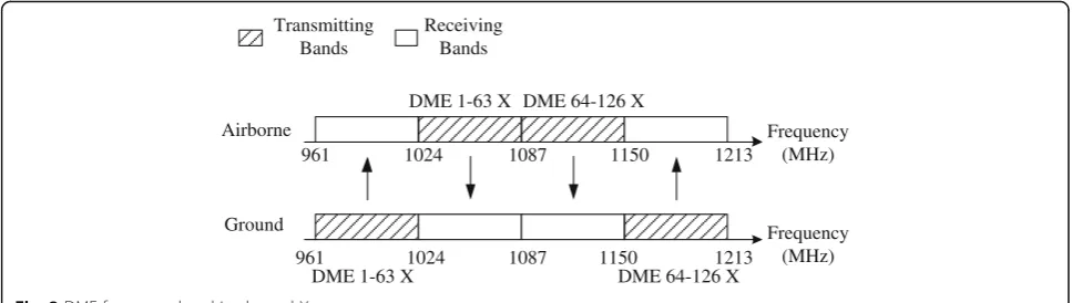
Ranged from 962 to 1213 MHz, the DME frequency band is divided into two channels, X and Y. Take X channel as an example, when the airborne DME interro-gator transmits signals in channel 1–63 X, the ground DME transponder will use the frequency which is 63 MHz lower than the interrogator frequency ranged from 962 to 1024 MHz. Nevertheless, the ground trans-ponder frequency is 63 MHz higher than the interroga-tor frequency when the airborne interrogainterroga-tor works at the 64-126 X channel. The frequency band in channel X is shown in Fig. 2.
When the airborne DME equipment takes advantage of the 64–126 X channel for communication, the ground equipment may respond frequencies ranged from 1151 to 1213 MHz. Unfortunately, this frequency band covers the GPS L5 signal with central frequency 1176.45 MHz and bandwidth 24 MHz.
Generally, DME interrogators send 5 to 150 pulse pairs per second, and the peak power varies from 50 W to 2 kW. The maximum of the pulses from transponder may be up to 2700 per second. Thus, DME signal from the ground is a strong jamming to GPS L5. It will seriously cut down the GPS receiver SINR and then cause the acquisition, tracking, and positioning errors. Therefore, it is necessary to solve DME interference suppression problem.
When the airplanes are near the ground base of DME, the airborne GPS receiver will be interfered by the pulses sent by DME ground base stations. Owing to the relative movement between the airplane and DME station, Doppler frequency shift must be taken into account. When the GPS receiver is interfered by only one DME base station, the interference can be elimi-nated by the method based on the NLS (nonlinear least squares) criterion [10]. In case the DME pulse interfer-ences come from two or more different base stations, multiple Doppler shifts will exist because of the different relative velocities.
It is supposed that there are P DME interferences received; the signal can be modeled as:
y tð Þ ¼X P
p¼1
αpx t−τp
ejωdp t−τp
þu tð Þ þe tð Þ ð2Þ
wherex(t) is DME signal, u(t) is GPS signal, ande(t) is the thermal noise. αp,τp,ωdp represent the complex
-150 -10 -5 0 10 15
0.2 0.4 0.6 0.8 1
DME pulse pair
Time(us)
e
d
util
p
m
A
amplitude, time delay, and frequency of DME signal, respectively.
After A/D conversion, the transformed signal model is given as:
Because the power of GPS signal is even 20 dB lower than noise, GPS signal is totally buried under the noise level and can be taken as noise compared with DME signals. Accordingly, Eq. 3 can be rewritten as:
y nð Þ ¼X
In the above equation, the parametersαp,τpandωdpare unknown and need to be estimated. In this paper, a new approach is presented to estimate the above parameters. The whole process can be divided into the following steps:
1) Estimate the Doppler frequencyω^dpby tmwapDFT
(time-modulated windowed all-phase DFT) in the case of DME signal time delay and amplitude are unknown.
2) According to the signal separation estimation theory, the time delay and amplitude of each DME signalα^p;^τp, respectively, can be estimated with
obtained Doppler frequencyω^dp.
3) In order to reconstruct the DME interference more precisely, we consider doing the local two-dimension search in a small range which can further improve the parameter estimation accuracy.
3 Algorithm implementation
3.1 Signal separation estimation theory
Because the DME pulse is much stronger than GPS sig-nal, there is no need to analyze GPS signal separately. Once DME signal is detected, parameters can be esti-mated under the NLS criterion [10, 11]. The purpose of
suppressing interferences can be achieved by subtracting the estimated DME signal which has been reconstructed according to the already known analytic formula from the received signal.
DME pulse pairs can be simply detected by means of calculating the correlation of received signal and a moving window with the width of 12μs and discrimin-ating whether or not the correlation value is beyond the threshold we have set in advance.
In order to get a more precise estimate accuracy, each group of unknown parameters is to be estimated with signal separation estimation theory via iteration. We consider below estimating the unknown parameters
^
αp;^τp;ω^dp
P
p¼1 by minimizing the NLS criterion [12]:
Q αp^ ;^τp;ωdp^ assumed to be known, then
ypð Þ ¼n y nð Þ− X
Equation 6 can be further expressed as
Q1 α^p;^τp;ω^dp
Solving the problem of optimization in Eq. 8 yields the estimate^αp;^τp;ω^dpofαp,τp,ωdpas
^
is the sampling rate.
Note that the values of 2ω^dp and ω^p can be obtained as the location of the dominant peak of the magnitude
squared of the Fourier transform b ωdp
using the FFT with vectors y2
p and Ŝ*Yp padded with
zeros, respectively.
The steps of the optimized method of signal separation estimation theory are given as follows:
Step 1: Assumep= 1; takeα1s(n−τ1) as unknown waveform. Then, calculate the frequency estimation ^
ωd1according to Eq.9. We can further estimate the
complex amplitudeα^1and time delay^τ1from Eqs.10 and11withω^d1.
Step 2: Assumep= 2; calculateŷ2(n) with Eq.7by usingα^1;^τ1;ω^d1obtained in step 1. After that,^α2;τ^2; ^
ωd2can be obtained by the method similar to step 1.
Step 3: Computeŷ1(n) by using^α2;^τ2;ω^d2 and then redetermine^α1;τ^1fromŷ1(n).
Step 4: Iterate the previous two steps until convergence is achieved to get the final result ofα^p;^τp;ω^dp2p¼1. Step 5: Assumep= 3, 4…P; repeat the above steps until all parameters ofPDME signals are estimated and the convergence conditions are satisfied in the meantime.
Finally, the DME interference signals can be recon-structed via the estimated frequency, complex amplitude, and time delay α^p;τ^p;ω^dp
Eliminate the DME interference signal from the received signal and get the suppressed GPS signal as
^
u nð Þ ¼y nð Þ−^yDMEð Þn ð13Þ
The traditional mitigation method directly makes the DME signal to zero whether interference is located in time or frequency domain. But in case the interference signals come from two or more base stations, the loss of useful data will be grown in a number of quantity due to the higher interference duty ratio. However, the method proposed in this paper can achieve a better performance because of the integrity guarantee of useful data.
3.2 Frequency estimation with time-modulated windowed all-phase DFT
Although a rather effective method has been afforded above, it is difficult to analyze a frequency component accurately with DFT from Eq. 9 because of spectral leak-age and picket-fence effect [13]. For the sake of attaining a more accurate estimate and decreasing iterations, tmwapDFT is taken advantage instead of original DFT. Besides the property of restraining spectral leakage, the approach can compensate for the deficiency of leaving out a half of information caused by windowed apDFT [14, 15].
Given two window functions
w1ð Þ ¼n w1ð Þ;n −N=2≤n≤N=2−1 ð14Þ
w2ð Þ ¼n w2ð Þ;n −N=2≤n≤N=2−1 ð15Þ
where the two window functions can be chosen separately such as rectangle, hamming, and triangle.
The received signals can easily be obtained by multi-plyingy(n) with the shiftedw1(n).
ymð Þ ¼n y nð Þw1ðnþmÞ ð16Þ
The periodic sequence ofym(n) is observed by extending the sequenceym(n) with periodN. By windowym(n) with
Yapð Þ ¼k DFT
For the sake of finding an effective implementation method, we define the correlation window function below
Consequently, Eq. 18 can be simplified as
Yapð Þ ¼k DFTð½y nð ÞRwð Þ þn y nð −NÞRwðn−NÞÞ ð20Þ
FFT can be used here to reduce computation complexity of windowed apDFT.
Possessing excellent property of restraining spectral leakage, the windowed apDFT leaves out a half of infor-mation that can be obtained by DFT when analyzing spectral signal. In order to improve the deficiency men-tioned above, a complex factorWn2N is modulated to the received signal in time domain
ytmð Þ ¼n y nð ÞWn2N ð21Þ
Hence, the tmwapDFT is defined as
Yapð Þ ¼k DFT yð½ tmð ÞnRwð Þ þn ytmðn−NÞRwðn−NÞÞ ð22Þ
Compared with original DFT, tmwapDFT without spectral leakage and information loss can get a more precise frequency estimate. So it is a better choice to get estimate ω^dp of ωdp by tmwapDFT in the algorithm mentioned above.
3.3 Precise estimation of parameters
So as to further improve the estimation accuracy, a fine estimation method of two-dimension search which takes the previous estimated results as the initial values is presented in this paper.
Note that τ^p; ω^dp represent the estimates of time delay and frequency of DME signal while τp, ωdp repre-sent the true value of them.
The fine estimates of time delay and frequency can be expressed as a correlation operation. The properδp,δdpshould be se-lected to make sure that τp∈ ^τp−δp;^τpþδp
When the estimated value ω^dp is in accord with the true value ωdp, the DME information can be correctly demodulated froms(n−τp). Due to the DME signal that is a pulse pair in time domain, the correlation function cannot achieve the maximum value unless DME signal is completely aligned and τ^p is exactly consistent with
τp. Therefore, we can precisely estimate time delay and Doppler frequency of the DME signal τ^pf;ω^dpf
n o
by
implementing a two-dimension search within a small range. Relatively accurate estimation results have been given as initial values via Eqs. 10 and 22, consequently, a small-scale two-dimension search does not bring in ex-travagant computation. Even so, the search step is still one of the main factors to determine the computational complexity of the algorithm. Although a comparatively coarser step can make the estimation process faster, the accuracy would have a partial loss in the meantime. A compromise between the processing speed and the ac-curacy should be taken into account in this method.
4 Experimental results
To test and verify the performance of the proposed method, the experiments have been carried out, where the satellite data are interfered by DME pulse and down-converted at the intermediate frequency of 1.25 MHz same as the GPS signal. The sample rate is 5 MHz and the SNR (signal-to-noise ratio) is -18 dB.
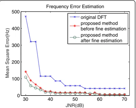
MSE (mean square error) of time delay and frequency change with JNR (jammer-to-noise ratio) are shown in Figs. 3 and 4, respectively. It can be seen from Fig. 3 that
30 40 50 60 70
frequency estimation error of original DFT is too large to reconstruct the DME signal exactly while the pro-posed method with tmwapDFT in this paper has a better performance. Frequency error after fine estimation has been further declined in lower JNR condition, while there is no distinct improvement after fine estimation with the JNR increasing because the error of tmwapDFT method is already very small. Time delay error before precise estimation is accurate enough to reconstruct the DME signal exactly. Nevertheless, more little errors can be attained after precise estimation which can make the DME interference mitigated to a lower level.
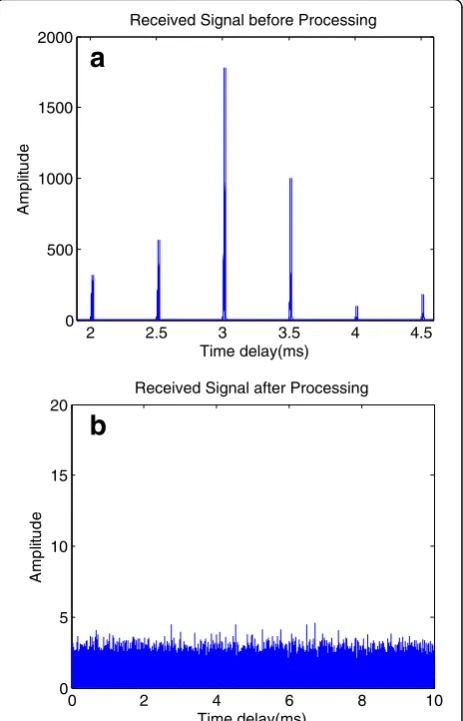
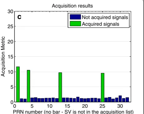
Six DME signals from different base stations are received in company with the four GPS signals sv1, sv4, sv13, and sv25 during the experiment. The JNRs are 50, 55, 65, 60, 40, and 45 dB, and the time delays are 2, 2.5, 3, 3.5, 4, and 4.5 ms, respectively. Being a kind of strong power signal, DME interference could lead to acquisition and tracking failure of a GPS receiver. The comparison results between the original signal and the suppressed signal with the proposed method are demonstrated in Fig. 5. Because GPS signal is totally buried under the noise level, the GPS spectrum should be the same as the noise spectrum. It can be seen that the DME interfer-ences are well mitigated after processing.
The acquisition results of different methods are given in Fig. 6. The pulse blanking method mitigates the interference by setting the signals which exceed the threshold to zero in time domain. Hence, it cannot thoroughly eliminate the bell-shaped interference pulse and lose a large part of useful GPS signal. The SNR of processed GPS signal is so low that the correlation peaks of acquisition are lower than the threshold and no GPS signals can be acquired. The hybrid method combines the pulse blanking method and notch filter
method together and preserves more useful signals, but the useful data missing problem still exists. Although the correlation peaks of acquisition are a little higher than pulse blanking method, the results still do not reach the threshold and the GPS signals cannot be ac-quired as well. The proposed method has prevailed per-formance and easily acquires the signal compared with the two traditional methods. It is slightly worse than GPS only circumstance because the proposed method can almost entirely maintain useful signals after interfer-ence suppression. In other words, the proposed algo-rithm has higher SNR and can achieve a better performance than other approaches.
5 Conclusions
The traditional DME interference suppression methods which bring about the loss of GPS signal will suffer from serious performance degradation of the GPS receiver. In this paper, a new DME interference suppression method
30 40 50 60 70
Time Delay Error Estimation
JNR(dB)
Fig. 4Time delay error changes with JNR
2 2.5 3 3.5 4 4.5
Received Signal before Processing
Time delay(ms)
Received Signal after Processing
Time delay(ms)
for GPS L5 signal is proposed, when the DME interfer-ences come from more than one base station. Firstly, fre-quency is estimated with tmwapDFT (time-modulated windowed all-phase DFT). Then, we use the estimated frequency to get amplitude and signal delay information with signal separation estimation theory. In order to fur-ther improve the estimation accuracy, a two-dimension fine estimation method is proposed, which takes the previous estimated results as the initial values. Experi-ment results show that the proposed method could esti-mate the parameters precisely, by which DME signal can be reconstructed and eliminated. It can be shown from the experiment results that the proposed method which keeps more useful satellite data has a better per-formance compared with conventional ones.
Acknowledgements
The work of this paper is supported by the Project of the National Natural Science Foundation of China (Grant nos. 61172112, 61179064, and 61271404), Science and Technology Fund of Civil Aviation Administration of China (Grant no. MHRD0606), and the Fundamental Research Funds for the Central Universities (Grant no. ZXH2009A003).
Authors’contributions
JL addressed the new method, carried out the anti-jamming studies and drafted the manuscript. RW conceived of the study. YH participated in its design and coordination. XW participated in the design of the study and performed the statistical analysis. YW participated in the design of the study. AZ participated in the sequence alignment. All authors read and approved the final manuscript.
Competing interests
The authors declare that they have no competing interests.
0 5 10 15 20 25 30
PRN number (no bar - SV is not in the acquisition list)
cir
Signal with DME interference mitigated by proposedmethod
0 5 10 15 20 25 30
PRN number (no bar - SV is not in the acquisition list)
cir
PRN number (no bar - SV is not in the acquisition list)
cir
Signal with DME interference mitigated by pulse blanking method
0 5 10 15 20 25 30
PRN number (no bar - SV is not in the acquisition list)
cir
Signal with DME interference mitigated by hybrid method
Not acquired signals
Author details
1Zhonghuan Information College Tianjin University of Technology, Tianjin,
China.2Tianjin Key Lab for Advanced Signal Processing, Civil Aviation
University of China, Tianjin, China.
Received: 2 June 2016 Accepted: 20 September 2016
References
1. A Steingass, A Hornbostel, H Denks, Airborne measurements of DME interferers at the European hotspot,Proceedings of the Fourth European Conference on Antennas and Propagation (EuCAP), 2010, pp.1-9, 12-16. 2. C Hegarty, T Kim et al.,Methodology for determining compatibility of GPS L5
with existing systems and preliminary results(Proceedings of the Institute of Navigation Annual Meeting, Cambridge, 1999)
3. W Fang, R Wu, D Lu, W Wang, A new interference suppression method in GPS based on modified GAPES. Sig. Process27(12), 1860–1864 (2011) 4. M Angelis, R Fantacci, S Menci, C Rinaldi,Analysis of air traffic control systems
interference impact on Galileo aeronautics receivers, (IEEE International Radar Conference, 2005), pp.585-595.
5. G Gao,DME/TACAN Interference and its mitigation in L5/E5 bands, (the ION conference on Global Navigation Satellite Systems, 2007)
6. S Brandes, U Epple, et al.Physical layer specification of the L-band Digital Aeronautical Communications System (L-DACS1), (Integrated Communications, Navigation and Surveillance Conference, 2009), pp. 1-12
7. J Grabowski,Characterization of L5 receiver performance using digital pulse blanking, (the ION conference, 2002)
8. Q Zhang, Y Zheng, SG Wilson, JR Fisher, R Bradley, Excision of distance measuring equipment interference from radio astronomy signals. Astron. J129, 2933–2939 (2005)
9. E Anyaegbu, G Brodin, J Cooper, E Aguado, S Boussakta, An integrated pulsed interference mitigation for GNSS receivers. J. Navig61, 239–255 (2008) 10. W Fang, R Wu, W Wang, D Lu, DME pulse interference suppression based
on NLS for GPS. Int. Conf. Sig. Process1, 174–178 (2012)
11. MG Christensen, SH Jensen, New results on perceptual distortion minimization and nonlinear least-squares frequency estimation. IEEE Trans. Audio. Speech. Lang. Process19(7), 2239–2244 (2011)
12. J Li, RB Wu, An efficient algorithm for time delay estimation. IEEE Trans. Sig. Process46(8), 2231–2235 (1998)
13. AV Oppenheim, RW Schafer,Discrete-time signal processing, upper saddle river, (Englewood Cliffs: Prentice Hall, 3nd Edition, 2010), pp.793-840.
14. XD Huang, ZH Wang, Principle of all-phase DFT restraining spectral leakage and the application in correcting spectrum. J. Tianjin Univ40(7), 882–886 (2007) 15. JZ Liu,Multidimensional all phase digital filtering theory and image multiscale
geometric representation, (Ph. D. dissertation, 2001), pp.23-28
Submit your manuscript to a
journal and benefi t from:
7 Convenient online submission
7 Rigorous peer review
7 Immediate publication on acceptance
7 Open access: articles freely available online
7 High visibility within the fi eld
7 Retaining the copyright to your article