23rd Australasian Conference on the Mechanics of Structures and Materials (ACMSM23) Byron Bay, Australia, 9-12 December 2014, S.T. Smith (Ed.)
EFFECT OF BEAM-COLUMN JOINT STIFFNESS ON THE DESIGN OF
BEAMS
Wahid Ferdous*
Centre of Excellence in Engineered Fibre Composite (CEEFC), School of Civil Engineering and Surveying, University of Southern Queensland Toowoomba, QLD, 4350, Australia. [email protected] (Corresponding Author)
ABSTRACT
The infrastructure should be design in such a way that ensures safe, serviceable, durable and economic construction. For the beam design, the joints between beam and column is traditionally considered a rigid connection which actually not fully rigid and therefore accounted an extra moment leading to structural over-design and subsequently higher cost of beam construction. This paper proposed a theoretical model for moment and deflection considering the actual stiffness of beam-column joint rather than traditional concept of rigid connection. A concentrated moving load is applied on the beam with three different support conditions such as fixed both end, simply supported and propped cantilever. This proposed model is then verified theoretically considering known boundary conditions. Results showed that the proposed theoretical model for moment and deflection of beam perfectly captured the existing beam equations with that specific support conditions and the cost of the beam construction can be reduced due to considering the actual beam-column joint stiffness.
KEYWORDS
Semi rigid joint, rotational stiffness, moment, deflection
INTRODUCTION
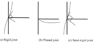
[image:1.595.209.405.603.693.2]Traditionally, the connections between beam and column in a structure is assuming either fully rigid or pinned which is not the actual behaviour according to the previous investigations (Johnson and Hope-Gill 1972; Cabrero and Bayo 2005). Rigid joints does not allow any rotations between the connected members while pinned joints are characterised by the free rotational movement between the connected elements and prevents the transmission of bending moments. The intermediate behaviour which is non-zero and non-infinite stiffness is called semi-rigid (Jaspart 2000). Figure 1 illustrated the classification of joints according to their rotational stiffness.
Figure 1. Different joints according to rotational stiffness (Jaspart 2000)
connection stiffness has a considerable impact on the load-displacement behaviour of the structure and the considerations of semi rigid connection in building frame can reduce the beam size, the overall building height and cladding costs (Barnard 1970). This approach is not only advantageous in terms of material savings but also providing a lateral stiffness for sway frames and these advantage may even increase if the joints are designed as semi rigid in both major and minor axis of the column (Gil et al. 2013).
In 2005, Cabrero and Bayo (Cabrero and Bayo 2005) proposed a design method for semi-rigid joints incorporating the design examples for demonstrating the applicability of the proposed method. Their study concluded that the semi-rigid design is the most cost effective solution when it is compared with the traditional pinned and rigid joints. In order to obtain the optimal design, the rotational stiffness and moment resistance is required to analyse (Simões 1996). Among the various methods (empirical, analytical, mechanical, numerical and experimental) of establishing moment-rotation curves for semi rigid joints, the so-called mechanical component method is the most commonly used method in practice. It estimates the properties of the materials and joints and allows calculating the rotational stiffness and moment resistance of the joint (Faella et al. 1999). Although the joint behaviour through experimental test can provide the most accurate knowledge, but this technique is too expensive in everyday design practice and is usually reserved for research purposes only (Díaz et al. 2011). Due to the lack of appropriate design methods, models and tools for joint rotational stiffness, this study focused on the theoretical model for moment and deflection in case of semi rigid joint.
THEORETICAL MODEL FOR BENDING MOMENT
In contrast with the traditional concept of rigid connection between beams and columns, this study considers a partial rigid joint between them. The stiffness of the joint is the function of bending moment and deflection of the beam. The analytical model is developed for the moment and deflection considering a moving point load ( ) on the beam as shown in Figure 2. Considering the joint-stiffness and in the support point „a‟ and „b‟ respectively, the slope of the beam at two supports can be presented by the definition of stiffness.
and
where and are the corresponding bending moments at two supports. The tangent of slope can also be calculated by
and
From the above correlations and using area-moment theorem,
[
( ) ̅̅̅̅] (1a)
[
( ) ̅̅̅̅] (1b)
where, is the flexural rigidity of the beam. Solving Eqs. (1a) and (1b)
( )
(2a)
( )
(2b)
Eqs. (2a) and (2b) represents the general equations for moment at point „a‟ and „b‟ respectively where the factors and mainly depends on the stiffness of joint, beam stiffness and the location of the load.
( ) ( ) ( )
( ) ( )
(3a)
( ) ( ) ( )
( ) ( )
(3b)
where,
Support stiffness ratio, (4a)
Beam to support stiffness ratio,
( )
(4b)
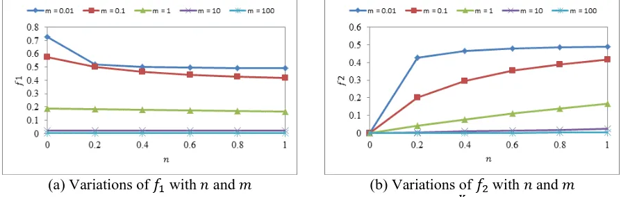
For centre point loading, the variations of and with and has been plotted in Figure 3. The beam to support stiffness ratio ( ) has been considered from 0.01 to 100 which indicates the support stiffness is ranged from 100 to 1/100 times of beam stiffness.
[image:3.595.82.529.591.733.2]For the identical support stiffness ( = 1) and a very small value of „ ‟ which is basically the rigid support condition, the factors and are both 0.5. Putting the magnitude in equation 2(a) and 2(b), the rigid end moment can be obtained.
THEORETICAL MODEL FOR DEFLECTION
Location of the Maximum Deflection
Before developing the theoretical model for the magnitude of maximum deflection, it is important to model the location of maximum deflection ( ). By definition,
(5a)
Since the maximum deflection occurs at point „c‟ (Figure 2) and therefore, . The area-moment theorem can also be used for determining as below.
( ) (5b)
Substituting the values of and and equating Eqs. (5a) and (5b), the location of maximum deflection can be determined from the quadratic Eq. (6).
√( )
(6)
The coefficient of , and in Eq. (6) can be determined from the following equations depending on the point of load application and the location of the maximum deflection.
if, if,
( ) ( ) ( )
( ) [ ( ) ]
( ) [( ) ( )] ( ) [( ) ( )]
Magnitude of Maximum Deflection
Theoretically the slope at the point of maximum deflection is zero (Figure 2) indicating
( ) ̅̅̅̅ (7)
when,
*
( ) ( )+ [
( ) ( ) ( ) [ ( )]] (8a)
Eq. (8a) can be rearranged as below
* ( ) ( )+ [ ( ) ( ) ( ) [ ( )]] (8b)
when,
[
( ) * ( ) ( ) ( ) ( ) ( ) ( ) ( ) +]
[
( ) ( ) ( ) [ ( ) ( )]]
[ ( ) * ( ) ( ) ( ) ( ) ( ) ( ) ( ) +]
[ ( ) ( ) ( ) [ ( ) ( )]]
(9b) Eqs. (8a) and (9a) presents the general equations for maximum deflection. The first part of those equations indicates the deflection of the beam due to simply supported action and the second part indicates the reduction of deflection due to semi rigid action. This can simplify as below.
(10)
where,
= deflection due to simply supported action = reduction of deflection due to semi rigid action
VALIDATION OF THE MODEL
The theoretical model proposed in this study has been validated using three known support conditions (Figure 4) and they are (a) rigid support, (b) simply support and (c) propped cantilever condition. The moment and deflection in the aforementioned condition is well established. The proposed model is validated using the necessary boundary conditions.
[image:5.595.86.530.345.435.2] [image:5.595.74.538.464.682.2](a) Rigid support (b) Simply support (c) Propped cantilever Figure 4. Different support conditions with centre point loading
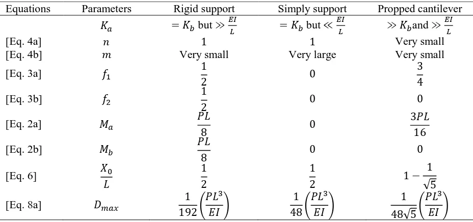
Table 1. Moment and deflection calculation for the known condition
Equations Parameters Rigid support Simply support Propped cantilever
but but and
[Eq. 4a] Very small
[Eq. 4b] Very small Very large Very small
[Eq. 3a]
[Eq. 3b]
[Eq. 2a]
[Eq. 2b]
[Eq. 6]
√
[Eq. 8a]
(
) (
) √ (
)
CONCLUSIONS
This study provides a theoretical model for moment and deflection incorporating the rotational support stiffness from which the following conclusions are drawn:
1. The theoretical model for moment and deflection can explain the intermediate behaviour of pinned and rigid joint condition and can easily introduce in everyday design practice.
2. The semi rigid joint between beam and column provides a lower moment at the end of the beam when it is compared with fully rigid joint. This lower design moment can reduce the required section modulus of the beam and subsequently a potential cost savings may achieve. 3. The results obtained from the model for the specific boundary conditions comply with the
well-known equations of simple mechanics.
FUTURE RECOMMENDATIONS
A basic approach has taken to establish the fundamentals of beam-column joint stiffness from which the further research could continue on the following areas:
1. Experimental investigation on the behaviour of beam when it is semi-rigidly connected with column.
2. Further research need to establish the theoretical model for semi-rigidly connected continuous beam.
ACKNOWLEDGMENTS
The author gratefully acknowledges the financial and technical support of the University of Southern Queensland.
REFERENCES
Barnard, P.R. (1970) “Innovations of composite floor systems” Canadian Structural Engineering Conference: Canadian steel industries construction council, pp. 13-21
Cabrero, J.M. and Bayo, E. (2005) “Development of practical design methods for steel structures with semi-rigid connections”, Engineering Structures, Vol. 27, pp. 1125-1137
Díaz, C., Martí, P., Victoria, M. and Querin, O.M. (2011) “Review on the modelling of joint behaviour in steel frames”, Journal of Constructional Steel Research, Vol. 67, pp. 741-758
Faella, C., Piluso, V. and Rizzano, G. (1999) Structural steel semirigid connections: theory, design and software, CRC Press
Fathelbab, F.A. (1987) The effect of joints on the stability of shallow single layer lattice domes, Doctor of Philosophy Dissertation, The University of Cambridge, UK
Gil, B., Goñi, R. and Bayo, E. (2013) “Experimental and numerical validation of a new design for three-dimensional semi-rigid composite joints”, Engineering Structures, Vol. 48, pp. 55-69 Jaspart, J.P. (2000) “General report: session on connections”, Journal of Constructional Steel
Research, Vol. 55, pp. 69-89
Johnson, R.P. and Hope-Gill, M. (1972) “Semi-rigid joints in composite frames” International Association for Bridge and Structural Engineering, pp. 133-144
See, T. (1983) Large displacement elastic buckling space structures, Doctor of Philosophy Dissertation, The University of Cambridge, UK