Int. J. Electrochem. Sci., 8 (2013) 10772 - 10787
International Journal of
ELECTROCHEMICAL
SCIENCE
www.electrochemsci.org
Performance Analysis and Multi-Objective Optimization of an
Irreversible Solid Oxide Fuel Cell-Stirling Heat Engine Hybrid
System
Liwei Chen1, Songhua Gao1, and Houcheng Zhang2,*
1
Mechanic and Electronic Engineering College, Sanming University 365000, Fujian Province, China.
2
Department of Physics, Ningbo University, Ningbo 315211, Zhejiang Province, China
*
E-mail: [email protected]
Received: 8 May 2013 / Accepted: 30 June 2013 / Published: 1 August 2013
A new hybrid system consists of a solid oxide fuel cell (SOFC) and a Stirling heat engine is established, where the heat engine is driven by high-quality waste heat generated in the SOFC. Based on the electrochemistry and non-equilibrium thermodynamics, analytical expressions for the efficiency and power output of the hybrid system are derived by taking various irreversible losses into account. The curves of the equivalent efficiency and power output varying with the electric current density are represented through numerical calculations. It shows that the performance of the solid oxide fuel cell can be greatly enhanced by coupling a Stirling heat engine to further convert the waste heat for power generation. The general performance characteristics of the hybrid system are revealed and the optimal regions of some important performance parameters are determined. By employing the multi-objective optimization method, the optimal operating regions are further divided into more detailed based on the priorities of the engineer. Moreover, it is pointed out that the investigation method in the present paper is valid for some other similar energy conversion and electrochemistry systems as well.
Keywords: Solid oxide fuel cell, Stirling heat engine, Hybrid system, Performance analysis, Multi-objective optimization
1. INTRODUCTION
conversion but also to reduce the harmful emissions of energy conversion processes. A fuel cell is a device that can efficiently and cleanly converts the chemical energy from a fuel into electricity through a chemical reaction with oxygen or other oxidizing agents. In 1839, the first fuel cell was invented by Welsh Physicist William Grove [1]. The first commercial use of fuel cells was in NASA space programs to generate power for probes, satellites and space capsules. Since then, fuel cells have been used in many other applications. Fuel cells are used for primary and backup power for commercial, industrial and residential buildings and in remote or inaccessible areas, because of their high conversion efficiencies and low environmental impact. [2-15].
There are many types of fuel cells, such as proton exchange membrane fuel cells (PEM), alkaline fuel cells (AFC), solid oxide fuel cells (SOFC), and so on [2]. Among them, SOFC is made entirely of solid materials, which is not limited to the flat plane configuration of other types of fuel cells and is often designed as rolled tubes [8], and it has been one of the most promising fuel cells due to its fuel flexibility and high efficiency. The high temperatures operating characteristics (800 to 1000 °C) [9, 11, 15] provide the possibility of cogeneration with other types of power generators such as gas turbines [10] or heat engines [13] for further power generation. Thus, it is a task deserving deeply investigation on how to availably utilize the waste heat produced in SOFC.
In the present paper, we will construct a hybrid system composed of a SOFC and a Stirling heat engine, in which not only the irreversible losses in the SOFC but also the heat-leak from the fuel cell to the environment as well as heat transfer between the fuel cell and the heat engine are considered. Based on the thermodynamic-electrochemical analysis, new expressions for some key parameters of the hybrid system such as efficiency and power output are derived. By using numerical calculations, the general performance characteristics are revealed and the the optimal regions for some important performance parameters are given. As a consequence, the performance characteristics of the hybrid system are optimized.
2. AN IRREVERSIBLE MODEL OF THE FUEL CELL-HEAT ENGINE HYBRID SYSTEM
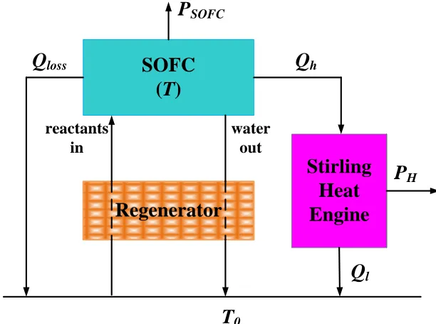
Figure 1 shows the configuration of a SOFC-Stirling heat engine power generation system, which mainly consists of a SOFC, a Stirling engine and a regenerator. The SOFC in the hybrid system plays a role of the high-temperature heat reservoir of a Stirling engine for a further use of the waste heat. The regenerator acts as a counter-flow heat exchanger, which economically absorbs the heat in the high-temperature exhaust gas to preheat the reactants to attain the reaction temperature.
In order to analyze the performance of the whole hybrid system, the following major assumptions are often adopted [16-20]:
(1) Both the SOFC and the Stirling engine are operated under steady-state condition; (2) The regenerator is regarded as a perfect one;
(4) All gases involved are assumed to be compressible ideal gases;
(5) Completed chemical reactions are considered and no reactants are remained after the reactions.
Q
lossSOFC
(
T
)
Regenerator
T
0reactants in
water out
P
SOFCStirling
Heat
Engine
Q
hP
H [image:3.596.142.448.154.381.2]Q
lFigure 1. The schematic diagram of an irreversible SOFC-Stirling heat engine hybrid system. With the help of these assumptions, the expressions of the system performance can be investigated. Below, we will analyze each component in the hybrid system respectively and then study the performance of the whole hybrid system.
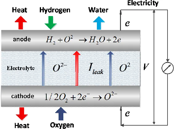
Figure 2. Principle of a solid oxide fuel cell.
By using hydrogen as fuel and air as oxidant [19, 20], the basic principle of an SOFC is illustrated in Figure 2. At the cathode, oxygen is reduced by the incoming electrons to oxygen anions that are conducted through the electrolyte to the anode where they electrochemically combine with the adsorbed hydrogen to form water and heat as a by-product and release electrons to the external circuit. The overall reaction in such a fuel cell can be summarized as H21/ 2O2 H O Heat2 Electricity.
In order to quantificationally describe the electrochemical reactions in the SOFC, it is quite important to understand the thermodynamic principles of the fuel cell operation. The basic thermodynamic relationship can be given as
H Q G T S
(1)
The total energy H Q is divided into two parts, which are electrical and thermal components. As long as the enthalpy change is more negative than the Gibbs free energy change of the reaction, a part of the total energy, which cannot be converted to electrical energy, is released as heat. The enthalpy change and Gibbs free energy change between the products and the reactants of the global electrochemical reaction at temperature T for the steady-state fuel cell can be, respectively, expressed as [16, 19, 21-23]
( ) e j ( ) ( )
e k
k j
k j e
d n
d n iA
H h T h T h T
dt dt n F
(2)and
( ) e j ( ) ( , )
e k
k j
k j e
d n
d n iA
G T T g T p
dt dt n F
where k k j j
k j
h h h
, ( , ) k k( , ) j j( , )k j
g T p T p T p
, n is the number of moles, his the molar enthalpy of the species at temperature T, p is the partial pressure of the species, is the partial molar Gibbs free energy of species, and subscripts k and j represent the kth product and the
jth reactant of the reaction, respectively.
Since the Gibbs free energy change of an electrochemical reaction is a measure of maximum electrical energy obtainable as work from the reaction, the maximum power output generated by the reaction in the fuel cell can be determined by
r
Pev ( , )
e
iA
G g T p
n F
(4)
In practice, this part of energy is never completely utilized because of the various thermodynamic and electrochemical irreversibilities [16, 21, 22]. When the fuel cell works normally and produce useful power through the external load, the total entropy production rate can be determined by [19, 20]
2 2
int int/ 0 / 0
tot leak leak
S I R T I R T (5)
where T0 is the ambient temperature, Iint is the electric current through the equivalent internal
resistance Rint, and the Ileak is the electric current through the leakage resistance Rleak. Here the rate of entropy production, Stot, is that of the fuel cell system and environment together and it is never negative.
By considering all the irreversibilities, the power output and the efficiency of fuel cell can be deduced as [19, 20]
2 0 1 cell tot e iA k
P G T S m m
n F RTd
(6)
and 2 1 1 cell cell P k m m
H h RTd
(7)
where 2 2 2 1/2 0 1
( ) ln( H O )
H O
p p
m g T RT RTd
p
,k Rint /Rleak, and
1 1
1
0, 0, 0 , ,
2 sinh ( ) 2 sinh ( ) exp( ) ln(1 ) ln(1 )
2 2
e el el
e e
a c L a L c
in L F E
i i i i
d n n
i i R RT i i
.
2.2. A Stirling heat engine
respectively. Its main advantages are that the cycle may be driven by a wide variety of fuels, and it offers the opportunity for high efficiency power generation [24-26]. The Stirling cycle has been seriously considered for a variety of uses. For example, Stirling engines driven by fuel cell may be used in mobile applications. Generally, the analyses about the optimal match of the fuel cell and the heat engine may be a key issue for any hybrid system [27].
1
T
2
T
0
T
T
1
V
V
21
Q
2
Q
P
V
[image:6.596.166.425.190.405.2]0
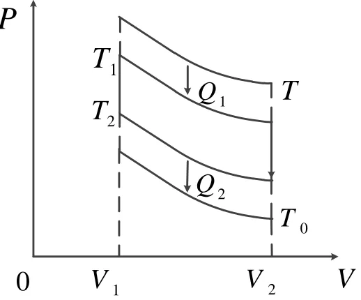
Figure 3. PV-diagram of a Stirling heat engine.
For a practical Stirling heat engine, there are invariably thermal resistances between the working substance and the external heat reservoirs. Hence, we will use a powerful tool which is finite-time thermodynamics. The results obtained here have more realistic instructive significance for the optimal design of real fuel cell-driven systems than those derived from traditional equilibrium thermodynamics.
The amounts of heat Q1 and Q2 absorbed from the heat reservoir at temperature T and released to the heat source at temperature T0 per cycle may be written as [24]
1 1( 1)1
Q k TT t (8) and
2 2( 2 0)2
Q k T T t (9)
respectively, where k1 and k2 are the thermal conductances between the working substance and the heat reservoirs at temperatures T (the temperature of exhaust gas) and T0 (ambient temperature), t1 and t2 are the times spent on the two isothermal branches at temperatures T1 and T2, respectively.
1 2
( )
Q xC T T
(10)
where x is the fractional deviation from ideal regeneration, when x0 the Stirling cycle operators with ideal (complete) regeneration, C is the heat capacity of the working substance per mole partaking in the regenerative processes. For the convenience of analysis, it is assumed that the time spent on the regenerative branches is proportional to that of the isothermal branches, i.e.
1 2
( )
re
t b t t (11)
where b is a constant. The average rate of heat supply can be expanded as
1 1 1 2
1 2 1 1 1 2 2 2
( )
(1 ) / ( ) / ( )
h h
re h c
Q T m T T
q
t t t b T k T T T k T T
, (12)
where m1xC/
Rln(V2/V1)
, R is the universal gas constant. For a qh, the maximum efficiency of the Stirling engine can be attained is given by [24]
1 1 0
1 1 1 1 0
/ ( 1)
2 / ( 1)
h e
engine
h e
q K m T m T T
m T m q K m T m T T
, (13)
where
0.5 2
1 1 0 1 1 0
( 1) / 4 ( 1)
e h
T m T m T q K m m TT , 1
2
1 2
(1 )(1 / )
k K
b k k
.
As illustrated in Figure 2, a part of the waste heat produced in the fuel cell is directly released as heat-leak to the environment, and the amount of the heat can be given by [6, 27, 28]
0
( )
loss l
Q A TT (16)
where is the convective heat-leak coefficient, and Al denotes the effective heat-transfer area. Combining the previous analysis, the rate of waste heat from SOFC to the Stirling heat engine is given by
0
( )
h cell loss cell l
q H P Q H P A TT (17)
By substituting Eq. (17) into Eq. (13), the optimum efficiency and power output of the Stirling heat engine may be expressed as
1 1 0 2 3 0
1 1 1 1 0 2 3 0
( 1) (1 ) ( )
2 ( 1) (1 ) ( )
cell e
engine
cell e
m T m T im m T T T
m T m m T m T im m T T T
(18)
and
2 3 0
1 1 0 2 3 0
1 1 1 1 0 2 3 0
(1 ) ( )
( 1) (1 ) ( )
2 ( 1) (1 ) ( )
engine cell
h cell e
cell e
P K im m T T
m T m T im m T T T
m T m m T m T im m T T T
(19)
where 2
e
A
m h
n FK
and 3 Al
m K
.
As illustrated in Figure 1, the regenerator working as a heat exchanger in the hybrid system, heats the inlet reactants from the ambient temperature to the cell temperature by using the high temperature outlet gas of the fuel cell. For the sake of simplicity, the regeneration process is assumed to be ideal. This assumption is reasonable, because the efficiency of regenerators with the values of 98–99% have already been reported [12, 13, 29-31]. With the help of perfect regeneration, the fuel cell and hence the whole hybrid system can be ensured to work normally and continually under the condition of steady-state.
2.4. The efficiency and power output of the hybrid system
Using equations (6), (7), (18) and (19), one may obtain the efficiency and the power output of the entire SOFC-Stirling engine hybrid system, i.e.,
3 0 21 1 0 2 3 0
1 1 1 1 0 2 3 0
1 ( )
( 1) (1 ) ( )
2 ( 1) (1 ) ( )
hybrid cell engine hybrid
all
cell cell
cell e
cell e
P P P
Q H
m
T T im
m T m T im m T T T
m T m m T m T im m T T T
(20) and
3 0 21 1 0 2 3 0
1 1 1 1 0 2 3 0
1 ( )
( 1) (1 ) ( )
2 ( 1) (1 ) ( )
hybrid cell engine
cell cell
e cell e
cell e
P P P
m
T T im
iA h
n F m T m T im m T T T
m T m m T m T im m T T T
(21)
It is seen from equations (20) and (21) that the efficiency and the power output of hybrid system are closely dependent on the irreversible losses including the irreversibilities within the fuel cell itself and originating from the heat transfer between the SOFC and Stirling heat engine. In the next section, the general performance characteristics and the optimal criteria of the hybrid system will be given.
3. GENERAL PERFORMANCE CHARACTERISTICS AND OPTIMAL CRITERIA
1
m , m2 and m3. It is necessary to point out the physical significance of the three parameters m1, m2 and m3. m1 is a parameter to measure the irreversibility of finite-rate heat transfer in the heat engine. The parameter m2 is a colligation measurement for the systemic structure, which may be mainly used to discuss the influence of the irreversible heat transfer between the heat engine and the fuel cell [20]. The parameter m3 is used to discuss the influence of the heat-leak irreversibility from the fuel cell to the surroundings. In the following calculation, the parameters m1 0.004 , m2 0.03 KA m-1 2 ,
3 0.002
m
Table 1. Operating conditions and performance-related parameters.
Parameter Value
Operating pressure, p0(atm) 1
Fuel composition, 2
H
P ; PHfuelO
2 (atm) 0.97; 0.03
Air composition, 2
O
P (atm); PHO
2 (atm) 0.21;0.79
Number of electrons, ne 2
Pre-factor for anode exchange current density, a(A m-2) 5.5 10 8
Activation energy of anode, Eact a, (J mol-1) 5
1.0 10
Pre-factor for cathode exchange current density, c(A m-2) 7.0 10 8
Activation energy of cathode, Eact c, (J mol-1) 5
1.2 10
Electrolyte thickness, Lel (μm) 20
Activation energy of O2, Eel (J mol-1) 8.0 10 4
Pre-factor of O2, 0 (S m-1) 3.6 10 7
Ratio of the internal resistance to the leakage resistance, k 1/100
Anode limiting current density, iL a, (A m-2) 4
2.99 10
Cathode limiting current density, iL c, (A m-2) 4
2.16 10
Faraday constant, F (C mol-1) 96485
Universal gas constant, R (J mol-1 K-1) 8314
Table 2. Molar enthalpy change and Gibbs free energy change values at p0 1atm of the hydrogen-oxygen reaction for different temperatures.
Teperature(K) T=1073K T=1123K T=1173K T=1223K T=1273K
h
g
(J/mol) -188680 -185900 -183100 -180280 -177460
are chosen. Below, numerical calculations are carried out to quantitatively investigate the influence of these parameters on the performance of the hybrid system. The results are based on the parameters summarized in Table 1 and Table 2, and these parameters are kept constant unless mentioned specifically. The fuel composition is taken as 97% H23% H O2 , and the typical oxygen composition in the ambient air, i.e., 21% O279%N2, is used as oxidant.
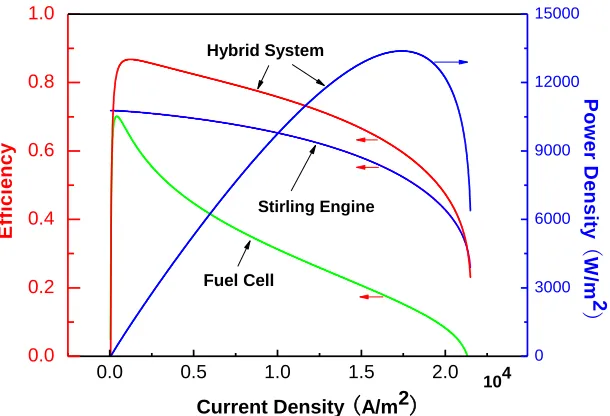
By using Eqs. (20) and (21), the efficiency and power density of the hybrid system operating at different current density are presented in Figure 4, where the separate efficiencies in the hybrid system are given and P* P/A. It can be clearly seen from Figure 4 that the efficiency and power density of the hybrid system first increase then decrease as the current density increases. The values of the efficiency of the single system are lower than that of the hybrid system. Through the way of coupling system, the utilization rate of energy can be greatly improved. In addition, there exist a maximum power density Pmax* and a maximum efficiency max, which will be made a detailed discussion in the following. Figure 5 shows the efficiency versus the power density at different operating temperatures, where Pm* and m are the power density at the maximum efficiency max and the efficiency at the maximum power output Pmax, respectively. According to Figure 5, one can obtain the optimally operating regions, which has a negative slope in the part of the *
~
P curve. When the hybrid system operates in this region, the efficiency will decrease as the power density increase, and vice versa. Thus, the optimal ranges of the efficiency and power density should be given as
max m
(22) and
* * *
m max
P P P (23)
The above results show that Pm*, m, Pmax* and max are the four important parameters which are related to a set of thermodynamic and electrochemical parameters. *
m
P and m determine the allowable optimum values of the lower bounds of the power density and efficiency, while Pmax* and
max
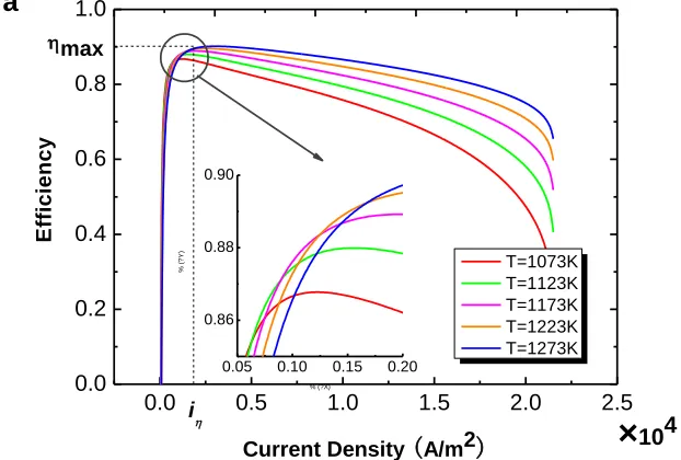
determine the upper bounds. It is significant to note that the four important parameters closely depend on the thermodynamic and electrochemical parameters of the hybrid system and can be calculated numerically for the given values of other parameters. According to Eqs. (20) and (21), one can further generate the curves of efficiency and power density varying with current density for different temperatures, as shown in Figure 6, where i and iP* are, respectively, the current densities at the maximum efficiency max and the maximum power density *
max
P . Figure 7 can also explain the optimal region of the current density
*
P
i i i (24)
and iiP* are not optimal from the thermodynamic point of view although the hybrid system may work in these regions. Thus, i and iP* are, respectively, the upper and lower bounds of the optimized current density. Specifically, the maximum efficiency max and the maximum power density *
max
P will increase when T is increased, accordingly, the optimal current density i and iP* will also be changed. In the practical operation of the hybrid system, engineers should choose some reasonable parameters in order to improve the system performance.
0.0 0.5 1.0 1.5 2.0
0.0 0.2 0.4 0.6 0.8 1.0
Current Density (A/m2)
E
ff
ic
ie
n
c
y
104
0 3000 6000 9000 12000 15000
P
o
w
e
r
D
e
n
s
it
y
(
W
/m
2
)
Hybrid System
Stirling Engine
[image:11.596.147.452.207.415.2]Fuel Cell
Figure 4. The curves of the efficiency and the power density varying with the current density, where the power density Phybrid* Phybrid /A.
0 4000 8000 12000 16000 20000
0.0 0.2 0.4 0.6 0.8 1.0
T = 1273 K
T = 1173 K
m
P*m
E
ff
ic
ie
n
c
y
Power Density (W/m2)
max
P*max
Figure 5. The curves of the efficiency varying with the power density for different temperatures, where max and Pmax* are, respectively, the maximum efficiency and power density of hybrid system.
Thus, how to give a consideration to both the efficiency and the power output in the optimal region will become an important problem in practical optimum design and operation. For this reason, we may introduce a multi-objective function which is defined as the product of the efficiency with a weighting factor and power output [4], i.e.,
Z P (25)
where is a weighting factor, whose value is determined by the engineer’s requirements for the power output and the efficiency. In other words, the multi-objective function is a concrete value of the hybrid system, and 0 .
0.0 0.5 1.0 1.5 2.0 2.5 0.0
0.2 0.4 0.6 0.8 1.0
0.05 0.10 0.15 0.20 0.86
0.88 0.90
×
104T=1073K T=1123K T=1173K T=1223K T=1273K
E
ff
ic
ie
n
c
y
Current Density (A/m2)
max
i a
%
(?
Y
)
[image:12.596.146.457.262.472.2]
0.0 0.5 1.0 1.5 2.0 2.5 0 4000 8000 12000 16000 20000 24000 ×104 P o w e r D e n s it y ( W /m 2 )
Current Density (A/m2)
[image:13.596.142.458.95.310.2]T=1073K T=1123K T=1173K T=1223K T=1273K iP* P* max b
Figure 6. The curves of (a) efficiency and (b) power density varying with current density for different temperatures, where i and iP* are, respectively, the current density at the maximum efficiency
max
and the maximum power density Pmax* .
0.0 0.5 1.0 1.5 2.0 2.5
0.0 0.2 0.4 0.6 0.8 1.0 P*max
max
i
iP*
Current Density (A/m2)
0 3000 6000 9000 12000 15000
104
Z*1,max P o w e r D e n s ity ( W /m 2 ), Z * (W /m 2 ) E ff ic ie n c y iZ*1,max
Figure 7. The curves of the efficiency, power density, and Z* varying with the current density, where
* /
Z Z A, * 1
Z
[image:13.596.131.467.379.607.2]
0 3000 6000 9000 12000 15000
0.0 0.2 0.4 0.6 0.8 1.0
P*max
max
Power Density (W/m2)
E
ff
ic
ie
n
c
y
P*Z1,max
D0 1<<
0<<1
z1,max m
P*m
D1
D
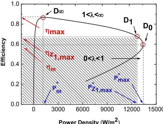
Figure 8. The *
P curve used to expound the physical meaning of the multi-objective function, where
1,max
Z
and
1
* ,max
Z
P are, respectively, the efficiency and power density corresponding to
* 1,max
Z .
If one focus more on the efficiency than power output, the weighting factor can be let as
1 . When , the multi-objective function may be rewritten as a new form, i.e.
1/ 1/
Z P , which is efficiency. If one takes more attention to the power output, the weighting factor can be let as 0 1. When 0, the multi-objective function may become one objective function, i.e., Z0 P. If engineer gives the same attention to the power output and the efficiency, the weighting factor can be chosen as 1, which has been shown in Figure 7.
In order to discuss the choice problem of the optimal current density, we will mark some divided points in Figure 8, which illustrates more clearly how to select the optimal operating region, using Eqs. (20), (21) and (25). Where D0, D1 and D on the curve correspond to the state that Z* attains its maximum when 0, 1 and . Point D represents any point on the ~P* curve between D0 and D . The horizontal and vertical coordinates corresponding to D may form a rectangle, whose area is equal to *
Z. In Figure 8, the area of the shaded part is Z1,max* .
[image:14.596.150.435.92.309.2]
1,max
Z
i
i
i
(26)1,max
max Z
(27) and
1,max
* * *
m Z
P P P (28)
If more attention is paid on the power output than on the efficiency, i.e. start-up for SOFC hybrid vehicles [33], the optimal operation regions of the parameters mentioned above are, respectively, determined by
*
1,max
Z P
i i i (29)
1,max m
Z
(30) and
1,max
* * *
max
Z
P P P . (31)
4. CONCLUSIONS
The importance of present paper lies in a new cycle model which can describe the general characteristic of SOFC-Stirling heat engine hybrid system. The various irreversible thermodynamic and electrochemical losses are described. The maximum efficiency, power output and the optimal operating region are determined to improve the whole system performance through numerical simulations. The problem how to give consideration to the efficiency and power output in the optimal region of the current density is discussed in detail. The results obtained here may provide some theoretical basis for the optimal design and operation of practical SOFC-Stirling heat engine. This method may be easily extended to other fuel cell hybrid system to develop irreversible models suitable for the optimal energy-management strategies of fuel cell hybrids.
ACKNOWLEDGEMENTS
This work was supported by the Natural Science Foundation of Fujian Province (No. 2012J01016), Foundation of Zhejiang Educational Commission (Y201326937), and Natural Science Foundation of Sanming University (No. B201202/G), People’s Republic of China.
References
1. S.C. Singhal, K. Kendal, High Temperature Solid Oxide Fuel Cell: Fundamentals Design and Applications, Elsevier Ltd., Oxford, 2003.
2. http://en.wikipedia.org/wiki/Fuel_cell
4. G. Nahar, K. Kendall, Fuel Processing Technology 92 (2011) 1345.
5. H. Zhang, J. Wang, S. Su, J. Chen, Int. J. Hydrogen Energy 3 8 (2013) 9609. 6. S.H. Chan, H.K. Ho, Y. Tian, Int. J. Hydrogen Energy 28 (2003) 889.
7. M. Ghasemi, M. Ismail, S. K. Kamarudin, K. Saeedfar, etc., Applied Energy 102 (2013) 1050. 8. W.J. Yang, S.K. Park, T.S. Kima, J.H. Kimb, etc., J. Power Sources, 160 (2006) 462.
9. C. Haynes,J. Power Sources, 92 (2001) 199.
Y. Zhao, N. Shah, N. Brandon, J. Power Sources, 10 (2010) 181. 10. Hill, Michael. Ceramic Industry, September 1, 2005.
11. Y. Zhao, J. Chen, J. Power Sources, 186 (2009) 96.
12. Y. Zhao, C. Ou, J. Chen, Int. J. hydrogen energy 33 (2008) 4161.
13. 0M.S. Ismail, K.J. Hughes, D.B. Ingham, L. Ma, M. Pourkashanian, Applied Energy 95 (2012) 50. 14. Stambouli, A. Boudghene. Renewable and Sustainable Energy Reviews, 6(2002) 433.
15. D.A. Noren, M.A. Hoffman, J. Power Sources 152 (2005) 175. 16. S.T. Ro, J.L. Sohn, J. Power Sources 167 (2007) 295.
17. Y. Qi, B. Huang, K.T. Chuang, J. Power Sources 150 (2005) 32. 18. Y. Zhao, C. Ou, J. Chen, Int. J. Hydrogen Energy 33 (2008) 4161. 19. Yingru Zhao, Jincan Chen, Journal of Power Sources 186 (2009) 96. 20. F. Calise, A. Palombo, L. Vanoli, J. Power Sources 158 (2006) 225. 21. S.J.Watowich, R.S. Berry, J. Phys. Chem. 90 (1986) 4624.
22. C.Wang, M.H.Nehrir, S.R. Shaw, IEEE Trans. Energy Convers. 20 (2005) 442. 23. J. Chen, Z. Yan, L. Chen, B. Andresen, Int. J. Energy Res., 22, (1998) 805.
24. M. W. Zemansky, (1968). Heat and thermodynamics, 5th edn, McGraw-Hill, New York. 25. Ayres, R. U. and R. P. Mckenna, Alternatives to the Internal Combustion Engines, The Johns
Hopkins University Press, Baltimore, MD. 1972.
26. D. Sanchez, A. Mu˜noz, T. Sanchez, J. Power Sources 169 (2007) 25. 27. P.G. Bavarsad, Int. J. Hydrogen Energy 32 (2007) 4591.
28. D.A. Blank, G.W. Davis, C.Wu, Energy 19 (1994) 125.
29. S. Bhattacharyya, D.A. Blank, Int. J. Energy Res. 24 (2000) 539. 30. D.A. Blanka, J. Appl. Phys. 84 (1998) 2385.
31. H.Y. Kwak, H.S. Lee, J.Y. Jung, J.S. Jeon, D.R. Park, Fuel 83(2004)2087. 32. M. De Francesco, E. Arato, J. Power Sources 108(2002)41.