Abstract— This paper is concerned with the power quality and efficiency the power system. The system is being complex day by day so there is a need of an automated system to control and supervise the substation. In projected work the substation is modelled with a microcontroller and a GSM module that improves the quality of power transfer and reduces the no. of outages. A platform is used to display the various calculated parameters like voltage, frequency, current, phase angle. All these parameters are sent by a SMS as the system comprises of a GSM module which is interfaced with a microcontroller. The sensors placed at the substation senses the situation and then send related signals to the connected microcontroller. All the mentioned parameters are equated to their pre-defined values in a continuous way to provide protection. Under faulty conditions the unit gets shut down by the employed relays. An alert message can be sent in this situation for indication. Thus, the work is increasing the efficiency of substation in an intelligent manner.
Index Terms— Microcontroller, GSM Module, Transformer, ADC, Substation.
I. INTRODUCTION
The supervision of substation is necessary for improving the power quality. In power system there is a large distance between the generation and load so the quality of power transmission at a large distance gets affected. Previously the quality was not concerned much but now-a-days it is more concerned as the load in the system is increasing continuously[1][2]. A large amount of power gets lost while transmitting the power that results in reduced quality of power reached at the substations. To overcome this problem we need to consider the reasons behind the poor quality of the power, and then find the solutions[3].Also the consideration of monitoring, protection, and control of the system. Poor power quality is major constraint in the power system and it may lead to instability of the system. There is a need to develop a system that monitors, supervises, and provides controls and also detects and classifies the existing constrains. Bad quality of power would affect various appliances connected to the power system like dimming of light or equipment failure. For proper working of equipment all the constraints should be within specific limit. Power surges, sags, transients are various power quality problems. The power system suffers from power outages, collapse, blackouts because of lack in automation in the system. WNS gives the overview by taking data from various sub-systems
Revised Manuscript Received on September 10, 2019.
Bagyalaxmi Behera, Dept. of Electronics & Communication Engineering, Siksha O Anusandhan Deemed to be University, Odisha, India.
(E-mail:[email protected])
Mihir Narayan Mohanty, Dept. of Electronics & Communication Engineering, Siksha O Anusandhan Deemed to be University, Odisha, India.
present in a grid. The main objectives are to improve power quality of the system, maintain continues supply power, and to provide supervision.
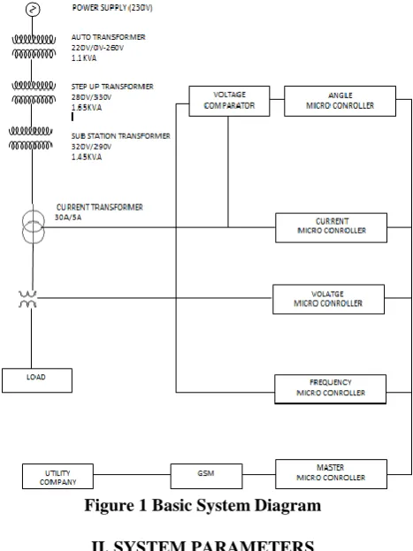
First section of the paper includes microcontroller that receives different parameters at different time interval wherein the time-interval is loaded in the microcontroller. The parameters go to the microcontroller from transformer and to the transformer from sensor. A register in microcontroller is used for storing parameters. Current and voltage values are then compared with a reference value which is pre-defined.
[image:1.595.317.551.351.663.2]The second section comprises of an Analog to Digital Converter (ADC). The third section consists of a GSM receiver for receiving output to related user on mobile[4]. A digital display can also be used to display output
Figure 1 Basic System Diagram II. SYSTEM PARAMETERS
The obtained parameters out of transformer are calculated by the programmed microcontroller are given below:-
a) Calculation of Voltage:
The concept which is used in the project is the calculation of voltage by connecting a resistor of very large value in
Supervision and Control of Substation by using
GSM Module and Microcontroller
parallel to the load. A transformer of rating 300/5V is employed which is specifically a potential transformer. The output or secondary voltage of the transformer is applied to a potential divider which is made up of various registers of one ohm and two ohm connected in series. The maximum analog voltage that can be applied to the microcontroller is 5 volts so a potential divider is employed before the microcontroller for maintain voltage at 5V. If voltage applied to the microcontroller is more than 5V then it would burn out. This concept is used for over voltage faults. The ohmic value of resistor is so chosen to make a potential divider by making an allowance for the maximum voltage across secondary of transformer during over voltages.
An algorithm of peak detection is used that takes corresponding voltage because of actual current at load or the voltage value at line and then change it into digital form with the help of inherent analog to digital converter.
The programming carries the samples of rate. The calculation, storing and comparison of samples are now taken into account in a continuous way. One by one samples are taken and compared with the existing values, and the programming goes on only when the value which is measured is greater than the existing value. A formula for the calculation of current and voltage is given by:
2
Peak
RMS
(1)Refer Figure 3 for simulation.
b) Current Calculations:
A current sensor resistance is employed for the measurement of current. The ohmic value of the sensing resistor chosen 0.3 ohms and power is twenty five watts. The load is connected in series to the resistance. Initially, the value of voltage across the resistance is calculated and
then measured value of voltage goes to the controller. This is transformed into digital form from analog to digital converter. The converted value is passed by the controller to the actual current of the circuit. But the use of such current sensor resistance is not practical. So, we go through a current window transformer whose rating is 30 amps/5 amps. A flawless sinusoidal waveform is formed by coupling a resistance across the secondary side of c/r transformer. The value of resistance connected depends on the burden, after all the calculations a resistance of value 0.6 ohms and 25 watts is employed across the current transformer, in this way current value would be measured precisely specially when the load is greater than the value one amps.
The load that have been chosen for the project is eight Incandescent type bulb with rating of 100watts.
2 bulbs are turned on simultaneously. The value of the current shown on screen of LCD is likened to the value of current calculated with the help of a clamp meter. Now, load is amplified by turning on 2 more additional bulbs and analyses is considered with comparison then the procedure is repetitive. The analyses found is quite precise for the loads that triggered a current near four amps to move from the circuit. Another secondary load called “burden” which is different from the load whose measurements are taken and calculated by the formula:
P=I*(I*R) (2)
Wherein, the value of P is fifteen watts and value of current taken is five amps, so by the formula we get the
value of resistance ohms i.e.
ohm
6
.
0
)
5
(
15
2
, and its
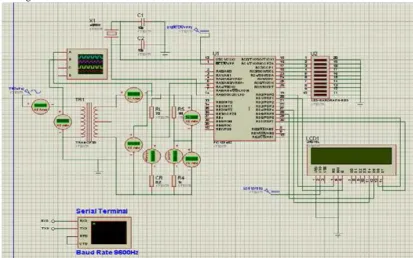
[image:2.595.94.508.465.723.2]simulation is shown in Figure 3.
Figure 3 Simulation of current calculations, Current transformer is preceded by a current resistance. c) Calculations Related to Frequency:
An inherent timer for determining the value of frequency is present in the microcontroller. The microcontroller carries 3 timers and all perform with accuracy. The microcontroller works as a counter to calculate its number of pulse input for frequency calculation. The applied input signal is in the form of sinusoid waveform and the output is in digital form followed by the ADC converter. The digital form of frequency should be equal the value of applied frequency value. An operational amplifier measures the frequency but it cannot be used for great voltages (high voltages). So, this difficulty can be solved in 2 ways:
I. First one is employing a voltage comparator across the secondary side of the potential transformer. This would limit the voltage of secondary side to five volts ;and
II. Other one is employing an operational amplifier via a voltage buffer on primary side of the potential transformer. The primary high voltage side is being isolated from low voltage side with the help of the voltage buffer. For
providing isolation a photo-coupler is used.
The voltage buffer not only used for the above mentioned operation it also converts the input into a square wave output, if the output is one then it means the voltage output is five volts. The buffer can also be used at substations because of low secondary voltage value than RMS 5000V compatibly. PIC18F452 is to measure the applied frequency value by the count of square waveforms and
d) Angle Calculation:
Angle is measured by measuring the time of ‘0’crossing between the current signal and voltage signal. The combination of operational amplifier and voltage comparator converts a sinusoidal input waves into a unidirectional output square wave and then it is applies to a inbuilt AND gate which performs AND operation on it. The non-inverting end of the operational amplifier is supplied
with the voltage of secondary side of transformer while the inverting end is kept grounded. Secondary voltage of transformer is equated with the value of zero volts which is the inverting end voltage. The analyzed output is bidirectional in nature with the one as logic magnitude and similar to the supplied voltage of operational amplifier. The diode converts the bidirectional output into unidirectional form. The diode which is used for the conversion is specifically a germanium diode. The resultant signal is of current and voltage in square waveform. After the subtraction of time (ON time for both current and voltage waves) from the time of reach a phase angle ninety degrees resulting in time of parting of ‘0’crossing of two current and voltage waves. The angle is calculated
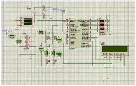
Figure 4 Simulation for frequency calculations, 50 HZ value of frequency input to the transformer and microcontroller.
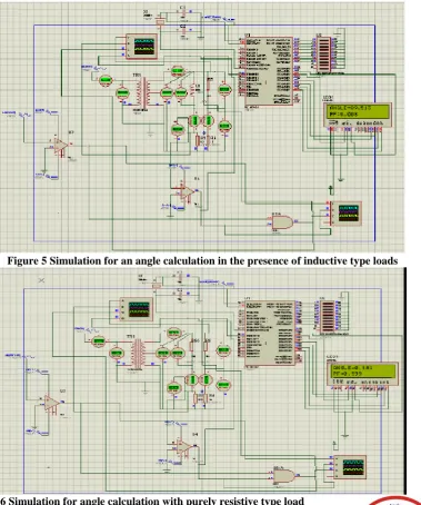
Figure 5 Simulation for an angle calculation in the presence of inductive type loads
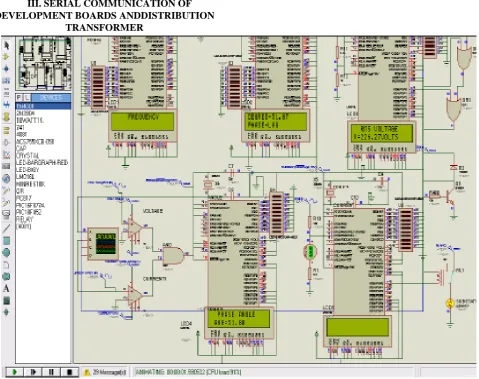
III. SERIAL COMMUNICATION OF DEVELOPMENT BOARDS ANDDISTRIBUTION
[image:5.595.64.544.65.444.2]TRANSFORMER
Figure 7 Simulation for serial communication When the burden on microcontroller increases then the
effectiveness as well as preciseness of the microcontroller reduces, so we require more development boards to overcome these problems. Calculations of voltage and current needs timers, analog to digital converter, frequency measurements, phase angle calculations, and counters. There is one master board which is connected to 4 other sub-boards after determining all the above mentioned parameters.
The main master board is interlinked with a GSM module. There is a serial communication between 4 board and a master board. In this the values of active, reactive power, phase angle, current value and voltage value are calculated on the bases of received frequency and phases.
There are 2 types of serial communications: One is synchronous; and
Another is Asynchronous.
Figure 8 Simulation in case of lagging loads A numeric relay is used for protecting transformer and to
eliminate problems like over vtgs, under vtgs, over and under frequency etc. The relay operates under faulty situations when the values of parameters increases above the
specific values. The microcontroller senses the condition and then an associated port will be activated, further this port sends a signal to relay for performing its operation.
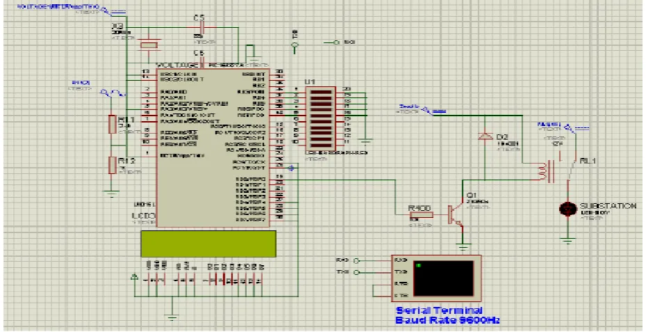
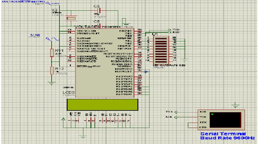
[image:6.595.70.535.471.709.2]IV. GSM MODULE FOR SENDING MESSAGES & RESULTS
The circuitry which is used for interfacing the main master development board and GSM module is:
Serial communication circuitry
The signals have an electrical is ‘RS232’ which PC serial-ports always use. Different from typical TTL logic in which
five volts is equivalent to the logic one and zero volts is equivalent to logic zero, RS232 shows minus twelve volts equivalent to logic one and plus twelve is equivalent to logic zero. Longer communication can achieved by this.
Transceiver is used for the circuits which uses RS232 module.
[image:7.595.79.529.150.399.2]It converts plus-minus twelve volts to a range of zero to five and performs inversion of voltages[5].
Figure 10 GSM Module Simulation
V. CONCLUSION
The projected work is similar to power line communication which is used as a communication board for a smart grid system. By the designed project we can achieve an automated system which is economical and reliable in nature. It has improved the quality and efficiency of system. In the project control and supervision of a substation is done by interfacing of microcontroller and GSM at inexpensive price and a numeric relay is employed to perform its function for various faults. The project delivers 2-way integration, the substation can contact to tell about type of fault to a utility company. So, the projected paper is capable to supervise and control the substation remotely.
VI. REFERENCES
1.Siemens, “Siemens Energy Sector: Power Engineering Guide,” 2014.
2.N. Mungkung, N. Gomurut, T. Tanitteerapan, S. Arunrungrusmi, W. Chaokumnerd, and T. Yuji, “Analysis of technical loss in distribution line system,” 8th WSEAS Int. Conf. Telecommun. Informatics Anal., 2009.
3.J. Pathak, Y. Li, V. Honavar, and J. McCalley, “A Service-Oriented Architecture for Electric Power Transmission System Asset Management,” 2007.
4.F. Valdes-Perez and R. Pallas-Areny, “PIC Microcontrollers,” in Microcontrollers, 2010.
5.J. Rigelsford, “GSM Networks: Protocols, Terminology and Implementation,” Sens. Rev., 2014.
6.W. L. Chan, A. T. P. So, and L. L. Lai, “Internet based
Syst., 1999.
7. -S. -Tenbohlen, “Benefit of sensors for on-line monitoring systems for power transformers,” Rev. l’Electricité
l’Electronique, 2008.
8. T. Leibfried, “Online monitors keep transformers in service,” IEEE Comput. Appl. Power, 1998.
9. A.-R. Al-Ali, A. Khaliq, and M. Arshad, “GSM-based distribution transformer monitoring system,” 2004. 10. M. Wang, A. J. Vandermaar, and K. D. Srivastava,