Abstract: In this paper, we have discussed and summarized the techniques of radar cross section reduction (RCSR). RCSR has been prompted due to the evolution of military technology. The paper reviews the basic concepts and characteristics of metamaterials, as these are the most favorable development that impacts defense industry products and stealth technology. This paper emphasizes the role of airpower and the ever-increasing demand for stealth. Initially, the blending of the fundamental aspects of stealth technology through radar signatures and methods of signature reduction are discussed. Then, the description of metamaterials and detailed analysis of their properties is made. This paper review the fundamental properties of metamaterials. It also explores the recent research activities on metamaterials in various areas. Some existing researches techniques used for RCSR are examined. The metamaterials are engineered media whose electromagnetic responses are different from those of their constituent components. The general benefits of metamaterials are pointed out in the paper. Metamaterials are mostly used in antenna configuration for enhancing antenna performance such as realizing miniaturization, expanding the operating band, enhancing gain as well as reducing RCS. These characteristics of the metamaterials are basically the reason why metamaterials should be used in stealth technology. The various categories of metamaterials used for RCSR are studied in the paper. In this paper, we have also proposed a unit cell. The unit cell consists of a square loop and intersecting strips at the edges of add shaped structure.
Index Terms: Electromagnetic bandgap, Metamaterials, Microstrip Antenna, RCS, RCSR.
I. INTRODUCTION
Significant research attentiveness in radar cross section reduction (RCSR) has been prompted due to the evolution of military electronic technology. In order to avoid detection by radars, radar cross section (RCS) of key military targets should be reduced [1]. Antenna makes a significant offering to overall RCS due to its key function which is to receive and radiate electromagnetic energy. Nuclear weapons are possessed by a large number of countries, but the number of countries that have the ability to make stealth military vehicles is quite low. The possibility of any country using a nuclear weapon is very less because of the extreme international pressure. Therefore in tactical warfare owning nuclear weapons is not of much significance.
Stealth technology is a part of military tactics [2]-[4]. The main notion of stealth is to work/operate without giving
Revised Manuscript Received on July 09, 2019.
Manbir Kaur, ECE, Thapar Institute of Engineering and Technology, Patiala, India.
Rajesh Khanna, ECE, Thapar Institute of Engineering and Technology, Patiala, India.
Atipriya Sharma, ECE, Thapar Institute of Engineering and Technology, Patiala, India.
enemy forces any indications of its presence [3]. This technique was first explored by blending into the background visual clutter. It covers active and passive electronic countermeasures which include a range of techniques used with ships, aircraft, submarines, satellites to make them invisible to various detection devices like radar, infrared, sonar[6],[7]. For these parts of the electromagnetic spectrum, it corresponds to military camouflage. The extent of threat lead to selection of amount of stealth that has to be embedded in any particular design [8]. In most of the cases, especially in case of war devices, the key requirement is low RCS so that the device can be hidden from the rival’s radar [9]. RCS of any device be it airborne or naval ship depends on its shape and material. RCSR has been a matter of interest from the past numerous years. Microstrip antennas are quite favored in microwave dominion especially in aircraft systems. RCSR of microstrip antenna is an important research part of a stealth object [10].
Microstrip antennas are widely used for military applications due to their properties like the lightweight, low profile and ease of fabrication [5],[11]. These antennas are most commonly used in array configurations. The microstrip patch antenna ground plane has higher radar cross section and until now many methods have been devised for reduction of RCS of microstrip patch antenna [10],[11]. High efficiency and composite absorbing structures allow a large portion of incidental energy to be scattered or attenuated in the insignificant direction in order to minimize monostatic scattering, but antenna due to its characteristics could not be coated with any broadband absorbing material while continuing to operate. Due to these reasons RCS reduction while maintaining electrical visibility is difficult.
In this paper researches on RCSR using metamaterials are reviewed and summarized. This paper is organized as follows. In Section II, the literature review of RCSR using metamaterials is studied. In Section III, radar concepts and RCSR techniques are discussed. In Section IV, the various categories of metamaterials are reviewed. In Section V, a unit cell of metamaterial is proposed. In Section VI, the paper conclusion is presented
.
II. LITERATURE SURVEY
A. Literature Review of RCSR using Metamaterials Ying Liu et.al [12] proposed a novel method to minimize RCS along with preserving
radiation characteristics of the antenna. This is achieved by using the principle of
Radar Cross Section Reduction Techniques
using Metamaterials
passive cancellation along with Polarization conversion metamaterial (PCM). Results show in-band RCS is reduced 16 dB in comparison to the reference antenna. In addition to this out -band RCS has been reduced by 14dB.
Yuping Shang et.al [13] proposed a microstrip patch antenna with the reduced value of RCS. This reduction is achieved by switching the reference antenna ground plane with a complex ground plane consisting of band stop frequency selective surfaces (FSS) unit cells.
Mohsen Zahir Joozdani et.al[14] investigated RCSR of 2x2 patch antenna array using a miniaturized square loop, which was part of bandstop FSS. Stopband of FSS was identical with the resonant frequency band of the antenna which is from 3.3-3.4 GHz. Miniaturized FSS replace ground plane of reference antenna excluding the region below patch. FSS behaves as a ground plane for stop band other than this region it is transparent. The wideband RCSR is achieved in 4-9.5 GHz range.
Jeremiah P. Turpin et.al [15] proposed a technique of replacing ground plane of reference antenna with absorbing FSS with the intention of reducing RCS at higher frequencies. This approach is advantageous than many other techniques used for RCSR as these techniques degrade the antenna performance.
Ying Liu et.al [16] investigated a low RCS microstrip antenna. The basis of design is microstrip resonator and implementation of FSS out of RCSR can be achieved by replacing metal ground with FSS ground. In-band RCSR can be achieved by loading of microstrip resonator. Majority of the RCSR is achieved in the frequency range of 3-10 GHz. Out of band and In band RCSR achieved is around 17 and 13 dB respectively.
Hao Jiang et.al [17] proposed an antenna with partially reflecting surface (PRS) and high gain for out of the band and in band RCSR. In-band RCS is achieved by using a metamaterial ground plane. PRS is situated about one-half wavelength higher than metamaterial ground plane (MGP) in order to increase antenna directivity out of band reduction is attained by using absorbing material. A significant RCSR has been achieved in the frequency range 8-17 GHz.
Ali Azarbar et.al [18] proposed a technique using composite artificial magnetic conductor (AMC) surface with a magnetodielectric substrate for broadband reduction of RCS. The advantage of using magneto-dielectric is that it increases in phase reflection bandwidth of AMC structure. The composite surface constitutes two types of AMC cell where each AMC cell operate at a different frequency. The phase differences are tuned to be closed such that reflections from cells cancel out each other. The results show that RCSR more than 13 dB was achieved with a 93% bandwidth.
M. Mighani et.al [19] proposed a novel wideband chess board surface along with a double layer in order to reduce RCS. By using a novel structure of two AMC cells we can achieve -10 dB RCSR over 73% of frequency bandwidth. Boards with higher thickness are required to increase bandwidth in case of chessboard structure.
Yunqi Fu et.al [20] proposed the usage of composite AMC surface for wideband RCSR. The composite surface constitutes two AMC cells, with AMC cells having a different resonant frequency. The phase difference between AMC cells
is required to be in a range close to 6π, due to this reflection from AMC cells cancel out each other.
Yongtao Jia et.al [21] presented a broadband mushroom antenna with high gain to attain wideband RCSR. In-band RCS can be largely reduced as the mushroom structure resonates at antennas operating frequency. For out of band RCSR metal ground is being replaced by bandstop FSS. In order to add zero degree reflection phase square metallic patches are printed periodically below the cells of FSS. This aids the RCSR
.
III. RADAR CONCEPTS
A. Radar Signatures
Radio Detecting and Ranging is a device used to detect, locate, track, and identify objects at considerable distances. It operates by transmitting radio waves towards the objects and observing the echoes returned from them.
The various categories of radars used and their operating range as met by an aircraft as it enters a hostile region [22] is depicted as 1. Lower frequency range (0.1-1.0 GHz) is used for surveillance and detection (VHF, UHF, S-Band) 2.Medium frequency range is used for tracking the target, used mostly by SAM launchers (C, X) 3.Higher frequency range is used by radar onboard aircraft (Ku, K, Ka).
Tab. I IEEE Radar letter-band nomenclature [23].
BAND DESIGNA
TION
NOMINAL FREQUENCY(M
Hz)
BAND DESIGNATI
ON
NOMINAL FREQUEN
CY(GHz)
HF 3 – 30 X 8 – 12
VHF 30 – 300 Ku 12 – 18
UHF 300 – 1000 K 18 – 27
L 1000 – 2000 KA 27 – 40
S 2000 – 4000 V 40 – 75
C 4000 – 8000 Mm 100 – 300
B. RCS of an Aircraft
RCS is interpreted as the area of an imaginary perfect reflector that would reflect the same amount of energy back to the receiving radar antenna, as reflected by the actual target. According to the IEEE dictionary, RCS is represented as an estimate of the reflective strength of a target. It is represented as 4π times the ratio of the power per unit solid angle scattered in a specific direction, to the power per unit area of a plane wave incident on the scatterer from a specific direction, and is given as[24],
RCS = (1)
r = radar range, = scattered power density (w/ ), =
power density intercepted by target (w/ ). RCS is an approximation of observability of a target, which in turn is dependent on its EM properties and external features. The RCS emphasizes on the electromagnetic energy of the receiver that is reflected from the target to the incident electromagnetic energy. When electromagnetic waves are incident on a body, some part
reckoned by the phenomena of reflection and diffraction. The RCS of an object is an approximate dimension of the target as seen by the radar which in turn is used for detection of objects. RCS can be represented as a coherent summation of contributions from numerous scattering centers of the target which were once illuminated by the radar.
Multiple or sequential reflections may be caused by some part of the reflected signal that may be in the direction of other conducting surfaces, the resultant RCS is computed as the vectorial sum of all these returns. The superposition of individual echoes in addition to the highly specular return from the various flat surfaces and retro-reflectors cause widely varying echo amplitude with a small change in the view angle (termed as scintillation). The RCS of an object is dependent on [25]
1. Shape of target 2. Size of target
3. The ratio of the target dimension, to the wavelength of the impinging radar wave.
C. Radar Detection Range
The maximum range of the radar depends upon its operating frequency. Radar waves with lower frequency are less attenuated in propagation. The antenna size required can be impractical if the frequency is too low. For precisely tracking the targets, tracking radars require good accuracy and necessary. Because of these anti-aircraft gun systems and guided missiles operate at a high frequency. The range of the monostatic radar is given as [26],
(2)
For radar, the maximum detection range alters as a function of the fourth root of the target’s RCS. So attaining reduction in the detection range of threat radar leads to a significant reduction in the aircraft RCS. For example, to reduce the detection range by half, RCS has to be decreased 16 times.
D. RCS Reduction Techniques
An aircraft has to use several RCSR techniques simultaneously in order to reduce RCS by a significant amount. The number and type of RCSR techniques used depend on several factors like cost, mission effectiveness, mission profile, etc. The key difference between the active and passive techniques of RCSR is that active techniques work by destructive interference of the incoming wave with the scattered field within the array while in passive techniques, a difference of amplitude and phase of the scattered wave from one part of the target cancels the same from the other part. The platform is made ‘invisible’ to the probing radar sources by the active cancellation of the impinging waves.
Nowadays, the tremendous knowledge of passive RCSR techniques can be used for controlling the EM scattering. These passive reduction techniques mostly use either shaping [29] or applying RAM [27],[28]. The efficiency of such methods is dependent on the angle of incidence, frequency as well as the polarisation of the incident wave. For an aerial vehicle (missile or aircraft), stealth may be achieved by
considering angular region. The profile of the vehicle is designed so that only a small angular range is available to the radar. In addition to above-mentioned passive techniques, some other methods such as artificial magnetic conductors (AMC) [63], frequency selective surfaces (FSS)[53] and active RCSR [37],[38] have also been used for RCSR. The technique of RCSR using shaping is defined as follows
E. RCSR by Shaping
The overall size of ships, military vehicles or airplanes cannot be varied much, because of the confines of operational capabilities [29]. The geometric cross section of military vehicles cannot be easily reduced. The concept of shaping works by orienting the target edges and surfaces to achieve deflection of scattered energy in the direction away from the radar[30],[31]. Two approaches can be taken in the technique of shaping. The first approach is to replace flat surfaces with curved surfaces and this leads to the elimination of narrow but intense specular lobes. This increases the general echo levels at nearby aspect angles, although this reduces the magnitudes of specular echoes. The second approach is to extend flat and singly curved surfaces, even if this increases its intensity but it narrows the specular lobe. To confine specular flash to a narrow angular region it is preferred to maintain larger surfaces as smooth and flat as it is feasible. Larger is the area, higher will be maximum RCS, and faster it drops off.
A spherical surface independent of its orientation will reflect from any point. When the specular reflections are suppressed or eliminated then reflections from other directions become significant. The structures are shaped so as to reduce the corners, edges and surface discontinuities. The key motive is a redirection of the reflected waves in nonspecular directions, thereby reducing the backscattering. The shaping technique must satisfy the aerodynamic requirements of the military vehicle (e.g. aircraft, missiles, ships, etc.). Another technique of RCSR is radar absorbing material.
F. RCSR by Radar Absorbing Material (RAM)
The second technique of RCSR is the usage of RAM. As the name suggests, the function of the radar absorber is to soak up incident energy, hence reducing the scattered energy or energy reflected back to the radar. At radar frequencies, two primary approaches exist to reduce reflections from a structure: absorption and cancellation. Absorption is the process in which energy from the wave is transferred to the material as it passes through it [32]. Radar energy can be enwrapped through one or more of the loss mechanisms, which might be involving magnetic or dielectric properties of the material. The cause of loss of radar energy is due to the transformation of radio energy into heat energy. Majority of the absorbers do not dissipate a sufficient amount of energy so as to become detectably warm when they are irradiated by incident wave. The wave should be able to travel many wavelengths before being significantly attenuated.
RAM operates by enwrapping the incident EM energy and transforming it into heat
RAMs are quite efficient in controlling the backscattering than forwarding scattering. They have comparatively high values of the imaginary part of permeability and permittivity. Salisbury screen and Dallenbach layer are narrowband RAM coatings and have been used since the the 1950s [32]. Modern radar systems span over a wide range of frequencies. Hence a wideband RAM is needed. A typical RAM used in aircraft could be a composite or ferrite based paint [35],[36]. However, there are significant disadvantages to using RAM. Firstly, most of RAMs are toxic. Secondly, precise application techniques are required for RAM coatings, as it is necessary that the coating thickness and smoothness must be uniform across the platform. Both the passive approaches i.e. shaping and RAM are mostly considered simultaneously to obtain the acceptable low visibility over the operational frequency band. Two more RCSR techniques are active and passive cancellation.
G. RCSR by Active Cancellation
Active cancellation also known as active loading is more ambitious than passive loading. In this technique, the target emits the radiance in time coincidence with approaching pulse so that the amplitude and phase of emitted wave cancel those of the reflected wave. Inactive cancellation, the target emits a signal which copies the echo received by the radar provided that it is out of phase by one-half wavelength, so that as a result the radar receives no signal at all. The key benefit of this approach is that it uses quite a small amount of power and it provides no indication about the target's presence. The shortcoming of this approach is that it requires fast processing. A poorly executed process of active cancellation could make the target more visible to the radar. Active cancellation technique is most suitable for low-frequency RCSR. In this frequency range scattering patterns exhibit broader lobes and use of absorber and shaping become quite difficult. This technique of RCSR has been described to be used by the Rafale [37],[38] and has been implicitly rooted by Dassault [40], without providing any details [39].
H. RCSR by Passive Cancellation
In passive cancellation, the basic approach is to bring out an echo source whose phase and amplitude is adjusted so that it can cancel wave from another echo source. The target which consists of the scattering element is called the loaded body, as opposed to this the bare target is called the unloaded body. This technique is termed as impedance loading. This method is usually limited to a small spatial sector and is efficient over only a narrow frequency band [41].
IV. METAMATERIALS
In present years, metamaterials have drawn tremendous interest due to their unique electromagnetic properties. Metamaterials are mostly employed in antenna configuration for enhancing antenna performance such as realizing miniaturization, expanding the operating band, enhancing gain as well as attaining RCSR of antennas.
Metamaterials are the artificial materials with characteristics which may not be generally available in nature [42]. These metamaterials do not attain their characteristics from
composition but they are dependent on structure. These operate by using the involvement of small inhomogeneities to implement macroscopic behavior [43]-[45].
The metamaterials have become part of the mainstream of electromagnetics. The main characteristic of metamaterials is their desired and unusual qualities that exist due to their unique structure & design. In a composite media, the interaction of electromagnetic waves with the inclusions leads to the production of electric & magnetic moments. This will affect the macroscopic effective permeability and permittivity of the bulk composite medium. Metamaterials classification is as follows. Fig1 depicts the metamaterial classification.
A. Negative Index Metamaterial
Negative-index metamaterials (NIM) have a negative index of refraction due to negative values of both permeability and permittivity[46],[47]. This material can be termed as DNG(double negative materials). Some other keywords used for these metamaterials are "media with a negative refractive index" as well as "backward-wave media"[43].
B. Single Index Metamaterial
Metamaterials with chirality property are made of chiral materials which have non zero effective parameter k. The term left-handed refers to circularly polarized waves that constitute the propagating modes in case of chiral media. The term right-handed refers to the trio of the magnetic field, electric field and Poynting vector which exist in negative refractive index(NIM) media, which generally is not chiral[50],[51].
C. Bandgap Metamaterial
Electromagnetic band gap(EBG) metamaterial have the property of controlling light propagation. This property is implemented done with photonic crystals and left-handed materials. Photonic crystal has a property of prohibiting light propagation completely. Both categories can be designed with band gaps at desired frequencies and amount of light allowed to propagate in desired and specific directions[48],[49].
D. Chiral Metamaterial
Fig. 1 Metamaterial Classification[52]
E. Frequency Selective Surfaces (FSS)
FSS are periodic surfaces with similar two-dimensional arrays of elements organized on a dielectric substrate [53]. Based on the characteristics of the 2-D array, the incident plane wave will be either transmitted (passband) or it will be reflected back (stopband) and this will be either completely or partially. These conditions occur when the resonant frequency of FSS elements and frequency of electromagnetic (EM) wave are the same. So, an FSS hasthe capability of blocking or passing the electromagnetic waves of particular frequency ranges in the free space.
FSS is best known as a spatial filter. The properties of FSS elements like their shape, size as well as their periodicity lead to the resonance. FSS has been widely studied over the past five-six decades and a variety of optical and microwave FSS have been invented. Earlier these were mostly used in reflector antennas [54], involving antenna radomes as well as resonant beam splitters [55],[56].
In present times, the most prominent application of FSS is for reducing or controlling RCS or as antennas radomes. The design complications of FSS limit their performance, including unresponsiveness to the angle of incidence, the polarization of electromagnetic wave and requirement of compact size. Traditional FSS did not provide sufficient spatial filtering results and they were narrow band. Comprehensive research is ongoing to improve the FSS, efforts are made to miniaturize the frequency selective structure and enhance the frequency response along with broader bandwidth (BW) at higher angles of incidence. Single layered FSS experience unstable performance due to variation of electromagnetic wave angle of incidence, hence they have been proved inefficient. To overcome this limitation multi-layered FSS have come into existence. These provide the flexibility of changing parameters to attain the required performance. Fig 2 and 3 depict taxonomy of FSS and functionality of FSS. Fig 4 presents the various shapes of FSS elements.
Fig. 2 A taxonomy of FSS [57]
Various types of FSS exist such as 1. FSS on basis of Fractal elements
2. Active and Three-dimensional structure for microwave technology
3. Embedded structures consisting of inserted plates and metallic rods on the basis of the stepped-impedance resonator
4. Integrated structures
5. Electromagnetic bandgap structures 6. Metamaterial structures
Fig. 3 The functionality of an FSS [57]
[image:5.595.112.237.61.255.2]Fig. 4 Various shapes of FSS elements [53].
F. Electromagnetic Bandgap Structure (EBG)
The EBG operates by inhibiting propagation of the electromagnetic wave in particular band of frequencies termed as bandgap, which in turn depend upon its material parameters as well as its geometrical parameters, in contrary to this metamaterial show left-handed behavior opposing well-known phenomena of optics such as Doppler effects, etc.
The reflection phase characteristics are used to estimate the electromagnetic nature of any surface. The reflection phase refers to a PMC and a reflection phase denote a PEC surface. When a plane wave is an incident normally on a PEC surface, the total tangential E field should be zero to satisfy boundary conditions. The incident electric field and the reflected electric field must have the opposite signs, which lead to the value of reflection coefficient to be −1. The reflection phase in case of the perfect electric conductor is . Similarly, for a perfect magnetic conductor, the reflected electric field and the incident electric field should have the same sign but the reflected magnetic field and the incident magnetic field should have the opposite sign. For this case the reflection phase is and corresponding reflection coefficient value is equal to +1 [59]. In reality, the PMC surface do not actually exist in nature. EBG reflection phase range from + to - with an increase in frequency. The frequency range of + and − mostly coexist with a bandgap of the EBG structures. In-band RCS reduction is achieved by using EBG structure loaded with lumped resistances [60] and for out of band RCS reduction mushroom-like EBG structures are used [61],[62].
G. Artificial Magnetic Conductor (AMC)
Among all the metamaterial, AMC structures [63]-[72] are specifically used in designing of low-profile as well as highly efficient antennas [73]-[79]. AMC have inherited the in-phase reflection properties which in turn reduce the radiations meted out to the body [80] in wearable applications [80]-[82]. PMC does not actually exist in nature. AMC is synthesized PMC. From viewpoint of electromagnetics, AMC is dual to a PEC. AMC exhibit a phase value of 0◦ and a reflection coefficient value of 1 in the
ideal lossless case. AMC show characteristics of PMC over a particular frequency band. AMC operation bandwidth varies from + ◦ to − . For this range, the destructive interference between reflected and direct waves will not be caused by phase values. The main drawback in unilayer case is the narrow AMC operational bandwidth. By using a low relative dielectric permittivity substrate and optimizing the design of unit cell additional reduction in cost is attained In AMC structure every unit cell is represented as a distributed parallel LC network having one or more than one resonant frequencies. The resonant frequency is the frequency where AMC conditions exist and at this frequency impedance is high. For the parallel LC circuit, in-phase reflection bandwidth is proportional to √L/C and the resonant frequency is equal to 1/(2π√LC).In order to design an AMC structure with the required bandwidth and at a certain frequency, we have to change the unit cell’s geometry along with other changes like changing substrate’s relative dielectric permittivity a well as thickness.
Higher is the value of relative permittivity of dielectric substrate, lower will be the AMC bandwidth [68]. The change of unit cell geometry leads to modification in equivalent LC resonant circuit. In order to attain broader AMC operational bandwidth, the value of L is to be increased and that of C is to be reduced. To increase the value of L thick dielectric substrate can be used. Other means to increase L are by including long and narrow strips in geometry. Value of C can be increased by enhancing the gap between the unit cell metallization edges. Another method is by a reduction in the relative dielectric permittivity of the substrate. A trade-off solution involving and substrate thickness has to be adopted, so as to attain both compact size as well as broad AMC operation bandwidth.
The shaping technique used for RCSR is based on changing the surface or shape of the device under test (DUT) so as to redirect all the scattered energy away from the source. One technique of obtaining this scattering is by the usage of planar configuration. The planar structure that has shown the prospect of narrowband RCSR is based on using a combination of AMC and PEC in a chessboard-like configuration[34],[84],[85]. The principle of operation of the chessboard configuration consisting of AMC and PEC is based on the destructive interference between the waves reflected by these cells. At its working frequency, AMC cells lead to phase change of reflected wave whereas in case of PEC cells phase change of exist. Summing these two effects a net phase difference of is achieved between the radiations from the PEC and AMC cells which lead to destructive interference and hence attaining a null in the specific direction [83].
The major drawback of AMC and PEC chessboard configuration is its narrowband operation bandwidth structure. Outside the range of operation bandwidth, AMC act as PEC and destructive interference property does not hold. This shortcoming can be removed by replacing PEC cells in chessboard configuration by another AMC cell which operate at the different
condition of destructive interference to hold at least the resonant frequency of both AMC. As a result, a dual-band design may be constructed to overcome this gap.
V. DESIGN AND SIMULATED RESULTS OF UNIT CELL
In this paper, we demonstrated a unit cell of the metamaterial to achieve a reduction in RCS of an antenna. The front view of the unit cell is depicted in figure 5. Unit cell consists of a square loop and intersecting strips at the edges of add shaped structure. The unit cell of metamaterial is deposited on FR-4 substrate with 4.4 permittivities and loss tangent of 0.025, whereas the thickness of the substrate used is 2 mm. The copper employed for metamaterial structure has an electrical conductivity of 5.7 x S/m and thickness of copper is 0.035mm. The design variables for adopted metamaterial geometries with corresponding symbols are shown in Table II. The structure is designed, simulated and optimized using CST Microwave Studio software using floquet boundary conditions. To simulate the structure the unit cell boundaries in –x and in –y directions and open add space boundary in the z-direction has been chosen.
5(a)
[image:7.595.328.521.139.329.2]5(b)
Fig. 5 Proposed Unit cell (a) front view (b) side view
Tab. II Parameters of proposed unit cell
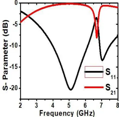
The simulated reflection and transmission characteristics of the unit cell under the normal incidence in the frequency
range from 2-8 GHz are shown in figure 6. It is seen that the designed unit cell exhibits a bandstop performance at the center frequency of 5 GHz. The peak reflection characteristic value of the unit cell is -20.24dB at 5.0 GHz. The bandwidth corresponding to -10 dB reflection characteristics for the unit cell is 2.2 GHz from 3.9 GHz to 6.1 GHz.
Fig. 6 Magnitude of S-parameters of the Unit cell under normal incidence
VI. CONCLUSION
In this paper, various types of metamaterials and their features have been discussed. Stealth technology is the key to achieve air superiority in present-day warfare. The most important requirement of defense industry worldwide in this century is to hide military units during war or when we manage an unexpected blow to the opponent. Metamaterials are the pillar of this conceal unit task. Paper presents a review of RCSR using metamaterial. The overview of various techniques and metamaterials used for RCSR is provided. Finally, a novel metamaterial structure is designed and simulated using CST Microwave Studio software, which can further be used for RCSR.
REFERENCES
[1] Y.Liu, S.X Gong, and H.B Zhang, “A Novel Fractal Slot Microstrip Antenna with Low RCS”, IEEE Antennas Propag.Soc.Int.Symp., pp 2603-2606, 2006
[2] C.B Wilsen, D.B Davidson, J.W.Odendaal, D.J Janse van Rensburg, “ The RCS Reduction of Microstrip Patch Antennas ”, in Proc. 10th
Int. Conf.Antennas Propag., pp 174-177, 1997
[3] D.Lynch, Introduction to RF Stealth, NC, USA, SciTech, 2004 [4] W.Xu, J.Wang, M.Chen, Z.Zhang, “RCS Reduction of Patch Array
Antenna with Composite Patch Structure for Reduction of In-Band RCS.”, IEEE Antennas Wireless.Propag.Lett., vol 14, pp 139-142, 2014
[5] Pozar, D.M., Schaubert, D.H., “Microstrip Antennas: The Analysis and Design of Microstrip Antennas and Arrays” Wiley, New York, 1995 [6] Rao G.A, Mahulikar S.P, “ Integrated review of stealth technology and
its role in airpower ”, Aeronautical Journal, vol 106, pp. 629-641, 2002
[7] Mahulikar S.P, Sonawane H.R , RaoG.A, “Infrared signatures studies of aerospace vehicles”, Progress in Aerospace Sciences, vol 43, pp. 218-245, 2007
[8] Ruan, Y., “Radar Cross Section and Stealth Technology”, National Defense Industry Press,
Beijing, 1998
[10] J. Ling, S.-X. Gong, P.-F. Zhang, H.-W. Yuan, B. Lu, and W.-T.Wang, “Method for
PARAMETER VALUE(mm) PARAMETER VALUE(mm)
L1 4.5 G1 0.7
L2 3.5 G2 0.3
L3 3 G3 0.25
L4 1.75 G4 1
RCS reduction of the microstrip patch antenna”, J .Xidian Un iv vol37, pp. 295–299, 2010
[11] W. Xu, J. Wang, M. Chen, Z. Zhang, and Z. Li, “A novel microstrip antenna with composite patch structure for reduction of in-band RCS,” IEEE Antennas Wireless. Propagation Letter., vol. 14, pp. 139–142, 2014
[12] Ying Liu, Yuwen Hao, Kun Li, and Shuxi Gong, “Radar Cross Section Reduction of a Microstrip Antenna Based on Polarization Conversion
Metamaterial”, IEEE Antennas and Wireless Propagation Letters,
pp80-83, vol. 15, 2016
[13]Yuping Shang, Shaoqiu Xiao, and Bing-Zhong Wang, “Radar Cross-Section Reduction Design for a Microstrip Antenna”, Microwave and Optical Technology Letters, pp1200-1204, vol. 56, no. 5, May 2014
[14] Mohsen Zahir Joozdani, Mohammad Khalaj Amirhosseini, and Ali Abdolali, “Wideband RCS Reduction of Patch Array Antenna with
Miniaturized FSS”, Microwave and Optical Technology Letters, pp
969-973, vol. 58, no. 4, April 2016
[15] Jeremiah P. Turpin, Peter E. Sieber and Douglas H. Werner,
“Absorbing Ground Planes for Reducing Planar Antenna Radar
Cross-Section Based on Frequency Selective Surfaces”, IEEE
Antennas and Wireless Propagation Letters, pp1456-1459, vol. 12, 2013
[16]Ying Liu, Yuwen Hao, Hui Wang, Kun Li, and Shuxi Gong, “Low
RCS Microstrip Patch Antenna Using Frequency-Selective Surface
and Microstrip Resonator”,IEEE Antennas and Wireless Propagation
Letters, pp1290-1293, vol. 14, 2015
[17] Hao Jiang, Zhenghui Xue, Weiming Li, Wu Ren, and Meng Cao,
“Low-RCS High-Gain Partially Reflecting Surface Antenna With
Metamaterial Ground Plane”,IEEE Transactions on Antennas and
Propagation, pp4127-4132, vol.64, no. 9, September 2016
[18] Ali Azarbar, Mostafa Mashhadi, “Broadband RCS Reduction using a Composite AMC Structure” Majlesi Journals of Telecommunication Devices, pp107-111, vol. 4, No. 3, September 2015
[19] M. Mighani and G. Dadashzadeh, “Broadband RCS reduction using a novel double-layer chessboard AMC surface”, Electronics Letters, pp. 1253–1255, vol. 52 no. 14,7 July 2016
[20] Yunqi Fu, Youquan Li, and Naichang Yuan, “Wideband Composite AMC Surfaces for RCS Reduction”, Microwave and Optical Technology Letters, pp712-715, vol. 53, no. 4, April 2011
[21] Yongtao Jia , Ying Liu , Hui Wang, Kun Li, and Shuxi Gong, “ Low –RCS, High –Gain and Wideband Mushroom Antenna” IEEE Antennas and Propagation Letters, pp277-280 vol.14, 2015 [22] M. Mantash, A. C. Tarot, S. Collardey, and K. Mahdjoubi, “Dual-band
CPW-fed G-antenna using an EBG structure,” in International Journal of Antennas and Propagation 7 Proceedings of the 6th Loughborough Antennas and Propagation Conference (LAPC ’10), pp. 453–456, November 2010.
[23] P. Salonen and Y. Rahmat-Samii, “Textile antennas: effects of antenna bending on input matching and impedance bandwidth,” IEEE Aerospace and Electronic Systems Magazine, vol. 22, no. 3, pp. 10–14, 2007.
[24] P. Salonen, F. Yang, Y. Rahmat-Samii, and M. Kivikoski, “WEBGA—Wearable electromagnetic band-gap antenna,” in Proceedings of the IEEE Antennas and Propagation Society Symposium, vol. 1, pp. 451–454, Monterrey, Calif, USA, June 2004. [25] E. F. Knott, J. F. Shaefer, and. T. Tuley, Radar Cross Section, Scitech
Publishing Inc, 2nd revised edition,2004
[26] E. F. Knott, J. F. Shaefer, and. T. Tuley, Radar Cross Section, 2nd ed. Norwood, MA, USA: Artech House, 1993, pp. 269–276.
[27 ] Chen, H., Zhou, P., Chen, L., Deng, L., “Study on the Properties of Surface waves in Coated RAM layers and Monostatic RCS Performances of the Coated Slab.”, Progress in Electromagnetics Research , vol 1, pp 123-125, 2010
[28] Costa, F., Genovesi, S., Monorchio, A., “A Frequency Selective Absorbing Ground Plane for Low- RCS Microstrip Antenna Arrays.” , Progress in Electromagnetics Research, vol 126, pp 317-332, 2012 [29] Jiang, W., Liu, Y., Gong, S., Hong, T., “Applications of Bionics in
Antenna Radar Cross-section Reduction.”, IEEE Antennas and Wireless Propagation Letters, vol 8, pp 1275-1278, 2009
[30]X U, H., Zhang, H., L I, G., Q U, Q., L U, K., “ An Ultrawideband Fractal Slot Antenna with Low Back Scattering cross section.”, Microwave and Optical TechnologyLetters, vol 53, no 5, pp 1150-1154, 2011
[31] L I, Y., Zhang, H., F U, Y., Yuan, N., “RCS reduction of rigid waveguide”, IEEE Antenna and Wireless Propagation Letters, vol 7, pp 473-476, 2008
[32] R.L.Fante, M.T. Mc Cormack, “Reflection Properties of Salisbury Screen.”, IEEE Trans Antennas Propag, vol 48, pp 1594-1606, 2000 Antenna Propag, vol 36, pp 1443-1454, 1998
[33] H.Mosallaei, Y.Rahmat-Samii, “RCS Reduction of Canonical Targets using Genetic Algorithm Synthesized
[34] M.Mighani, G.Dadashzadeh, “ Broadband RCS reduction using a Novel Double Layer Chessboard AMC Surface”, Electron.Lett.,vol 52, no 14, pp 1253-1255,July 2016
[35] Q.Gao, Y. Yin, D-B. Yan, N-C Yuan, “ Application of Metamaterials to Ultra-Thin Radar Absorbing Materials Design”, Electron.Lett., vol 41, no 17, pp 936-937, 2005
[36] M.Gustafsson,“ RCS Reduction of Integrated Antenna Arrays with Resistive Sheets”, Electromagnetic Waves Appl, vol 20, pp 27-40, 2006
[37] B. Sweetman: A Stealthier Rafale?, posted in Aviation Week, 05-04-10,
[38] G. Briganti: Rafale in Combat: War for Dummies, posted in Defense aerospace, 31 May 2011
[39] K. Zikidis, A. Skondras, and C. Tokas: Aeroskafi families paratirisimotitas (Stealth), Aeroporiki Epitheorisi, vol. 95, Sep.12, pp. 30-55
[40] Rafale International, "Fox Three" no.15
http://www.dassault-aviation.com/wpcontent/blogs.dir/1/files/2012/0 8/FoxThree_Fox15.pdf
[41] E. Knott, J. F. Schaeffer, and M. T. Tuley: Radar Cross Sections, SciTech Publishing Inc, 2nd revised edition, 2004.
[42] R. S.Kshetrimayum "A Brief Intro to Metamaterials", IEEE Potentials, vol 23, no 5, pp 44–46, 2004
[43] Engheta, Nader, Richard W. Ziolkowski, Metamaterials: Physics and Engineering Explorations, Wiley & Sons, pp. xv, 3–30, 37, 143–50, 215–34, 240–56, June 2006
[44] Zouhdi, Saïd, Ari Sihvola, Alexey P. Vinogradov, Metamaterials and Plasmonics: Fundamentals, Modelling, Applications, New York: Springer-Verlag, pp. 3–10, December 2008
[45]Smith, David R., "What are Electromagnetic Metamaterials?", Novel Electromagnetic Materials. The research group of D.R. Smith, Archived from the original on July 20, 2009, Retrieved 2009-08-19. [46] Slyusar V.I, Metamaterials on antenna solutions, 7th International
Conference on Antenna Theory and Techniques ICATT’09, Lviv, Ukraine, pp. 19–24, October 6–9, 2009
[47] Eleftheriades, George V, Keith G. Balmain, Negative-refraction metamaterials: fundamental principles and applications, Wiley, pp 340, 2005
[48] Engheta, Nader, Richard W. Ziolkowski , Wiley & Sons, pp 211–21, 2006
[49]Valentine, J, Zhang, S, Zentgraf, T, Ulin-Avila, E, Genov, D. A, Bartal, G, Zhang, X. (2008). "Three-dimensional optical metamaterial with a negative refractive index", Nature, vol 455 , pp 376–79
[50] Wang, Bingnan, "Chiral metamaterials: simulations and experiments", J. Opt. Soc. Am. A vol 11, no 11, November 2009
[51] Tretyakov, S, Sihvola, A, Jylhä, L, "Backward-wave regime and negative refraction in chiral composites". Photonics and Nanostructures-Fundamentals and Applications, vol 3, no 2–3, pp 107–115, 2005
[52] I.A. Buriak, V.O. Zhurba1, G.S. Vorobjov, V.R. Kulizhko, O.K. Kononov, Oleksandr Rybalko, Metamaterials: Theory, Classification and Application Strategies (Review), Journal of Nano- and Electronic Physics, vol 8, no 4(2), pp 04088, 2016
[53] Munk, B.A. Frequency Selective Surfaces: Theory and Design; Wiley Online Library: Hoboken, NJ, USA, 2000; vol 29.
[54] Arnaud, J.; Pelow, F. Resonant-grid quasi-optical diplexers. Bell Syst. Tech. J. 1975, 54, 263–283. [CrossRef]
[55] Lee, S.-W. Scattering by dielectric-loaded screen, IEEE Trans. Antennas Propag. 1971, 19, 656–665.
[56] Pelton, E.; Munk, B. A streamlined metallic radome, IEEE Trans. Antennas Propag. 1974, 22, 799–803.[CrossRef]
[57] Rana SadafAnwar, Lingfeng Mao, and Huansheng Ning, “Frequency Selective Surfaces: A Review”, Appl. Sci. 2018, 8, 1689; DOI:10.3390/app8091689www.mdpi.com/journal/applsci
[58] Sievenpiper, D.; Zhang, L.; Broas, R.F.; Alexopolous, N.G.; Yablonovitch, E. High-impedance electromagnetic surfaces with a forbidden frequency band. IEEE Trans. Microw. Theory Tech. 1999, 47, 2059–2074. [CrossRef]
[59] F.Yang and Y. Rahmat-Samii, Electromagnetic Bandgap
Structures in Antenna
Engineering, Cambridge
[60] Y.Q, Li, H.Zhang, Y.Q.Fu, N.C Yuan, “ RCS Reduction of Ridged Waveguide Slot Antenna using EBG Radar Absorbing Material ”, IEEE Antennas Wireless Propag Letters, vol 7, pp 473-476, 2008 [61] P.K Panda, D. Ghosh, “Mushroom-like EBG Structures for Reducing
RCS of Patch Antenna Arrays”, in Proc.Int.Conf.Microw.Photon., pp 1-4, December 2013
[62] H.K Jang, J.H Shin, C.G.Kim, “ Low RCS Patch Array Antenna with Electromagnetic Bandgap using a Conducting Polymer”, in Proc.Int.Conf.Environ.Eng.Appl., pp 140-143, September 2010 [63] D. Sievenpiper, L. Zhang, R. F. Jimenez Broas, N. G. Alex¨opolous,
and E. Yablonovitch, “High-impedance electromagnetic surfaces with a forbidden frequency band,” IEEE Transactions on Microwave Theory and Techniques, vol. 47, no.11, pp. 2059–2074, 1999. [64] F. R. Yang, K. P. Ma, M. Yongxi Qian, and T. Itoh, “A uniplanar
compact photonic-bandgap (UC-PBG) structure and its applications for microwave circuits,” IEEE Transactions on Microwave Theory and Techniques, vol. 47, no. 8, pp. 1509– 1514, 1999.
[65] F. Yang and Y. Rahmat-Samii, Electromagnetic Band-Gap Structures in Antenna Engineering, The Cambridge RF and Microwave Engineering Series, Cambridge University, 2008.
[66] J. McVay, N. Engheta, and A. Hoorfar, “High impedance metamaterials surfaces using Hilbert-curve inclusions,” IEEE Microwave and Wireless Components Letters, vol. 14, no. 3, pp. 130–132, 2004.
[67] Y. Kim, F. Yang, and A. Z. Elsherbeni, “Compact artificial magnetic conductor designs using planar square spiral geometries,” Progress in Electromagnetics Research, vol. 77, pp. 43–54, 2007.
[68] M. E. De Cos, F. L. Heras, and M. Franco, “Design of planar artificial magnetic conductor ground plane using frequency selective surfaces for frequencies below 1GHz,” IEEE Antennas and Wireless Propagation Letters, vol. 8, pp. 951–954, 2009.
[69] M. E. De Cos, Y. A´ Alvarez, and F. Las-Heras, “Planar artificial magnetic conductor: design and characterization setup in the RFID SHF band,” Journal of Electromagnetic Waves and Applications, vol. 23, no. 11-12, pp. 1467–1478, 2009.
[70] D. J. Kern, D.H.Werner, A. Monorchio, L. Lanuzza, and. J. Wilhelm, “The design synthesis of multiband artificial magnetic conductors using high impedance frequency selective surfaces,” IEEE Transactions on Antennas and Propagation, vol. 53, no. 1 I, pp. 8–17, 2005.
[71] M. E. De Cos, Y. A´ Alvarez, R. C. Hadarig, and F. Las-Heras, “Novel SHF-band uniplanar artificial magnetic conductor,” IEEE Antennas and wireless Propagation Letters, vol. 9, pp. 44–47, 2010.
[72] A. Monorchio, G. Manara, and L. Lanuzza, “Synthesis of artificial magnetic conductors by using multilayered frequency selective surfaces,” IEEE Antennas and Wireless Propagation Letters, vol. 1, pp. 196–199, 2002.
[73] F. Yang and Y. Rahmat-Samii, “Reflection phase characterizations of the EBG ground plane for low profile wire antenna applications,” IEEE Transactions on Antennas and Propagation, vol. 51, no. 10 I, pp. 2691–2703, 2003.
[74] J. McVay, A. Hoorfar, and N. Engheta, “Small dipole antenna near piano high-impedance surfaces,” in Proceedings of the IEEE Antennas and Propagation Society Symposium, vol. 1, pp. 305–308, June 2004. [75] H. Mosallaei and K. Sarabandi, “Antenna miniaturization and bandwidth enhancement using a reactive impedance substrate,” IEEE Transactions on Antennas and Propagation, vol. 52, no. 9, pp. 2403–2414, 2004.
[76] L. Akhoondzadeh-Asl, D. J. Kern, P. S. Hall, and D. H.Werner, “Wideband dipoles on electromagnetic bandgap ground planes,” IEEE Transactions on Antennas and Propagation, vol. 55, no. 9, pp. 2426–2434, 2007.
[77] J. Liang and H. Y. D. Yang, “Radiation characteristics of a microstrip patch over an electromagnetic bandgap surface,” IEEE Transactions on Antennas and Propagation, vol. 55, no.6, pp. 1691–1697, 2007. [78] A. P. Feresidis, G. Goussetis, S. Wang, and J. C. Vardaxoglou,
“Artificial magnetic conductor surfaces and their application to low-profile high-gain planar antennas,” IEEE Transactions on Antennas and Propagation, vol. 53, no. 1 I, pp. 209–215, 2005. [79] J. R. Sohn, K. Y. Kim, H. S. Tae, and J. H. Lee, “Comparative study on
various artificial magnetic conductors for the low-profile antenna,” Progress in Electromagnetics Research, vol. 61, pp. 27–37, 2006. [80] E. Rajo-Iglesias, L. Incl´an-S´anchez, and Q. Quevedo-Teruel, “Back
radiation reduction in patch antennas using planar soft surfaces,” Progress In Electromagnetics Research Letters, vol. 6, pp. 123–130, 2009.
[81] S. Zhu and R. Langley, “Dual-band wearable textile antenna on an EBG substrate,” IEEE Transactions on Antennas and Propagation, vol. 57, no. 4, pp. 926–935, 2009.
[82] M. Mantash, A-C. Tarot, S. Collardey, and K. Mabjoubi, “Dual-band antenna for W-LAN applications with EBG,” in Proceedings of the 5th International Congress on Advanced ElectromagneticMaterials in microwave and Optics (Metamaterials’11), pp. 456–458, Barcelona, Spain, October 2011.
[83] M. Paquay, J. C. Iriarte, I. Ederra, R. Gonzalo, and P. de Maagt, “Thin AMC structure for radar cross-section reduction,” IEEE Trans. Antennas Propag., vol. 55, no. 12, Dec. 2007.
[84] J. C. Iriarte, I. Ederra, R. Gonzalo, and P. de Maagt, “Dual-band RCS reduction using planar technology by combining AMC structures,” in Proc. EuCAP, 2009.
[85] J. C. Iriarte, J. L. Martinez de Falcon, I. Maestrojuan, I. Liberal, A. Rebollo, I. Ederra, and R. Gonzalo, “Broadband RCS reduction using AMC technology,” in Proc. 5th Eur. Conf. Antennas Propag., Apr. 11–15, 2011, pp. 1322–1323.
AUTHORS PROFILE
Manbir Kaur was born in Ludhiana, India. She received her B.Tech degree in Electronics & Communication in 2017 from Guru Nanak Dev Engineering College and is pursuing M.E degree from Thapar Institute of Engineering and Technology, Patiala. Her area of interest includes antennas and metamaterials.
Rajesh Khanna was born in Ambala, India. He received his B.Sc. (Engineering) degree in Electronics & Communication in 1988 from REC, Kurukshetra and M.E degree in 1998 from Indian Institute of Sciences; Bangalore. He was with Hartron R&D center till 1993. Until 1999 he was in All India Radio as Assistant Station Engineer. Presently, he is working as Professor in the Department of Electronics & Communication at Thapar Institute of Engineering & Technology, Patiala. He completed his Ph.D. degree in 2006. He has handled project worth Rs 95 lakhs and is presently handling projects worth Rs 70 lakhs. He has published 35 papers in SCI-indexed Journals and 20 Paper in International conferences. He has guided around 55 M.E. thesis and 11 Ph.D. thesis. Dr. Khanna is a Fellow of the Institution of Electronics and Telecommunications Engineers (IETE) and a life member of ISTE, Punjab Academy of Sciences. His area of interest includes wireless communication and antennas and nano-scale interconnects.
![Fig. 1 Metamaterial Classification[52]](https://thumb-us.123doks.com/thumbv2/123dok_us/8192178.258288/5.595.112.237.61.255/fig-metamaterial-classification.webp)
![Fig. 4 Various shapes of FSS elements [53].](https://thumb-us.123doks.com/thumbv2/123dok_us/8192178.258288/6.595.61.264.60.232/fig-various-shapes-fss-elements.webp)