IAC-05- D4.2.07
Novel Payload Dynamics on Space Elevators Systems
Colin R McInnes
Department of Mechanical Engineering, University of Strathclyde, Glasgow, UK [email protected]
Chris Davis
Software Consultant, Devon, UKABSTRACT
A simple model of a payload ascending or descending a space elevator is developed to explore the underlying dynamics of the problem. It shown that an unconstrained payload at rest on a space elevator at synchronous radius is in an unstable equilibrium, and that this instability can be used to motivate the development of new ideas for payload transfer. In particular, it will be shown that a chain of connected payloads can be assembled which will lift new payloads at the bottom of the chain, while releasing payloads from the top of the chain. The system therefore acts as an ‘orbital siphon’, transporting mass from the surface of the Earth to escape speed without the need for external work to be done.
INTRODUCTION
The concept of an orbital tower has been discussed in the literature by many authors over a number of years. While the concept is clearly futuristic, interest has recently been revived due to advances in materials science (see for example Refs. 1-4). In this paper, a simple model of a payload freely ascending or descending a space elevator will be considered to explore the underlying dynamics of the problem. Firstly, it will be shown that an unconstrained payload at rest on a space elevator at synchronous radius is in an unstable equilibrium. This instability is due to the presence of a maximum in the effective potential of the problem, which represents the gravitational and centripetal forces acting on the payload. The existence of this maximum in the effective potential then leads to a barrier which must be crossed by payloads ascending or descending the
elevator. Conditions can be found which allow, for example, a payload captured at the top of the elevator to freely descend through synchronous radius. Similar conditions can also be determined under which a payload ascending the elevator will coast through synchronous radius and ascend the elevator to escape.
A more complex problem will then be investigated which involves a chain of payloads attached together along their length. New conditions can then be found under which the uppermost payloads will pull the lower payloads across the potential barrier discussed above, and along the elevator to escape. A chain of such payloads can be envisaged providing a continuous stream of mass lifted from the surface of the Earth without the need for external work to be done. While there are significant engineering difficulties associated with this concept, the
underlying dynamics demonstrates that such an ‘orbital siphon’ is in principle possible.
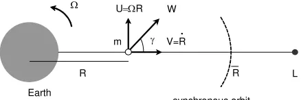
DYNAMICS OF A SINGLE MASS A point mass is considered moving along a tether of length L, assuming that the tether is rigid and co-rotates with the Earth (radius RE) at constant angular velocity Ω, as shown in Fig. 1. As the mass moves along the tether, it experiences a transverse coriolis force resulting in friction between the particle and tether, which is considered in Ref. 5.
m γ Ω
Earth
synchronous orbit V=R
U=ΩR
R
.
R L
[image:2.595.63.282.244.317.2]W
Fig. 1: Schematic space elevator of length L co-rotating with angular velocity Ω.
For the frictionless case, the effective potential φ is the sum of the gravitational potential of the Earth and a potential which represents the centripetal acceleration defined as
( )
R
R
R
µ
φ
=
−
2Ω
2−
2
1
(1)
where µ is the gravitational parameter of the Earth and R is the distance of the particle from the centre of the Earth. This 1-dimensional problem is conservative and can be described by a 2-dimensional phase space with Hamiltonian
H
(
R
,
R
&
)
defined by( )
R
R
R
R
=
2+
φ
2
1
)
,
(
&
&
H
(2)Because the system is conservative and the problem immediately presents an integral of motion given by
so that
0
)
,
(
R
R
&
=
&
H
C
R
R
,
)
=
(
&
H
R
R
R
−
Ω
−
µ
=
2 2 22
1
2
1
&
C
(3)This integral allows the phase space of the problem to be explored for level curves of C. Then, the equation of motion of the particle can be determined from the Hamiltonian using
R
&
=
∂
H
∂
R
&
andR
&
&
=
−
∂
H
∂
R
which yields2 2
R
R
R
&
&
=
Ω
−
µ
(4)It is clear from Eq. (4) that a single equilibrium point exists when the radial acceleration vanishes at the point
R
=
R
, defined by 3 1 2 0 ) , ( ⎥⎦ ⎤ ⎢⎣ ⎡ Ω = ⇒ = ∂ ∂µ
R R R R & H (5)which corresponds to a single equilibrium point E at synchronous radius (6.6 Earth radii). The nature of this equilibrium point can now be determined from the Hamiltonian. To demonstrate this, the class of turning point of the Hamiltonian can be found from6
( )
3 2 2 2 2 2 2 2 2 R R R R R R q µ − Ω − = ⎥ ⎦ ⎤ ⎢ ⎣ ⎡ ∂ ∂ ∂ − ∂ ∂ ∂ ∂ = & & H H H (6)so that, substituting Eq. (5),
q
( )
R
=
−
3
Ω
2demonstrating that the equilibrium point is hyperbolic (
H
has a saddle point atR
=
R
) and unstable. The eigenvalues λ of the linear system in the neighbourhood of the hyperbolic point E can also be determined from the characteristic polynomial P defined by6( )
2 2 2 02 2 2 2 2 = − ⎥ ⎥ ⎥ ⎥ ⎦ ⎤ ⎢ ⎢ ⎢ ⎢ ⎣ ⎡ ∂ ∂ ∂ − ∂ ∂ − ∂ ∂ ∂ ∂ ∂
= I x
R R R R R R
P λ λ
& & & H H H H (7)
which, from Eq. (2), reduces to
Ω ± = ∂ ∂ − ± = = 3 2 2 R R R H
This pair of real eigenvalues correspond to stable (
−
3
Ω
) and unstable (+
3
Ω
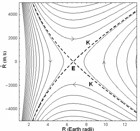
) manifolds attached to E, shown in Fig 2. Because E is a saddle point, it represents a potential barrier to particles attempting to transit it from either direction along the tether, represented by the transit and no-transit phase paths shown in Fig. 2. Level curves parameterised by C are shown in Fig. 3, where the equilibrium E corresponds to a hyperbolic fixed point. The stable and unstable manifolds are a linearization of the separatrix K which discriminates globally between transit and no-transit paths.R
E + -
+ - NT NT
R .
[image:3.595.85.223.251.374.2]T T
Fig. 2: Schematic hyperbolic fixed point E with stable (-) and unstable manifolds (+), transit (T) and no-transit (NT) phase paths.
Fig. 3: Phase paths for particles freely moving along a space elevator with separatrix K.
Because the Hamiltonian of the problem forms an integral, the radial speed V of a particle moving freely along the tether can be obtained from Eq. (3) as
( )
C
R
R
R
V
2=
2Ω
2+
2
µ
+
2
(9)while the transverse speed U is given by
( )
2=
2Ω
2R
R
U
(10)Therefore, the angle γ of the absolute velocity of the particle relative to the tether can be written as
( )
12 2 tan
2 2
→ + + Ω
Ω =
C R R
R R
µ
γ (11)
which yields the limit γ →π 4 for large R. Similarly, the absolute speed of the particle W
can be obtained from Eq. (9) and Eq. (10) as
( )
= Ω + + C → RΩR R
R
W 2 2 2 2µ 2 2 (12)
which yields a limiting speed of 2RΩ for large R.
For particles moving down the tether, after being captured at the end, the effective particle energy C must be such that the particle can cross the potential barrier at E and avoid being reflected back on a no-transit phase trajectory. Evaluating C at E, the following function can be defined
( )
(
)
⎟⎟
⎠
⎞
⎜⎜
⎝
⎛
−
+
−
Ω
=
R
R
f
2 2 22
1
1
ξ
µ
ξ
ξ
(13)for arbitrary ξ, such that to ensure transit of E it is required that −V
( )
L f f( )
L . Similarly, for particles ascending the tether under power, if V( )
R f f( )
R then the particle will pass through E and escape with no further external work required. Clearly, there are issues concerning the optimum strategy to ascend and descend the tower (minimum-time, minimum-energy), however these are beyond the scope of this paper.DYNAMICS OF A CHAIN OF MASSES The analysis for a single mass can now be extended to a chain of N masses, as shown in Fig. 4. Each element of the chain comprises a mass m connected to neighbouring masses by a (massless) tether
[image:3.595.58.283.441.651.2]of length d. An individual mass in the chain will experience gravitational and centripetal forces, in addition to internal tension forces from its nearest neighbours in the chain. For an appropriate number of mass elements and mass spacing the entire system can be configured to remain in equilibrium. The resultant gravitational and centripetal forces acting on the system then balance. This is a discrete form of the continuous hanging tower defined by Pearson.1
Ω
Earth M
synchronous orbit R L d
[image:4.595.63.279.626.725.2]m
Fig. 4: Chain of N masses of length L co-rotating with angular velocity Ω.
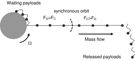
Consider now the effect of increasing the length of the tower beyond that required for equilibrium. Then, there will be an excess of centripetal force acting on the chain of masses above synchronous orbit which can be used to lift new payloads from the surface of the Earth, as shown in Fig 5. The masses which are beyond synchronous orbit are forcing the lower masses in the chain across the effective potential barrier, discussed earlier for the single mass case. An ‘orbital siphon effect’ can then be established where as a new payload is added to the bottom of the chain, a payload is released from the top so that the overall length of the chain does not change. However, there is a net radial force which will maintain the flow of mass from the surface of the Earth to Earth escape.
Waiting payloads
FG>FC
Ω
Released payloads Mass flow synchronous orbit
FC>FG
Fig. 5: Schematic space elevator ‘orbital siphon’ effect.
The total force acting on each mass in the chain can be determined from the sum of the gravitational and centripetal forces along with the tension forces exerted by the nearest neighbours on the chain. For the jth mass, the total force is given by
(
R jd)
m(
R jdGMm
f E
E
j + Ω +
+ −
= 2
2
)
(14)The internal tension forces are not explicitly listed here since they will vanish during a summation over the chain of masses to be performed later. In non-dimensional form the force on the jth mass can then be written as
(
j)
(
jfj λ
λ +Λ + +
−
= 1
1 1
2
)
(15a)GM R R
d f
GMm R
f E
E j
E j
3 2 2
,
, = Λ= Ω
= λ (15b)
where Λ is the ratio of the centripetal and gravitational forces exerted on a mass at RE. In order to determine the conditions for equilibrium in the chain of masses, the net resultant force can be found from the summation
∑
= =
N
j
j f F
0
(16)
Then, performing the summation using Eq. (15), it can be shown that the net resultant force on the chain of masses is given by
(
)(
)
( )
(
)
( )( )
[
ψ λ ψ λ]
λ
λ
1 1
1 1
2 1 2 1
1 1
2 + + −
+
+ + Λ =
N N N
F
(17)
where ψ( )m
( )
z is the polygamma function, defined in series form as
( )
( ) ( )
∑
∞(
)
( )=
+ −
+ +
− =
0
1 1
! 1
k
m m
m
k z m z
ψ (18)
0
0 =
=
∑
=
N
j
j f
F (19)
5
This requirement then defines the length of the chain for a given number of masses N, as listed in Table 1. It can be seen that for a large number of masses the length of the chain approaches that defined by Pearson1 for a continuous hanging tower. The net non-dimensional force acting on a chain with
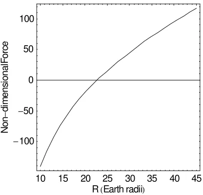
N=1000 is shown in Fig. 6. It can be seen that the chain will be in equilibrium for a given length (22.7 Earth radii). If the chain is longer than this equilibrium length the chain will rise, while if the chain is shorter the chain will fall, resulting in an unstable equilibrium7 as expected from the analysis of a single mass.
N 5 50 500 5000 ∞
[image:5.595.64.272.377.576.2]L (RE) 95.51 25.91 22.92 22.68 22.65
Table 1: Mass chain length L required for equilibrium as a function of number of masses N.
10 15 20 25 30 35 40 45
RHEarth radiiL
-100
-50 0 50 100
n
o
N
-l
a
n
oi
s
n
e
mi
de
cr
o
F
Fig. 6: Resultant non-dimensional force acting on a chain of masses as a function of length (N=2000).
The orbital siphon effect described here utilises the excess centripetal force acting on the chain of masses above synchronous orbit to lift new payloads from the surface of the Earth. The parameter Λ is therefore an important measure of the performance of such as system. It can be seen from Table 2. that the Earth is clearly the most attractive terrestrial planet for such a system, although the same principles could be used effectively on asteroids to deliver mass to escape in a continuous stream.
Body Mercury Venus Earth Vesta
Λ 3.5 x10⁻⁵ 5.8 x10⁻⁴ 3.5 x10⁻³ 0.78
Table 2: Parameter Λ (ratio of centripetal to gravitational force) for a range of bodies.
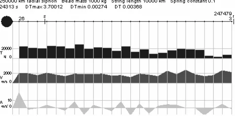
ORBITAL SIPHION OPERATION The primary siphon numerical model8 used a simple 2D model of orbiting masses, tied together by elastic cables, and connected to the Earth's equator, to simulate the tower dynamics. The model was initialised as a stationary tower with some 25 masses connected by equal length elastic ties along a 250,000 km radius tower. The simulation then released the tower at its base, and added new masses at the base as the lowermost tie tension exceeded the gravitational force at the Earth's surface. Masses travelled up the tower and were released once their radial distance exceeded 250,000 km. Most of the comments in this section derive from this numerical model, and from a subsequent second 1D numerical simulation model.9
No lateral forces act on stationary towers, so such towers have no need for lateral constraint. However, coriolis forces act on rising towers to push them westward on an eastward-rotating planet. If not counteracted, these forces act to reduce the angular velocity of the masses in the rising tower, and consequently the net force exerted by the tower. Consequently a laterally unconstrained tower will only lift a limited amount of mass before losing tension and shape, as shown in Fig 7.
Fig. 7: Tower losing tension and becoming non-radial.
a. The rising tower is constrained to a radial path by a cantilever truss running along its entire length, all of whose components would be in tension The rising tower might be compared to a 'train' running along a 'track' provided by the cantilever truss (Fig. 8).
b. The rising tower is itself stiffened by being constructed in the form of a rigid or semi-rigid cantilever truss.
[image:6.595.49.287.627.745.2]c. The rising tower uses lateral thrusters to maintain a radial path.
Fig. 8: Cantilever truss siphon.
With the rising tower constrained to a radial ascent, the force exerted by the tower implies a constant acceleration. If the radial velocity is to be constrained to some limit VR, some braking mechanism is needed. The most obvious location for a braking mechanism would be at the base of the tower, where new masses are added into the rising tower (braking can be used to generate power).
Furthermore, with fixed length ties, each new mass added at the base of the tower is raised and accelerated from rest to
VR in a short interval of time. This results in a brief increase in tension in the lowermost tie, which subsequently propagates up the tower (Fig. 9). Equally, when a mass is released from the top of the tower, tension vanishes from the topmost tie, and this subsequently propagates down the tower. In addition, the entire tower will have a natural frequency of radial oscillation.
Fig. 9: Orbital siphon simulation for 250,000 km tower showing tension, radial velocity and acceleration.
Also Pearson's stationary tower was tapered to create a constant stress along the length of the tower, with the tower having the greatest cross-sectional area at the tension maximum at synchronous orbit. A rising train of masses, however, cannot have its cross-sectional area widened and narrowed as it rises, and so the train will have the highest tension per unit cross-section at synchronous orbit. This stress maximum, combined with tension waves propagating up an down the tower, would appear to result in very high loads within the tower.
The simulation models assumed ideal rather than actual material components. No account was included of the operation of other forces (e.g. lunar and solar gravitation). No attempt was made to model a cantilever truss, or any sort of braking mechanism.
The broad conclusions drawn from these simple simulation models were, firstly, that in principle the siphon could indeed operate to raise up and release a continuous chain of mass, and that secondly the siphon could also draw up a chain of increasing
mass (and thus to pull a larger version of itself up by its own bootstraps), and that the siphon could also be used to 'fire' a string of masses in a selected direction – leveraging energy from the Earth’s rotation. However, the requirements of maintaining a radial ascent path, of braking of the accelerating tower, and of minimizing the tension peaks propagating along the rising tower, present a set of formidable obstacles to the construction of such an edifice.
CONCLUSIONS
7
REFERENCES 1
Pearson, J., “The Orbital Tower: A Spacecraft Launcher Using the Earth’s Rotational Energy,” Acta Astronautica, Vol. 2, No. 9-10, 1975, pp. 785-799.
2
Clarke, A.C., “The Space Elevator: Thought Experiment or Key to the Universe,”
Advanced Earth Oriented Applications of Space Technology, Vol. 1, 1981, pp. 39-48. 3
Edwards, B.B., “Design and Deployment of a Space Elevator,” Acta Astronautica, Vol. 47, No. 10, 2000, pp. 735-744.
4
Smitherman, D.V., Space Elevators: An Advanced Earth-Space Infrastructure for the New Millennium, NASA Report CP-2000-210429, Marshall Space Flight Center, Huntsville, 2000.
5
McInnes, C.R., “Dynamics of a Particle Moving Along an Orbital Tower,” Journal of Guidance, Control and Dynamics, Vol. 28, No. 2, 2005, pp. 380-382.
6
Jordan, D.W. and Smith, P., Nonlinear
Ordinary Differential Equations, 3rd edition, Oxford University Press, Oxford, 1999, pp. 78-80.
7
Steindl, A. and Troger, H., Is the Sky-hook Configuration Stable, Nonlinear Dynamics, Vol. 40, No. 4, 2005, pp. 419-431.
8
http://www.idlex.freeserve.co.uk/siphon/siph on.html
9
http://www.idlex.freeserve.co.uk/siphon/anal ytics/anasiphon.html
A Personal Postscript (C. Davis): Origins of the Siphon
The idea for the siphon first occurred to me in 1991, while I was conducting an unrelated thought experiment. I had imagined that an attempt was being made to mine a small asteroid for its carbon, by sending a single self-reproducing mechanical digger truck to the asteroid, with instructions to dig up carbon and transport it to a collection site on the asteroid equator. As the mechanical diggers multiplied exponentially in numbers, more and more carbon was delivered to the collection point, creating a steadily growing conical heap of carbon.
While this seemed a neat way of extracting carbon, I hadn't thought how to collect and transport the carbon back to Earth. While I was trying to think of some cheap transportation method, the carbon heap grew higher and higher, with the digger trucks struggling up to the top to deposit their loads. It was while I was considering this scene that I found myself imagining carbon
flying off the top of the the conical heap, dragging trucks with it, one after another.
This was a distinctly odd notion, but I soon realised that it wasn't entirely implausible. If the carbon heap had grown so high that it rose above the synchronous orbit of the rapidly rotating asteroid, material would indeed fly off the top, because centrifugal or inertial forces would exceed gravitational forces. However what wasn't clear was whether such a mountain would allow a continuous stream of material to flow into space in a siphon effect.
The matter then rested there for several years, while the mechanical diggers went on to form the foundation of the Idle Theory of evolution. Then, in 1996, with the advice and assistance of a physicist friend, Dr Andrew Gay, I put together a 2D simulation model of orbiting satellites - something I had wanted to do for a long time. Once I had this model, it almost immediately occurred to me that I could maybe use it to explore the siphon idea. I began connecting satellites into chains with elastic cables, and connected one end of the chain to the equator of the Earth, to create an orbital tower along the lines of Pearson's 1975 tower - only higher.
The first attempt to simulate the siphon simply entailed releasing this tower at its base, and feeding in new satellites as it rose. But, after lifting a few satellites up from the Earth, the tower simply slowed, became misshapen, and finally collapsed. At first I thought that I had simply shown that the siphon idea was unworkable. But then I remembered that the conical pile of carbon on the asteroid was an inflexible and rigid mountain. So I took my simulation model, and made the tower rigid by simply removing all tangential forces acting on it, so as to constrain it to radial motion. With this fix in place, the siphon effect began to work. In fact, it began to work rather too well, with satellites accelerating up the tower faster and faster.