City, University of London Institutional Repository
Citation:
Yan, S. ORCID: 0000-0001-8968-6616, Li, Q. ORCID: 0000-0001-7456-7868,
Wang, J. ORCID: 0000-0003-1821-2362, Ma, Q. ORCID: 0000-0001-5579-6454, Xie, Z. and
Stoesser, T. (2019). Comparative Numerical Study on Focusing Wave Interaction with
FPSO-like Structure. International Journal of Offshore and Polar Engineering, 29(2), pp.
119-157. doi: 10.17736/ijope.2019.jc754
This is the accepted version of the paper.
This version of the publication may differ from the final published
version.
Permanent repository link:
http://openaccess.city.ac.uk/22493/
Link to published version:
10.17736/ijope.2019.jc754
Copyright and reuse: City Research Online aims to make research
outputs of City, University of London available to a wider audience.
Copyright and Moral Rights remain with the author(s) and/or copyright
holders. URLs from City Research Online may be freely distributed and
linked to.
City Research Online:
http://openaccess.city.ac.uk/
[email protected]
Comparative Numerical Study on Focusing Wave Interaction with FPSO-like Structure
Shiqiang Yan
1,
Zhihua Xie
2*, Qian Li
1, Jinghua Wang
1, Qingwei Ma
1, Thorsten Stoesser
31: School of mathematics, Computer science and engineering, City, University of London, London, UK
2: School of Engineering, Cardiff University, Cardiff, UK
3: Department of Civil, Environmental and Geomatic Engineering, University College London, London, UK
*Corresponding author: [email protected]
ABSTRACT
Evaluating the interactions between offshore structures and extreme waves plays an essential role for securing the survivability of the structures. For this purpose, various numerical tools, e.g. the fully nonlinear potential theory (FNPT), the Navier-Stokes (NS) models and hybrid approaches combining different numerical models, have been developed and ultilised. However, there is still a great uncertainty over the required level of model fidelity when being applied to a wide range of wave-structure interaction problems. This paper aims to shed some light on this issue with a specific focus on the overall error sourced from wave generation/absorbing techniques and resolving the viscous and turbulent effects, by comparing the performances of three different models, including the quasi Arbitrary Lagrangian Eulerian Finite Element Method (QALE-FEM) based on the FNPT, an in-house two-phase NS model with large-eddy simulation(LES) and a hybrid model coupling the QALE-FEM with the OpenFOAM/InterDymFoam, in the cases with a fixed FPSO-like structure in extreme focusing waves. The relative errors of numerical models are defined against the experimental data, which are released after the numerical works have been completed (i.e. a blind test), in terms of the pressure and wave elevation. It provides a practical reference for not only choosing an appropriate model in practices but also on developing/optimizing numerical tools for more reliable and robust predications.
KEY WORDS:
Wave-structure interaction, comparative study, blind test, FNPT, NS models, LES.INTRODUCTION
Understanding the characteristics of the interaction between the extreme waves and structures, as well as a reliable prediction of the behavior of the structures in a realistic extreme sea, plays a fundamental role in the safe and cost-effective design of coastal and offshore structures, and marine renewable devices. Such assessments
and predictions can always be performed in a laboratory environment or in a numerical wave tank, where the extreme waves are often modeled by using a focusing wave based on the spatial-temporal focusing mechanism (Ma, et al., 2015) or the NewWave theory (Tromans, et al., 1991).
In design practices, classical approaches in frequency domain are employed, such as linear and second order theories, which however are shown to be insufficient when higher-order nonlinear effects are pronounced. Such higher-order nonlinearities have been pointed out to play important roles in the interactions between extreme waves and
structures (Zang, et al., 2010). To overcome this drawback, approaches in time domain with considering sufficient nonlinearities
have been developed. These include the fully nonlinear potential theory (FNPT) and the general viscous flow theory (NS), which is formulated by the Navier-Stokes equations. The FNPT model, which
assumes that the flow is inviscid and irrotational, is solved by different numerical methods, such as the boundary element method (e.g. Longuet-Higgins & Cokelet, 1976; Grilli, et al. 2001), finite element method (e.g. Wu & Eatock-Taylor, 2003; Yan & Ma, 2007; Ma & Yan, 2009), spectral element method (e.g. Engsig-Karup, et al. 2016). The NS model does not have the assumptions of the FNPT model. However, in the real application of the NS model to the wave-structure interactions, certain degrees of simplification might be applied, resulting different forms of the NS models with main diversities including (1) one-phase (Ma 2005; Zhou and Ma, 2010; Lind et al,
2012; Zheng et al, 2014) or two-phase (Chen et al, 2014; Hildebrandt and Sriram, 2014; Ferrer et al, 2016; Hu et al., 2016; Xie, 2012); (2) compressible (Yang et al., 2016) or incompressible (Yang et al.,
2017). The significant diversities also exist in terms of numerical approaches on (1) how to solve the governing equation, for which both the conventional mesh-based methods, e.g. the finite volume method (Chen, et al., 2014; Hildebrandt & Sriram, 2014; Xie, 2015; Yang et al., 2017) or meshless methods, e.g. the smoothed particle hydrodynamics (SPH, e.g. Lind, et al., 2012; Zheng, et al., 2014) and the meshless local Petrov-Galerkin (MLPG_R) method (Ma, 2005; Zhou & Ma, 2010; Sriram & Ma, 2012), have been attempted; (2) how to track or capture the free surface, e.g. the volume of fluid (VOF, e.g. Hu et al., 2016; Xie, 2012) and level set method (Zhang et al, 2009; Yang et al, 2017); and (3) how to model the turbulence, e.g. the Reynolds Averaged NS (Yang et al, 2016) or Large-eddy simulation
Generally speaking, the computational demands of FNPT models are
considerably lower than those of NS models. The accuracy and reliability of the FNPT models on simulating extreme wave evolutions have been widely recognized (e.g. Yan and Ma, 2010b; Engsig-Karup,
et al. 2016; Wang et al., 2018). However, the FNPT models cannot
reliably capture the small-scale viscous and turbulent effects, which may be significant near the structures, e.g. the slamming and breaking wave impact on structures (Dias and Ghidaglia, 2018), wave motions in a small region confined by structures (e.g. Lu and Chen, 2012), due to their theoretical assumption. This initiates the developments of hybrid approaches combining the FNPT or other simplified models with a NS model for robustly modelling the wave-structure interactions. The fundamental idea of the hybrid approach is that in the regions where the viscous/turbulent effects are significant, e.g., near the breaking waves and the structures, the NS model is utilised to resolve small- and micro-scale physics, e.g. the vortex shedding and flow separation; in other regions, e.g. the wave propagation away from the structures, the FNPT model or other simplified models are
employed. Models based on the velocity-decomposition (e.g. Ferrant
et al., 2003; Luquet et al., 2007, Ferrant et al., 2008; Edmund et al.,
2013) and the domain-decomposition (e.g. Yan and Ma 2010; Hildebrandt et al., 2013; Sriram et al., 2014; Fourtakas et al., 2017; Yan and Ma, 2017; Higuera et al., 2018; Li & Wang et al., 2018) have been developed. Systematic reviews on the development of the hybrid models can be found in Sriram et al., (2014) and Li & Wang et al.
(2018).
Comparative studies have been carried out to investigate the performances of different models for specific problems aiming to provide a reference or guideline for the selection of suitable numerical models, e.g. on the water entry problem (Hong et al., 2017) and slamming impact (Dias and Ghidaglia, 2018). It has found that different numerical tools (theories) or the same numerical tool run by different persons may produce considerably different results (e.g. Hong et al., 2017). This implies that there is still a great uncertainty over the required level of model fidelity when being applied to a wide range of wave-structure interactions. Such uncertainty may be sourced from effectiveness of generating incoming waves, physical simplification, numerical truncation error and discretization. This paper focuses on a quantitative assessment of the overall performance of different models. The problem to be considered is a focused wave interaction with a fixed FPSO-like structures. The wave conditions, FPSO model, arrangements of the pressure sensors and wave gauges are pre-specified by the CCP-WSI consortium (www.ccp-wsi.ac.uk) through its blind test workshops. Three numerical methods including the QALE-FEM based on the FNPT (Ma and Yan, 2009), a two-phase NS model with LES (Xie, 2015) and a hybrid model coupling the QALE-FEM with OpenFOAM/InterDymFoam (Li & Wang et al., 2018). In order to realistically reflect the overall performance of different numerical models in practices without artificial numerical calibration or data smoothing, the comparison was carried out using a blind-test approach, in which the experimental data were released after the numerical simulations have been completed. However, it causes diversities in numerical practices, e.g. the wave generation and absorption, the computational domain sizes, the fluid properties and computing hardware.
NUMERICAL METHODS
The QALE-FEM method is based on the FNPT. The velocity potential and its time derivative, which is required by the Bernoulli’s equation for the pressure evaluation, are governed by the corresponding Laplace’s equations and solved by boundary value problems, where
the free surface boundary condition is written in an arbitrary Lagrangian-Eulerian form (Li & Wang et al, 2018), using the FEM. The details of the FEM formulations and the time integration scheme have been discussed in our previous publications, e.g. Ma et al.
(2001). The main differences between the QALE-FEM method and the conventional FEM method is that the computational mesh in the QALE-FEM is moving by using a novel methodology based on the spring analogy method but purpose-developed for wave-structure interaction problems. The details of the QALE-FEM are referred to Ma and Yan (2009) and Yan and Ma (2007).
The two-phase NS model developed by Xie (2012, 2013, 2014, 2015 and 2017) employs the LES approach with the dynamic Smagorinsky sub-grid scale (SGS) model (Lily, 1992). The high-resolution VOF scheme CICSAM (Compressive Interface Capturing Scheme for Arbitrary Meshes) (Ubbink, 1997) is used for identifying the water/air phase and thus the free surface. The governing equations are discretised using the finite volume method (FVM) on a staggered Cartesian grid. The advection terms are discretised by a high-resolution scheme (Xie, 2012), which combines the high order accuracy with monotonicity, whereas the gradients in pressure and diffusion terms are obtained by central difference schemes. In order to deal with complex geometries in Cartesian grids, the partial cell treatment in 3D (Xie, 2015) was utilized in the finite volume discretisation. The SIMPLE algorithm (Patankar, 1980) is employed in for the pressure-velocity coupling and a backward finite difference discretisation is used for the time derivative. More details of this model can be found in Xie (2012, 2013, 2014, 2015 and 2017). The computer code is parallelized using MPI and a domain decomposition technique.
The hybrid FNPT-NS solver, qaleFOAM, combines the QALE-FEM and OpenFOAM using a zonal approach, in which the FNPT domain, governed by the QALE-FEM, covers the whole computational domain and the NS domain is a confined zone around the structure, governed by the multiphase NS solver OpenFOAM/
interDyMFoam
. On the coupling boundary, the velocity, pressure and wave elevation for the NS solver are provided by the QALE-FEM. A relaxation zone is applied near coupling boundaries to (1) absorb the reflected waves from the structures, and (2) ensure a smooth transition of the solution.It shall be noted that the solution in the NS domain does not feedback to the FNPT domain and the coupling of two models in this paper is a weak (one-way) coupling. More details of the qaleFOAM can be found in Li & Wang et al. (2018).
EXPERIMENTS AND CASE CONFIGURATIONS
The experiments were performed in the wave basin at the University of Plymouth, which features 35 m in length, 15.5 m in width and 2.93 m in depth. Flap wave paddles are installed to generate three-dimensional waves. A simplified FPSO with two ends being semi-circles (0.15 m radius) is used in the experiments. The length, width and the height of the FPSO model is 1.2 m, 0.3 m and 0.3 m, respectively, as illustrated in Fig. 1. The temporal variations of surface
elevation at various locations are recorded by wave gauges with a
sampling frequency of 128 Hz. Those near or on the surface of the FPSO are illustrated in Fig. 1. Six pressure sensors are installed near the bow of the FPSO surface. Pressure sensors P1, P2 and P3 are
placed at the bow and located at 0.05 m above mean free surface (MWL), in line with the MWL and 0.05 m below the MWL,
respectively. The vertical spacing of the sensor groups P4-P6 are the same as P1-P3, but they are located at 45o about the longitudinal axis
waves are generated by using flap wave paddles whose motions are
specified by using the 2nd order wavemaker theory. JONSWAP
spectrum with different significant wave heights (Hs) and peak periods
(Tp) are considered in this study. The parameters describing the wave
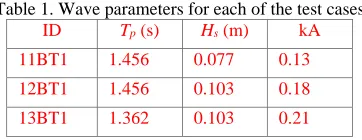
[image:4.612.39.283.116.274.2]conditions, including the local wave steepness (kA), are summarized in Table 1.
[image:4.612.74.255.308.378.2]Fig. 1: Sketch of the experimental configuration (duplicated from https://www.ccp-wsi.ac.uk/blind_test_series_1)
Table 1. Wave parameters for each of the test cases
ID Tp(s) Hs (m) kA 11BT1 1.456 0.077 0.13
12BT1 1.456 0.103 0.18
13BT1 1.362 0.103 0.21
NUMERICAL RESULTS AND DISCUSSION
Numerical configurations
The numerical wave tank used by the QALE-FEM has the same size as the experimental wave basin, i.e. 35m × 15.5m× 2.93m. To accelerate the simulation, the approach using the concept of the overset grid method (Ma et al. 2015) is applied. In this approach, two sets of computational mesh are used. One covers the entire computational domain without the FPSO for modelling the nonlinear incident waves. Since the incident wave is unidirectional, the mesh size in the direction normal to the wave propagation can be very coarse, e.g. 4 cells along the transverse direction of the tank. Another one covers a confined zone near the FPSO, i.e. a circular domain with diameter of 7 m centred at the geometric centre of the FPSO. At the outer boundary of the confined zone, the free surface elevation and the
fluid velocity are specified by using the solutions from the first set of mesh. A translational zone with a width of 1 m is placed near the outer boundary of the confined zone, in order to damp the reflection from the FPSO.
The computational domain and the mesh resolution used in the FNPT domain of the qaleFOAM is the same as the first set of mesh in the QALE-FEM. The NS domain of the qaleFOAM has a size of 5.4 m×3 m×3.53 m, where the width of the relaxation zone attached to the outer boundary of the NS domain is 0.6 m. The FPSO is placed at the centre of the NS domain. A laminar model is used in the NS domain.
Free-slip boundary conditions are imposed at the bottom, top and side walls of the wave tanks in order to avoid resolving the boundary layers.
The computational domain of the two-phase NS model with LES has a size of 6m × 3m × 3.3m. The structure is 2.37 m away from the inlet, which is exactly the distance between the wave gauge WG1 and the
bow of the structure in the experiment. With this setup, the measurement at WG1 can be used directly to specify the inlet wave condition. On the structure boundary, the wall model is used for the near-wall treatment in the LES modelling. On other boundaries, the same boundary conditions as the NS domain of the qaleFOAM are ultilised.
Wave Generation and Absorption
In the QALE-FEM and the qaleFOAM, the wave is generated by using a wavemaker. Due to the fact that the wave paddle motions are unknown, it is necessary to find the wavemaker motion to reproduce the incident waves. To do so, the self-correction technique (Ma, et al., 2015) is employed in this study. For all cases considered here, the wave elevation recorded by WG1 in the empty-tank test without the FPSO is used as the targeted wave to reproduce the wavemaker motion. After that, the same wavemaker motions are used to drive the wavemakers in the QALE-FEM and the qaleFOAM simulations. In the LES model, the wave is generated by specifying the inlet boundary condition in terms of the wave elevation, velocity and pressure, for which the wave elevation recorded at WG1, placed at the inlet of the LES domain, in the empty tank test is used to derive the wave spectrum and the linear wave theory is adopts to find the particle velocity and elevation at the inlet of the computational domain.
Fig. 2 Comparison of wave elevations recorded at WG1 in the empty-tank test of Case 12BT1
In order to check effectiveness of the wave generation, the time
histories of the wave elevation at WG1 are compared with the experimental data (Fig. 2). Since the QALE-FEM and the qaleFOAM
use the same wave generation technology, the results at WG1 are identical and agree well with the experimental data; whereas a noticeable discrepancy is observed between the LES results and the experimental data.
It is worth noting that the wave generation by specifying the inlet boundary conditions using the wave theory for steady wave, e.g. the linear and 2nd order wave theories, can result in a satisfactory result
but is subjected to a technical constraint, i.e. the wave spectrum at the inlet must be known at prior. This means that the inlet boundary (wave generation boundary) must be placed at a location where the time history of the wave elevation is known and recorded by a wave gauge. If such a gauge position (as well as the inlet boundary of the computational domain) is too far away from the structures, the computational domain may become unnecessarily big, leading to a long CPU time; if it is too close to the structures, there might be an
[image:4.612.341.554.342.416.2]in the QALE-FEM and the qaleFOAM can well capture the nonlinear wave evolutions, as demonstrated by Fig. 3, which compares the wave elevations at other positions, i.e. WG16 and WG24, using the
QALE-FEM with the experimental data. This means that the boundary of the NS domain in the qaleFOAM can be placed at any positions, even though there are no measured data available. The QALE-FEM in the qaleFOAM can provide an accurate prediction of the wave kinematics at the inlet of the NS domain. This can be further evidenced by the satisfactory agreement between the qaleFOAM results with the experimental data in Fig. 3, in which the inlet of the NS domain is placed 2.1 m upstream to the bow of the FPSO. In other words, the
[image:5.612.333.558.39.180.2]coupling of the QALE-FEM and the NS solver in the qaleFOAM provides a robust way to explore both the large-scale nonlinear wave evolution and the small-scale physics such as the viscous and turbulent effects near the structures simultaneously (Li & Wang et al, 2018).
Fig. 3 Comparison of wave elevations recorded at WG16 and WG24 in the empty-tank test of Case 12BT1
[image:5.612.52.274.203.359.2]In the QALE-FEM and qaleFOAM, a self-adaptive wavemaker is adopted in the right end of the numerical wave tank to absorb the wave, avoiding reflection from the outlet. In the LES model, the zero-gradient or radiation boundary conditions are applied for the flow at the outlet of the computational domain.
Table 2: Computational mesh in the NS domain of QALE-FEM
Mesh No Mesh grid number Number of grids on the structure surface
M1 2352996 958
M2 3449136 3576
M3 3797136 7576
Extreme Wave Interaction with FPSO-like Structure
The main focus of this paper is to compare the performance of three models in the cases with FPSO. The results are discussed in this section.
[image:5.612.334.552.215.447.2]Convergence
Fig. 4 Wave elevations recorded at different wave gauges in the cases with different mesh sizes using the QALE-FEM(Case 13BT1)
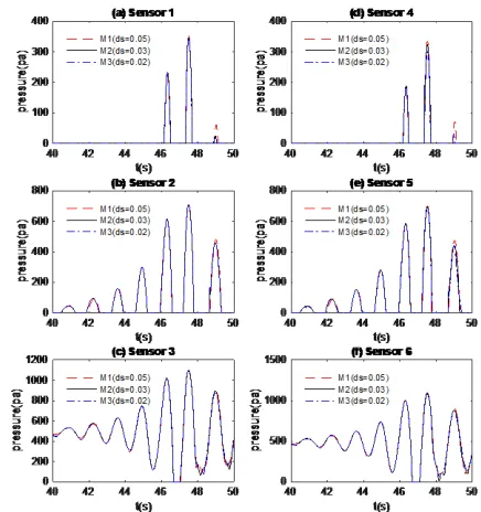
Fig. 5 Time histories of the pressure recorded at different locations in the cases with different mesh sizes using the QALE-FEM (Case 13BT1)
Convergence investigations are carried out using meshes with different resolutions. In the QALE-FEM simulation, the time step size adopted is the same as the experimental sampling time interval, i.e. 128 Hz. Three sets of the computational mesh, where the characterized mesh size on the free surface ranges from 0.02 to 0.05 m and the characterized mesh size near the structure surface ranges from 0.01 to 0.025 m. The mesh size exponentially increases from the free surface to the tank bottom. Table 2 summarises three sets of mesh used by the QALE-FEM. Some results obtained by the QALE-FEM are shown in Fig. 4 and Fig. 5 to shed lights on the convergence property of the QALE-FEM. These figures, respectively, illustrate the time histories of the wave elevation and pressure recorded at different locations for Case 13BT1, which involves the steepest wave in this paper. As observed, the corresponding results using M2 is similar to those adopting M3 (finest resolution) but different from those applying M1 (coarsest resolution). A similar phenominon is also observed in other cases. This justifies that M2 is sufficient for the QALE-FEM to obtain the convergent solution.
[image:5.612.36.293.466.540.2]the qaleFOAM is dynamically updated by satisfying the Courant condition in the NS domain, i.e. the Courant number is smaller than 0.5, due to the fact that the time step required to obtained convergent results by the QALE-FEM is larger than that by the NS solver. In the FNPT domain of the qaleFOAM, the characterized mesh size on the free surface is approximately 0.03 m in the longitude direction for all cases presented here. Three set of computational mesh used in the NS domain of the qaleFOAM. Detailed results for the convergence of the qaleFOAM has been discussed in Li & Yan et al (2018) and the corresponding results will not be repeated here. The time step used in the LES modelling is uniform, i.e. 0.0001 s. The computational domain of the LES is discretized using a uniform grid of 320 × 320 × 160 points in the longitude (streamwise), vertical and transverse (spanwise) directions, respectively. The total number of cells is approximately 16.4 M. The choice of such mesh resolution is based on the experience in modelling the wave-structure interaction (Xie, 2015) and a further confirmation that the predictions using this mesh agree well with a corresponding result with a slightly coarser mesh.
Fig. 6 Time histories of the wave elevation recorded at different positions (Case 12BT1)
Overall Accuracy
[image:6.612.333.555.47.279.2]In this section, the convergent results from the QALE-FEM, the LES and the qaleFOAM are compared with the experimental data in order to compare the overall performance of these models on numerically simulating the fixed FPSO in non-breaking extreme waves.
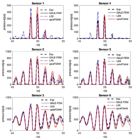
Fig. 7 Time histories of the pressure recorded at different positions on the FPSO surface(Case 12BT1)
The first case considered is Case 12BT1, where the focusing wave steepness kA = 0.18. Fig. 6 compares the wave elevations recorded at different positions near the FPSO. At the positions away from the FPSO, i.e. WG7 (Fig.6(e)) and WG18(Fig. 6(d)), the waves are less disturbed by the FPSO, and, therefore, the corresponding results can be used to evaluate whether the incoming waves are well reproduced by different wave generation approaches. From Fig. 6(d) and (e), it is observed that the numerical results by the QALE-FEM and the qaleFOAM, where the self-correction wavemaker technology is used, agree well with the experimental data; whereas the results obtained by the LES, in which a linear wave theory is used to specify the inlet boundary condition, show noticeable discrepancies with the experimental data, especially in terms of the occurrences of the highest wave crest in Fig. 6(d), as well as at the inlet (Fig. 2). For the LES, similar phenomenon is also found on the runup (Fig. 6 (a & b)) and the pressure on the bow of FPSO (e.g. Sensors 1 and 4 in Fig. 7).
This suggests that the effective wave generation must be considered as a critical issue when modelling wave-structure interaction, especially in the cases with extreme waves.
[image:6.612.48.272.235.592.2](a) Vortical structure during focusing wave impact
(b)Velocity field near the FPSO
Fig.8 Vortical structure and velocity field near the FPSO (Case 12BT1, the results are obtained by the LES)
Fig.9 RMS of the wave run-up in the cases with different wave steepness
In practices, the wave runup on the floating structure (e.g. WG16, WG17 and WG24), the diffraction wave near the FPSO (e.g. WG7) and the maximum pressure acting on the structure surface receive the
most concern. In order to quantify the accuracy of numerical models, two types of errors are defined as below,
𝑅𝑅𝑅𝑅𝑅𝑅(𝜂𝜂) =�∑𝑁𝑁𝑖𝑖=1(𝜂𝜂𝑛𝑛−𝜂𝜂𝑒𝑒)2
𝑁𝑁 (1)
𝜖𝜖(𝑝𝑝𝑝𝑝𝑝𝑝𝑝𝑝𝑝𝑝) = (𝑝𝑝𝑛𝑛𝑝𝑝𝑝𝑝𝑝𝑝𝑝𝑝− 𝑝𝑝𝑝𝑝𝑝𝑝𝑝𝑝𝑝𝑝𝑝𝑝)/𝑝𝑝𝑝𝑝𝑝𝑝𝑝𝑝𝑝𝑝𝑝𝑝 (2)
where the subscripts n and e denote the numerical and experimental data, respectively; 𝜂𝜂 the time history of the wave runup; 𝑝𝑝𝑝𝑝𝑝𝑝𝑝𝑝𝑝𝑝 is the peak pressure. The time histories of the wave elevation in a duration of 10s centred at the instant when the maximum wave elevation occurs
are used to evaluate the RMS of the wave elevation using Eq. (1). The corresponding errors in the cases with different wave steepness are
compared and the results are shown in Fig. 9 and Fig. 10 for the wave runup and the peak pressure on the FPSO surface, respectively.
It is observed from Fig. 9(d) that 𝑅𝑅𝑅𝑅𝑅𝑅(𝜂𝜂) for all numerical methods are similar for the wave elevation recorded at WG7, which is located away from the FPSO (Fig. 1). It is found from Fig. 9(c) that, on or near the bow of the FPSO (WG16, WG17), 𝑅𝑅𝑅𝑅𝑅𝑅(𝜂𝜂)for the QALE-FEM is slightly smaller than others; whereas, on the stern of the FPSO (WG24), such superiority of the QALE-FEM disappears, partially due to the fact that the boundary layer separation likely occurs and consequently more significant turbulent effects are expected. At all gauge positions presented in Fig. 9, 𝑅𝑅𝑅𝑅𝑅𝑅(𝜂𝜂) of the QALE-FEM increases as the increase of the wave steepness. From Fig. 10, one may find that 𝜖𝜖(𝑝𝑝𝑝𝑝𝑝𝑝𝑝𝑝𝑝𝑝) of the QALE-FEM and the LES is typically lower than 10% (Fig. 10), however, that of the qaleFOAM is significantly larger for the peak pressure recorded by the pressure sensors placed at mean water surface (P2), correlating with the over-prediction of the peak runup by the qaleFOAM on the bow of the FPSO (see Fig. 6(a) as example).
[image:7.612.77.260.49.285.2] [image:7.612.331.554.219.393.2]Fig.10 Relative errors of the peak pressure in the cases with different wave steepness
Table 3 Summary of numerical configurations
Case ID QALE-FEM qaleFoam LES domain size
(m)
35×15.5×2.93 35×15.5×2.93(FNPT) 5.4×3×3.53(NS)
6×3×3.3
Duration(s) 30 30 20 CPU Xeon
E3-1545 (2.9G)
Xeon E5-2660 (2.6G)
HPC Wales cluster
cores 4 8 512
parallel OpenMP MPI MPI No. of Cells 3.45M 1.96M (NS) 16.4M
Computational time and Efficiency
Further to the analysis of the overall accuracies for different models, the CPU time is also compared in order to assess the robustness of the models. The QALE-FEM simulations are run in a desktop with Intel Xeon E3-1545 (2.9G) using 4 cores with the OpenMP parallelization.
[image:7.612.54.264.312.472.2]fact that the hardware, especially the number of cores for parallel computing, and the simulation duration used by different models are different. For the purpose of comparison, the CPU effort has been estimated as the total execution time multiplied by the number of cores and divided by the simulation duration, to be consistent with that used by the final report of the blind test (Ransley et al, 2018). It is further scaled by the CPU effort of the QALE-FEM and summarised in Tab. 4. Despite the fact that scaled CPU effort shown in Tab.4 does not reflect the differences of the hardware nor the parallel scalability of different models, one may agree that the QALE-FEM is much faster than other models and the LES is the most time consuming one, attributing to a much finer mesh required to achieve a convergent results (the number of cells in the LES domain is approximately 8 times of that in the NS domain of the qaleFOAM).
Table 4 CPU time spent for achieving convergent results (s) Case ID QALE-FEM qaleFoam LES
Total Scaled Total Scaled Total Scaled 11BT1 7780 1 117982 30.3 - 12BT1 7986 1 129465 32.4 115200 2769 13BT1 7985 1 144992 36.3 -
CONCLUSIONS
This paper presents a comparative blind numerical test on the interaction between focusing wave and a fixed FPSO-like structure by using the QALE-FEM based on the FNPT model, a two-phase NS model with LES and a hybrid model, qaleFOAM, which coupling the QALE-FEM with OpenFOAM/InterDymFoam. The simulation conditions are specified by the CCP-WSI blind test workshop in ISOPE 2018 and all simulations are carried out independently without the aid of experimental data, which are released after all numerical results have been submitted. It reveals that effectiveness of the wave generation is critical for achieving accurate predictions for the wave-structure interaction problems and the self-correction wavemaker technique delivers promising accuracy for reproducing extreme waves in the numerical wave tank. It also concludes that (1) the overall accuracies of three models in terms of predicting the wave elevation (run-up) and the pressure acting on the FPSO are at a similar level; (2) The QALE-FEM based on the FNPT is more robust than the NS models; the LES is the most time consuming but has better capacity of capturing small-scale physics, especially the turbulence behavior and the vortical structures.
It is important to note that the qaleFOAM and the LES do not result in a better prediction than the QALE-FEM both in terms of the wave elevation/run-up and the pressure, as observed from Fig. 9 and Fig. 10, although they have lower degrees of physical simplification (the viscous and turbulent effects are included in the qaleFOAM and LES models in theory, but they are ignored in the QALE-FEM). Apart from the wave generation problem, the overall accuracy also heavily relies on to what extend the viscous effects and the turbulent effects can be accurately model, e.g. the effectiveness of suppressing the numerical diffusions. This is also worth noting that such conditions are obtained from the cases without wave breaking, aeration and violent wave impact on the FPSO, where the viscous and the turbulent effects are insignificant. Consequently, it may not be applicable to other cases, e.g. those involved slamming impact (Dias and Ghidaglia, 2018).
ACKNOWLEDGEMENTS
The authors at City, University of London gratefully acknowledge the financial support of EPSRC projects (EP/M022382, EP/N006569 and EP/N008863) and UKIERI-DST project
(DST-UKIERI-2016-17-0029). The authors at Cardiff University and University of London acknowledge the support of EPSRC projects (EP/K041169/1, EP/R022135/1).
REFERENCES
Chen, LF, Zang, J, Hillis, AJ, Morgan, GCJ, and Plummer, AR (2014). “Numerical Investigation of Wave-structure Interaction using OpenFOAM”, Ocean Engineering, 88, 91-109.
Dias, F, Ghidaglia J (2018) “Slamming: Recent progress in the Evaluation of Impact Pressures”, Annual Review of Fluid Mechanics, 50, 243-273.
Edmund, DO, Maki, KJ, Beck, RF (2013), “A velocity-decomposition formulation for the incompressible Navier-Stokes equations”,
Computational Mechanics, 52, 669–680.
Ferrant, P, Gentaz, L, Alessandrini, B, Le Touze, D (2003), “A potential/RANSE approach for regular water wave diffraction about 2D structures”, Ship Technology Research, 50, 165–171.
Ferrant, P, Gentaz, L, Monroy, C, Luquet, R, Ducrozet, G, Alessandrini, B, Jacquin, E, Drouet. A (2008), “Recent advances towards the viscous flow simulation of ships manoeuvring in waves”, Proceeding of 23rd International Workshop on Water Waves and Floating Bodies, Jeju, Korea.
Ferrer, PM, Causon, DM, Qian, L, Mingham, CG, and Ma, ZH (2016). “A multi-region coupling scheme for compressible and incompressible flow solvers for two-phase flow in a numerical wave tank”, Computers & Fluids, 125, 116-129.
Fourtakas, G, Stansby, PK, Rogers, BD, Lind, SJ, Yan, S, Ma, QW (2017), “On the coupling of Incompressible SPH with a Finite Element potential flow solver for nonlinear free surface flows”,
Proceedings of the 27th International Offshore and Polar Engineering Conference, San Francisco, USA.
Engsig-Karup, AP, Eskilsson C, and Bigoni, D (2016) “A Stabilised Nodal Spectral Element Method for Fully Nonlinear Water Waves”,
Journal of Computational Physics, 318, pp. 1-21.
Grilli, ST, Guyenne, P, and Dias, F. (2001). “A fully non-linear model for three-dimensional overturning waves over an arbitrary bottom,”
International Journal for Numerical Methods in Fluids, 35(7), 829-867.
Higuera, P, Buldakov, E, Stagonas, D. (2018), “Numerical modelling of wave interaction with an FPSO using a combination of OpenFOAM and Lagrangian models”, Proceedings of the 28th International Offshore and Polar Engineering Conference, Sapporo, Japan.
Hildebrandt, A, and Sriram, V. (2014). “Pressure distribution and vortex shedding around a cylinder due to a steep wave at the onset of breaking from physical and numerical modeling,” Proceedings of the 24thInternational Offshore and Polar Engineering Conference (ISOPE), Vol.3, 405-410, Busan, Korea.
Hong, SY, Kim, KH, and Chul HS (2017). “Comparative Study of Water-Impact Problem for Ship Section and Wedge Drops.”
International Journal of Offshore and Polar Engineering. 27, 123-134.
Hu, ZZ, Greaves, D, Raby, A. (2016). “Numerical wave tank study of extreme waves and wave-structure interaction using OpenFoam”
Ocean Engineering, 126:329-342.
Li, Q, Wang, JH, Yan, S, Gong JY, Ma, QW (2018), “A Zonal Hybrid Approach Coupling FNPT with OpenFOAM for Modelling Wave-Structure Interactions with Action of Current”, accepted by Ocean System Engineering.
Sapporo, Japan
Lilly, D.K. (1992). “A proposed modification of the Germano-subgrid scale closure method,” Physics of Fluids A 4, 633–635
Lind, SJ, Xu, R, Stansby, PK, and Rogers, BD. (2012), “Incompressible Smoothed Particle Hydrodynamics for free surface flows: A generalised diffusion-based algorithm for stability and validations for impulsive flows and propagating waves,” Journal of Computational Physics,231,1499-1523.
Longuet-Higgins, M, and Cokelet, E. (1976). “The Deformation of Steep Surface Waves on Water. I. A Numerical Method of Computation,” Proceedings of the Royal Society of London. Series A, Mathematical and Physical Sciences, 350(1660), 1-26.
Lu, L, Chen, XB (2012) “Dissipation in the gap resonance between two bodies”, Proceeding of 27th International Workshop on Water
Waves and Floating Bodies, Copenhagen, Denmar.
Luquet, R, Ducrozet, G, Gentaz, L, Ferrant, P, Alessandrini, B (2007), “Applications of the SWENSE Method to seakeeping simulations in irregular waves”, Proceeding of the 9th Int. Conf. on Num. Ship Hydro., Ann Arbor, Michigan.
Ma, QW, Wu, GX, and Eatock Taylor, R (2001) “Finite element simulation of fully non-linear interaction between vertical cylinders and steep waves. Part 1: Methodology and numerical procedure,”
International Journal for Numerical Methods in Fluids, 36, 265-285. Ma, QW. (2005). “Meshless local Petrov-Galerkin method for
twodimensional nonlinear water wave problems.” Journal of Computational Physics, 205(2), 611-625
Ma, QW, and Yan, S. (2009). “QALE-FEM for numerical modelling of non-linear interaction between 3D moored floating bodies and steep waves”, International Journal for Numerical Methods in Engineering, 78, 713-756.
Ma, QW, Yan, S, Greaves, D, Mai, T, and Raby, A. (2015). “Numerical and experimental studies of Interaction between FPSO and focusing waves,” The Twenty-fifth International Ocean and Polar Engineering Conference, Kona, Hawaii, USA.
Ransley, E, Yan, S, Brown, S, et al. (2018). Numerical simulation of focused wave interactions with a fixed FPSO-like structure - a comparative study: Results from the CCP-WSI Blind Test Series 1, International Journal of Offshore and Polar Engineering
(manuscript in review)
Sriram, V., Ma, Q.W., Schlurmann, T. (2014), “A hybrid method for modelling two dimensional non-breaking and breaking waves”, Journal of Computational Physics, 272, 429–454.
Patankar, S.V. (1980). “Numerical heat transfer and fluid flow,” Taylor & Francis, London.
Tromans, PS, Anaturk, AR, and Hagemeijer, P. (1991). “A new model for the kinematics of large ocean waves-application as a design wave,” The First International Offshore and Polar Engineering Conference. International Society of Offshore and Polar Engineers, Edinburgh, UK.
Ubbink, O (1997). “Numerical prediction of two fluid systems with sharp interfaces,” PhD thesis, Imperial College of Science, Technology and Medicine.
Wang, J, Ma, QW, and Yan, S (2018) “A fully nonlinear numerical method for modeling wave–current interactions.” Journal of Computational Physics, 369, 173–190.
Wu, GX, Eatock-Taylor, R. (2003). “The coupled finite element and boundary element analysis of nonlinear interactions between waves and bodies.” Ocean Engineering, 30,387–400.
Xie, Z. (2012). “Numerical study of breaking waves by a two-phase flow model,” International Journal of Numerical Methods in Fluids, 70(2), 246–268.
Xie, Z (2013). “Two-phase flow modelling of spilling and plunging breaking waves,” Applied Mathematical Modelling, 37(6): 3698-3713.
Xie, Z (2014). “Numerical modelling of wind effects on breaking solitary waves,” European Journal of Mechanics-B/Fluids, 43: 135-147.
Xie, Z (2015). “A two-phase flow model for three-dimensional breaking waves over complex topography,” Proceedings of the Royal Society A: Mathematical, Physical and Engineering Sciences, 471, 20150101.
Xie, Z (2017). “Numerical modelling of wind effects on breaking waves in the surf zone,” Ocean Dynamics, 67:1251–1261.
Yan, S, and Ma QW. (2007). “Numerical simulation of fully non-linear interaction between steep waves and 2D floating bodies using the QALE-FEM method.” Journal of Computational Physics,
221:666–692.
Yan, S, Ma, QW (2010a), “Numerical simulation of interaction between wind and 2D freak waves”, European Journal of Mechanics B/Fluids, 29, 18–31.
Yan, S, and Ma, QW (2010b) “QALE-FEM for modelling 3D overturning waves.” International Journal for Numerical Methods in Fluids, 63, 743–768.
Yan, S, Ma, QW (2017), “A hybrid approach coupling MLPG-R with QALE-FEM for modelling fully nonlinear water waves”,
Proceedings of the 27th International Offshore and Polar Engineering Conference, San Francisco, USA.
Yang, L, Yang, H, Yan, S, Ma, QW, and Bihnam, M. (2016). “Comparative study on water impact problem.” Proceedings of the International Offshore and Polar Engineering Conference, 2016, 27-34.
Yang, L, Yang, H, Yan, S, and Ma, QW. (2017). “Numerical Investigation of Water-Entry Problems Using IBM Method.”
International Journal of Offshore and Polar Engineering. 27. 1-8 Zang, J, Taylor, PH, and Morgan, GCJ. (2010) “Steep wave and
breaking wave impact on offshore wind turbine foundations - ringing revisited,” 25th International Workshop on Water Waves and Floating Bodies, Harbin, China.
Zhang, Y, Zou, Q, Greaves, DM, (2009). “Numerical simulation of two phase flow using the level set method with global mass correction.” International Journal for Numerical Methods in Fluids, 63 (6), 651–680
Zheng, X, Ma, QW, and Duan, WY. (2014). “Incompressible SPH method based on Rankine source solution for violent water wave simulation.” Computational Physics, 276, 291-314.