MIMO Antennas for Mobile Phone
Applications
by
Saqer S. Alja’afreh
Submitted in accordance with the requirements for the award of the
degree of Doctor of Philosophy of the University of Liverpool
Copyright
Copyright © 2015 Saqer S. Alja’afreh. All rights reserved.
The copyright of this thesis rests with the author. Copies (by any means) either in full, or of
Copyright i
Table of Contents ii
Acronyms viii
Acknowledgements xi
List of Publications xii
Abstract xv
Chapter 1: Introduction 1
1.1 Evolution of Mobile Communications 1
1.2 Evolution of Mobile Phone Design 3
1.3 Evolution of Handset Antennas 4
1.3.1 External Antennas 4
1.3.2 Internal Antennas 6
1.3.3 Hybrid Combination of External and Internal Antennas (Metallic Frame Antennas) 7
1.4 Current Challenges in Handset MIMO Antenna Design 10
1.5 Research Motivation 12
1.6 Organization of the Thesis 14
References 15
Chapter 2: MIMO Antenna Systems 21
2.1 MIMO Systems 21
2.1.1 Spatial Multiplexing and Channel Capacity 23
2.2 Antenna Diversity Techniques 27
2.2.1 Space Diversity 28
2.2.2 Pattern (Angle) Diversity 28
2.2.3 Polarization Diversity 30
2.3 Diversity Combining Techniques 31
2.4 Key Figure of Merits of MIMO Antennas 32
2.4.1 Impedance Matrix and Scattering Parameter Matrix 32
2.4.2 Correlation coefficient 33
2.4.3 Branch Power ratio and Mean Effective Gain 35
2.4.4 Diversity Gain and Measurement 36
2.4.4.1 Diversity Gain from CDF 37
2.4.4.2 Diversity Gain from Correlation 39
2.4.5 Far-Field Radiation Patterns and Measurement 39
2.4.6 Total Efficiency and Measurement 41
2.5 Decoupling Techniques for MIMO/Diversity Antennas 44
2.5.1 Circuit Level Decoupling Technique 44
2.5.2 Antenna Level Decoupling Technique 44
2.5.2.1 Electromagnetic Band Gap Structure (EBG) 44
2.5.2.2 Defect Ground Plane Structure (DGS) 46
2.5.2.3 Neutralization Line 46
2.5.2.4 Parasitic Decoupling Element 46
2.6 Summary 47
References 48
3.2 Pure Water Characteristics 56
3.3 Rectangular Dielectric Resonator Antennas 57
3.3.1 RDRA Fundamental Mode and Design Equation 58
3.3.2 RDRA Feeding Methods 59
3.4 Single-Feed Water-Based Antenna 60
3.4.1 Antenna Configuration 60
3.4.2 Prototype and S-Parameters 62
3.4.3 Parametric Study 64
3.4.4 Far-Field Radiation Patterns 66
3.4.5 Total Radiation Efficiency 68
3.5 Dual-Feed Water-Based Antenna 69
3.5.1 Antenna Configuration 70
3.5.2 Prototype and S-Parameters 72
3.5.3 Parametric Study 74
3.5.4 Far-Field Radiation Patterns 76
3.5.5 Diversity Performance Parameters 79
3.6 Dual-Feed Dielectric Resonator Antenna with a Very High Dielectric Constant 81
3.7 Summary 83
References 84
Chapter 4: A Low Profile Dual-Feed PIFA Antenna 87
4.1 Introduction 87
4.2 Feed Arrangement Comparative Study 90
4.4 Simulated and Measured Results 95
4.4.1 Prototype and S-Parameters 95
4.4.2 Current Distributions and Impedance Characteristics 97
4.4.3 Far-Field Radiation Patterns 99
4.4.4 Parametric Study 102
4.5 Diversity Performance Parameters 104
4.5.1 Mean Effective Gain and Envelope Correlation Coefficient 105
4.5.2 Diversity Gain 106
4.5.3 Total Radiation Efficiency 107
4.6 Summary 108
References 109
Chapter 5: A Dual-Element Wideband PILA Antenna 112
5.1 Introduction 112
5.2 Single-Element Design 113
5.2.1 Antenna Configuration 113
5.2.2 Design Process 113
5.2.3 Prototype and S-Parameters 116
5.2.4 Far-Field Radiation Patterns 117
5.2.5 Total Radiation Efficiency 122
5.3 Dual-Element PILA Antenna 122
5.3.1 Measured and Simulated S-Parameters 123
5.3.2 Far-Field Radiation Patterns 124
References 131
Chapter 6: Multi-Element PILA Antennas Using A New Design Approach for Parasitic Element 133
6.1 Introduction 133
6.2 Compact Dual-Element PILA with A Parasitic Decoupling Element 134
6.2.1 Antenna Configuration 134
6.2.2 Prototype and S-Parameters 135
6.2.3 Decoupling Element Design Approach Using SIR 137
6.2.3.1 SIR Theory 137
6.2.3.2 Design Approach 138
6.2.4 Far-Field Radiation Patterns 146
6.2.5 Diversity Performance Parameters 148
6.3 Four-Element PILA Antenna 150
6.3.1 Prototype and S-Parameters 152
6.3.2 Far-Field Radiation Patterns 154
6.3.3 Diversity Performance Parameters 158
6.4 Summary 161
References 163
Chapter 7: Multiband MIMO Antenna for Smartphones 165
7.1 Introduction 165
7.2 Hexa-Band Metallic Frame Antenna for Smartphone Applications 167
7.2.1 Antenna Configuration 167
7.2.3 Simulated and Measured Results 171
7.3 Hepta-Band Internal Antenna for Smartphone Applications 175
7.3.1 Antenna Configuration 175
7.3.2 Antenna Design Process 176
7.4 Dual-Element Antenna System for Multiband Smartphone MIMO Applications 178
7.4.1 Antenna Configuration 179
7.4.2 Prototype and S-Parameters 182
7.4.3 Far-Field Radiation Patterns 183
7.4.4 Diversity Performance Parameters 186
7.4.5 Effect of Handset Components 189
7.5 Summary 191
References 193
Chapter 8: Conclusions and Future Work 195
8.1 Summary 195
8.2 Key Contribution 197
8.2.1 RDRA Water Antenna as a Diversity and MIMO Antenna 197
8.2.2 A New, Low Profile Dual-Feed PIFA as a Diversity and MIMO Antenna 197
8.2.3 New, Low Profile and Wideband PILA Antenna Systems for Diversity and MIMO Applications 198
8.2.4 A New, Low Profile and Multiband Dual-Element Antenna for Metal ID Smartphone Diversity Applications 199
8.3 Future Work 199
AC Anechoic Chamber
AMPS American Mobile Phone Services
AUT Antenna under Test
AWGN Additive White Gaussian Noise
CCI Capacitive Coupling Element
CDF Cumulative Distribution Function
CDMA Code Division Multiple Access
CPW Coplanar Waveguide
DCS Digital Cellular Service
DG Diversity Gain
DGS Defect Ground Plane Structures
DMN Decoupling and Matching Networks
DRA Dielectric Resonator Antenna
DWM Dielectric Waveguide Model
EBG Energy Band gap Structures
ECC Envelope Correlation Coefficient
EGC Equal Gain Combining
FCC Federal Communications Commissions
FDMA Frequency Division Multiple Access
GSM Global System of Mobile
GPS Global Positioning System
IMAT Isolated Mode Antenna Technology
MEA Multiple Element Antennas
MEG Mean Effective Gain
MIMO Multiple Input and Multiple Output
MISO Multiple Input and Single Output
MMS Multimedia Message Service
MRC Maximal Ratio Combining
NLOS Non Line of Sight
OFDM Orthogonal Frequency Division Multiplexing
PCS Personal Communication Service
PDE Parasitic Decoupling Element
PIFA Planar Inverted F Antenna
PILA Planar Inverted-L Antenna
RC Reverberation Chamber
RDRA Rectangular Dielectric Resonator Antenna
SAR Specific Absorption Rate
SC Selection Combining
SIR Stepped Impedance Resonator
SISO Single Input Single Output
SM Spatial Multiplexing
SMS Short Message Service
SNR Signal to Noise Ratio
TDMA Time Division Multiple Access
TE Transverse Electric
WiFi Wireless Fidelity
WiMAX World-wide Interoperability for Microwave Access
Acknowledgements
First of all, I thank ALLAH ALMIGHTY who has given me the power and
confidence to do this work. This thesis would have not seen the light without the support and
guidance of many people who are acknowledged here. At the very first, I would like to
express all my deepest thankfulness to my research supervisor Professor Yi Huang. I will not
forget his valuable ideas, comments and suggestions that guided me in the right direction
during my research journey. I have learnt from him about the value of the time, speed and
the professionalism. I am very much proud that my name is coupled with his name over this
life.
The second special name that should be printed in this work is the name of my
beloved wife ‘AREEJ’. I would never have succeeded without her love, support,
encouragement and patience. Her words and advices were a balsam during this journey.
Also, I am extremely grateful for my cute little angel ‘ZAINAH’ for being a good girl, she is
always cheering me up.
Thanks must also be paid to my colleagues in the research group; in particular to Lei
Xing and Qain Xu for their help, cooperation and valuable suggestions. Special thanks
should go to my friend Dr. Hassan Tariq Chattha from the University of Engineering and
Technology/ Pakistan. I have enjoyed getting to know you personally and working with you.
At last but not the least, I am grateful to my parents for their love, prayers and caring
for preparing me for the future. Also, I would like to thank all my family members: my
sisters and my brothers for their support. Special thanks should go to my second family
Journal Publications
[1] S. S. Alja’afreh, Y. Huang, L. Xing, Q. Xu and X. Zhu, “A Low Profile and Wideband
PILA-based Antenna for Handset Diversity Applications”, IEEE Antennas & Wireless Propagation Letters, vol. 14, pp. 923-926, 2015.
[2] S. S. Alja’afreh, Y. Huang and L. Xing, “A Novel, Low Profile and Wideband PIFA
Antenna with Polarization and Pattern Diversities”, IET Microwaves Antennas & Propagation. Accepted in 5 Sept 2015, to be published.
[3] H. Chattha, M. Nasir, Q. Abbasi, Y. Huang, S. S. Alja’afreh, “Compact Low-Profile
Dual-Port Single Wideband Planar Inverted-F MIMO Antenna," IEEE Antennas & Wireless Propagation Letters, vol.12, pp.1673-1675, 2013.
[4] H. Chattha, M. Nasir, Y. Jamal, Y. Huang, S. S. Alja’afreh, “Planar Inverted-E Antenna
for Future Generations Applications" Microwave & Optical Technology Letters, vol.56, no. 9, pp.2103-2107, 2014.
[5] Q. Xu, Y. Huang, X. Zhu, S. S. Alja’afreh, L. Xing, “A New Antenna Diversity Gain
Measurement Method Using A Reverberation Chamber”, IEEE Antennas & Wireless Propagation Letters, vol. 14, pp. 935-938, 2015.
[6] Q. Xu, Y. Huang, X. Zhu, S. S. Alja’afreh, L. Xing, Z. Tian, “Diversity Gain
Measurement in A Reverberation Chamber without Extra Antennas”, IEEE Antennas & Wireless Propagation Letters, vol. 14, 2015.
[7] L. Xing, Y. Huang, Y. Shen, S. S. Alja’afreh, Q. Xu, R. Alrawashdeh, “Further
investigations on Water Antennas”, IET Microwaves Antennas & Propagation, vol. 9, no. 8, pp. 735-741, 2014..
[8] L. Xing, Y. Huang, Q. Xu and S. S. Alja’afreh, “Wideband, Hybrid Rectangular Water
Antenna for DVB-H Applications,” Microwave and Optical Technology Letters, vol. 57, no. 9, pp. 2160-2164, 2015.
[9] L. Xing, Y. Huang, Q. Xu, S. S. Alja'afreh and T. Liu “A Broadband Hybrid Water
[10] L. Xing, Y. Huang, Q. Xu and S. S. Alja'afreh “A Wideband Hybrid Water Antenna
with an F-Shaped Monopole,” IEEE Access Journal, vol. 3, pp. 1179-1187, 2015.
[11] L. Xing, Y. Huang, Q. Xu and S. S. Alja'afreh “A Compact Water Loaded
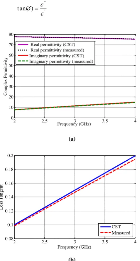
Reconfigurable Antenna for DVB-H Applications,” Electronic Letters, to be published [12] L. Xing, Y. Huang, Q. Xu and S. S. Alja'afreh “Complex Permittivity of Water-based
Liquids for Liquid Antennas,” IEEE Antennas &Wireless Propagation Letters, Under revision
[13] S. S. Alja’afreh, Y. Huang, Q. Xu and L. Xing, “A Hexa-band Metallic Frame Antenna
for Smartphone Applications ”, IEEE Antennas &Wireless Propagation Letters, under peer review.
[14] S. S. Alja’afreh, Y. Huang, Q. Xu and L. Xing, “A Novel Approach for Parasitic
Decoupling Element Design for MIMO Applications”, IET Microwaves Antennas & Propagation, under peer review.
Conference Publications
[1] S. S. Alja’afreh, Y. Huang, L. Xing, “A Compact Dual-Feed Water-Based Diversity
Antenna”, In Proc.LAPC 2013 Conference, November 2013, United Kingdom.
[2] H. T. Chattha, S. S. Alja’afreh, Y. Huang, I Hameed and M. Nasir, “Single Element
Two-Port Planar Inverted-F Diversity Antenna for Wireless Applications”, In Proc. LAPC 2013 Conference, November, 2013, United Kingdom
[3] S. S. Alja’afreh, Y. Huang, L. Xing, “A New Dual-Feed PIFA Diversity Antenna”, In Proc. EuCAP 2014, April, 2014, Netherlands.
[4] S. S. Alja’afreh, Y. Huang, L. Xing, “A Compact Wideband and Low profile Planar
Inverted-L Antenna”, In Proc. EuCAP 2014, April, 2014, Netherlands.
[5] H. T. Chattha, M. Nasir, S. S. Alja’afreh, Y. Huang and A. Sharif, “Modified wideband
Planar Inverted-F Antenna”, In Proc. EuCAP 2014, April, 2014, Netherlands.
[6] S. S. Alja’afreh, Y. Huang, L. Xing, “A Small U-Shaped Dielectric Resonator Antenna ”, In Proc.LAPC 2012 Conference, November 2012, United Kingdom.
Shaped Water Antenna for DVB-H Applications,” In Proc. of the IEEE International Symposium on Antennas and Propagation and USNC-URSI Radio Science, 2014, Tennessee, USA.
[8] L. Xing, Y. Huang, S. S. Alja'afreh, Q. Xu, M. Kod, C. Song, “Reconfigurable 3D
Folded Monopole Antenna Design,” In Proc. LAPC 2014 Conference, November, 2014, United Kingdom.
[9] L. Xing, Y. Huang, Q. Xu, and S. S. Alja’afreh, “Overview of Water Antenna Designs
for Wireless Communications,” accepted by The IEEE 4th Asia-Pacific Conference on Antennas and Propagation (APCAP) 2015.
[10] A. A-B. Sajak, Y. Shen, R. Alrawashdeh, L. Xing and S. S. Alja’afreh, “A
Comparison of the Effect of Substrate on the Performance of THz Antenna,” In Proc. 4th International Conference on Engineering Technology and Techno preneuship (ICE2T) 2014, August, 2014, Malaysia.
[11] S. S. Alja'afreh, Y. Huang, L. Xing, “A Small Wideband U-Shaped Dielectric
Resonator Antenna,” In Proc.LAPC 2012 Conference, November, 2012, United Kingdom. [12] M. Stanley, Y. Huang, H. Wang, S. S. Alja’afreh, Q. Xu and L. Xing, “LTE MIMO
Abstract
Recent evolutions in wireless mobile communications have shown that by
employing multiple inputs and multiple outputs (MIMO) technology at both the transmitter
and receiver, both the wireless system capacity and reliability can be enhanced without the
need for increasing the power transmitted or using more spectrum. Despite a considerable
amount of research have been done on the design of MIMO and diversity handset antennas,
the design of low profile, small footprint and multi-standard (wideband or multiband)
diversity antennas on handset devices remains a challenging issue. Therefore, the purpose of
this thesis is to present new antenna structures for handset MIMO and diversity applications.
As the MIMO antenna design can be conducted either using multiple element antennas
(MEA) or isolated mode antenna technology (IMAT), the work in this thesis is fallen in
these two general design themes (areas).
The first area under investigation concerns multiport antennas (IMAT antennas). It
has the following two contributions:
A novel dual-feed water-based antenna is designed from a low cost liquid material with a very high dielectric constant (pure water
r
81
). The isolationbetween feeds is achieved by two back to back L-shaped ground plane strips. A
prototype is made and the optimised diversity parameters are obtained, the results
show that this design has a good diversity performance over the frequency range
of 2.4 – 2.7 GHz.
A new and low profile (h = 3 mm) planar inverted-F antenna (PIFA) with a coplanar-feed is presented. It has a wideband response over the frequency range
of 2.35 – 3.25 GHz. The design is based on a comparative study on the mutual
coupling between different feed arrangements. As a result, the coplanar feed is
employed in the proposed antenna; the polarization diversity is achieved by
exciting two orthogonal radiation modes. The isolation between the feeds is
achieved by an L-shaped ground plane slot. Both simulated and measured results
demonstrate that the design is a very good candidate for mobile diversity and
MIMO applications.
The second investigation area concerns multiple element antenna (MEA) systems
employed for wideband handset diversity applications over the frequency range of
1.7 – 2.85 GHz: 1) The first design has a dual-element PILA in which both the pattern and spatial diversities are employed; one antenna element is located on the
upper edge of the ground plane while the other is located on the lower edge. 2) The second design represents a more compact dual-element PILA antenna in which the
two elements are placed on the same ground plane edge (collocated on the same
edge). The antenna isolation is achieved using a parasitic decoupling element
inserted between the two elements. A novel approach for the design of the parasitic
decoupling element is proposed. It is based on stepped impedance resonator circuit
theory. As a result, more space is saved with this design (footprint = 385 mm2) over the first design (footprint = 702 mm2). 3) The third design is a four-element PILA system in which two antenna pairs (one pair at the upper edge which the other pair is
located on the lower edge on the system PCB). All the prototypes are made and
evaluated; the results show excellent diversity performance over the applications in
the frequency range of 1.7-2.7 GHz.
A dual-element hexa-band antenna is proposed for smartphone MIMO applications. It consists of two elements: a hexa-band metallic frame antenna and a hepta-band
PILA antenna coupled with a meandered shorted strip as an internal antenna. The
isolation is achieved due to the resulted orthogonal radiation patterns, especially, at
0.85 GHz. The optimized antenna is made and tested and the results show that this
design covers a hexa-band and is particularly suitable for GSM850/ DCS1800/
Chapter 1: Introduction
1.1 Evolution of Mobile Communications
Over the last three decades, the cellular and mobile communication system has been
evolved according to the mobile user’s requirement, market requirement and evolution of the
integrated technology. It started with the first generation (1G) which allowed the mobile
users to make analogue voice communications. In 1990s, the second generation (2G) mobile
services were launched; new mobile services were added in 2G systems such as: digital
voice calls for better quality, data transfer in the form of short message service (SMS) and
later multimedia message service (MMS). Subsequently, 2G evolved into 2.5G with the
introduction of general packet radio systems (GPRS) and higher data rate via higher order
modulation schemes in the mid of 1990s. Then, to meet the increasing demand for more
digital services, the third generation (3G) was introduced. New digital services were
introduced over the existing ones in 2G like a high speed internet access and download
speed, high quality video and voice calls. Currently, the 3G system is updated to the fourth
generation (4G) system by releasing long-term evolution (LTE). It provides a very fast speed
on internet access and a high speed in the downlink channel (up to 100 Mbps) with a high
quality service over severe multipath radio environments. Furthermore, the forthcoming
fifth generation (5G) system aims to support a complex range of communication services
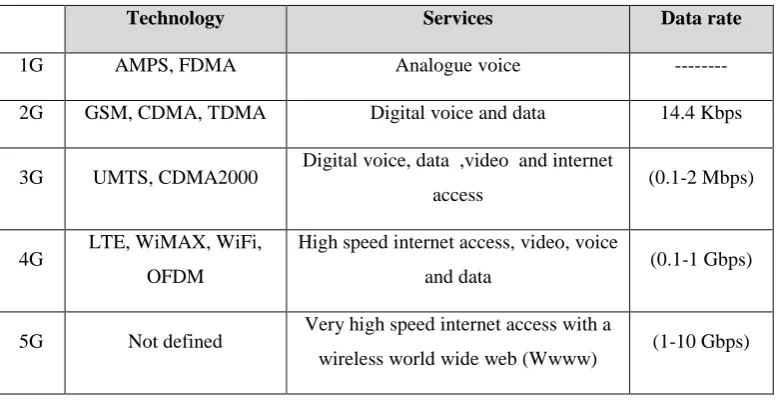
with a tremendous data rate speed up to 10 Gbps. Table 1.1 gives a brief comparative
[image:18.595.126.515.538.739.2]summary about the story of mobile communication system evolutions.
Table 1.1 Brief comparison between the mobile system generations
Technology Services Data rate
1G AMPS, FDMA Analogue voice ---
2G GSM, CDMA, TDMA Digital voice and data 14.4 Kbps 3G UMTS, CDMA2000 Digital voice, data ,video and internet
access (0.1-2 Mbps) 4G LTE, WiMAX, WiFi,
OFDM
High speed internet access, video, voice
and data (0.1-1 Gbps) 5G Not defined Very high speed internet access with a
In conjunction with this development, other wireless systems were integrated and
merged with the recent handset devices (smartphones) such as: wireless local area network
(WLAN), worldwide interoperability for microwave access (WiMAX), global positioning
system (GPS) and Bluetooth. Likewise, the recent 4G systems require high speed
connectivity over long distances with a high grade of service (more reliability). The
conventional solution to increase the system data rate is based on the Shannon-Nyquist
theorem over ideal additive white Gaussian noise channel (AWGN) [1], where the maximum
achievable data rate of a channel with a capacity C, bandwidth W and signal to noise ratio SNR is equal to the capacity of the channel as given in (1.1). It shows that the data rate can
only be increased either by increasing the channel bandwidth or increasing the SNR
(increasing the transmitted power). However, both solutions are unacceptable as the former
means to assign more spectrum bandwidth which is limited and expensive, and the latter
means increasing the power level (increasing interference).
CWlog2
1SNR
[bps] (1.1)Therefore, there is a need in finding another domain to improve the wireless
system data rate. Years ago, the spatial domain has been used in increasing this limit at the
mobile base station end [2, 3]. Increasing demand for higher data rates in the downlink
mobile channel has led to the invention of the MIMO system [4, 5]. By introducing multiple
transmit and receive antennas at both communication ends, the system capacity can increase
with the number of antennas under a certain condition. Recently, MIMO system became one
of the key enabling technologies that are deployed to meet the performance requirement of
the current mobile system [6]. The use of MIMO systems not only increases the data rate
(using spatial multiplexing) but also enhances the system reliability via the spatial diversity
(antenna diversity) system. Finally, as the space is limited in mobile handset devices and the
installation of multiple antennas requires a certain condition like a low level of mutual
coupling,this has attracted more research attention on finding the best antenna configuration
1.2 Evolution of the Mobile Phone Design
The evolution of mobile communications systems has also altered the characteristics
and the functionality of mobile handsets. This was driven by the development of the
integrated circuit technology, the user demands and the newly added services by the mobile
networks. The evolution story can be subdivided into four generations as shown in Fig. 1.1.
1st generation 2nd generation 3rd generation
1983 1997 2003 2007 2015
4th generation
Fig. 1.1: Evolution of mobile phone design
During the 1st generation era (1983-1997), all the handset devices had a ‘‘Candy
bar’’ form factor and the evolution was mainly on reducing of the mobile phone size. A very
few changes had been occurred on the functionality of the mobile phone, it was used only for
voice communications till 1990, then by the development of the 2G system the text
messaging SMS service was added.
Through the end of 1990s, the Clamshell form factor (feature phone) had been
pervaded the mobile market as a new fashion handset. During this era, two interesting
changes were done:1) addition of new features and functionalities like: coloured screen,
taking photos by the added camera, listening to music, sending multimedia messaging
services MMS and introducing to the internet; 2) The miniaturization process reached its
limit as most of handset devices had integrated internal antennas inside them.
By 2003, the miniaturization of the mobile phone was no longer the trend of the
mobile industry; a huge evolution was done with the invention of the smartphone and this
changed the design trend into wide and flat handset devices. Although smartphones have all
the same capabilities of feature phones, they have a common operating system, large screen,
In 2007, the mobile phone industry took a dramatic turn; the touch screen era was
started with the announcement of the iPhone. It had a large coloured touch screen display
and its user interface was finger-friendly. Consequently, this increases the competitions
between the handset designers to find and employ the cutting-end technologies.
1.3 Evolution of Handset Antennas
As discussed in Section 1.1, the last three decades have witnessed a phenomenal
growth in the wireless communication technology. This evolution was reflected on the
mobile phone design. However, all these evolutions would not have been existed without a
development on handset antennas. The evolution of handset antennas was governed by user
demands (cosmetic and compactness issues) and by technical requirements like changing the
design trend from a single band in the 1G to a dual band in the 2G and then to multiband
designs in the 3G and 4G. Moreover, the latest evolution of the wireless technology also led
to the emergence of a new antenna design trend which is the multi-element antenna design
for MIMO and diversity applications.
In this section, the commonly used antenna structures on mobile phones are
discussed in terms of three eras of antenna designs: external antennas, internal antennas and
hybrid antennas (combination of external and internal antennas). A detailed review about the
development of mobile phone antennas can be found in [7].
1.3.1 External Antennas
Prior to 1997, all mobile phones had an external antenna on the top of the mobile
housing [8]. The oldest type was the Whip monopole as shown in Fig. 1.2; it was used
widely during the 1G mobile systems as a single band design. Unfortunately, this antenna
was quite large as it had to be extended when the phone was in use so this was making it
susceptible to breaking and damaging. To overcome this problem, inductive loading had
been employed to shorten the length of handset antennas, the solution was named as a helical
antenna, which is a simple conductor wire wound into a helix shape and enclosed in a plastic
rubber [9]. With the introduction of the 2G mobile technology, a newly added high
frequency band was allocated for mobile applications; this led to the need for a dual band
whip antenna passing through the helix axis. However, this solution had a difficulty in fixing
the whip monopole inside the helix. The most powerful solution that was being used widely
is the dual-band helix antenna; it has different pitch for dual band feature as shown in Fig.1.
3 [10]. Although external antennas had excellent bandwidth and efficiency, they had a high
specific absorption rate (SAR) that exceeded the FCC limit.
Fig. 1.2: First mobile phone with external Whip antenna
[image:22.595.260.413.202.388.2]
1.3.2 Internal Antennas
By the end of 1990s, Nokia 3210 shown in Fig.1.4 entered the market as the first
mobile phone with an internal antenna. After that, internal antennas began to gain more
popularity than external antennas. Different antenna structures have been used as internal
antennas. Due to its attractive features like: simple design, light weight and low cost planar
inverted-F antenna (PIFA) is the most commonly used [11]. Usually, it is defined as a
shorted patch or microstrip antenna. As multiband antennas are highly needed in mobile
phones, different techniques have been employed to evolve PIFA into a multiband operation.
Such techniques like: creating slit cuts in the patch to alter the current paths [12], using
grounded parasitic elements in a region of high electric field strength [13], creating ground
plane slots underneath PIFA [14], a combination of patch slots and parasitic elements [15,
16], and a combination of ground plane slots and patch slots [17-19].
As the design trend of mobile phones was focused on the miniaturization, the
preferable place for internal antennas was the top of the mobile phone. This led to neglect the
use of other antenna structures (planar monopoles and slot monopole antennas) that produce
a high SAR value due to the cleared ground plane area underneath them. These structures
received great research attentions after the releasing of the Motorola Razor in 2004 [20], a
folded monopole antenna was used on the bottom of the mobile phone. The success of the
Razor started the new trend for the ultra slim phone using printed monopoles [21-26] and
[image:23.595.261.412.515.708.2]slot antennas [27, 28].
Recently, the design of handset antennas became challenging due to the added new
frequency bands which increased the need for multi-broadband antenna solutions [29]. The
conventional antennas like PIFA and planar monopoles are difficult to adjust their
impedance bandwidth in a multi-broadband between 700 MHz and 3.8 GHz. Also, these
antenna structures usually excite a large surface current on the system ground plane which
acts as a part of the radiator and this increases the SAR effect and antenna detuning by
biological bodies [30, 31]. As the loop antenna excites a small amount of surface current on
the system ground plane and the broadband impedance bandwidth can be achieved by
merging different loop modes together [29], loop antennas received a considerable attention
from researchers in both the academic field and the mobile industry [29-32]. Another
successful story with loop antennas is initiated after releasing iPhone 4 in 2010 [33, 34].
Further details are presented in the next section.
1.3.3 Hybrid Combination of External and Internal
Antennas (Metallic Frame Antennas)
In 2010, Apple Inc. released iPhone 4 which was the first smartphone with a metallic
frame house. The interesting thing from this product was the hidden function of the metal
frame. Apple used both external antennas and internal antennas to find a hybrid type of
antenna. This hybrid antenna consists of a metallic frame (as external antenna) casing the
mobile chassis around the perimeter and it is coupled with a loop antenna as an internal
antenna which is fed directly from the gap as shown in Fig. 1.5 [34]. After this, the idea has
been propagated through the whole industry of the mobile market. Moreover, recent years
have witnessed a lot of research publications about this new era of the antenna design for
mobile phones [35-42]. Table 1.2 summarizes and compares the basic antenna structures
(a)
[image:25.595.170.507.91.588.2](b)
Fig. 1.5: Hybrid antenna (a) Schematic diagram [34] and (b) iPhone 4, the first mobile
phone with a metallic frame antenna
Table 1.2 Comparison of mobile phone antenna types
Type Theory Advantages Disadvantages
External Antennas
Whip /4 antenna
Excellent impedance bandwidth, east to
manufacture
Poor performance, large especially at the extended mode, susceptible to
breaking and damage, to achieve multiband is not easy
Helix 4 / 8 / antenna (with inductive loading)
Short size, good impedance bandwidth and easy to
manufacture
High SAR
Internal Antenna [7]
Slot /4 or /2 slot Not sensitive to detuning SAR is high for slot monopole antennas
Ceramic
Antennas
4 /
monopole type ceramic antenna, DRA antenna 30 10
Small and compact Narrow bandwidth, fragile material
PIFA /4 shorted
microstrip antenna
Low SAR, easy to design, light weight, simple design
Narrow bandwidth, 3D structure (some designs are high profile)
Printed Monopole antennas 2 / 4 /
planar antenna without ground underneath
Very low profile (slim antenna), light weight, simple
design
High SAR
Hybrid Antenna (Metal Frame Antenna)
Metal
Frame with
Gaps
Metallic frame coupled with internal loop or
slot antenna
Multiband design, add nice cosmetic appearance
High detuning due to gaps in the frame, high SAR if the feeding
point is near the gap
Closed Ring
Metal
Frame
Loop Antenna formed from both metal frame and the system PCB.
Multiband design, add nice cosmetic appearance
1.4 Current Challenges in Handset MIMO Antenna
Design
Despite of the aforementioned developments that have occurred on the cellular
mobile communication technology, several system’s design challenges are appeared. In
regard to the handset antenna design, the following challenges are appeared:
1) Universal and compact mobile antenna: By the releasing of the new LTE 4G
frequency bands, the wireless spectrum of the current 2G, 3G and 4G systems
are scattered between 700 MHz to 3800 MHz as shown in Fig. 1.6. Also, other
wireless systems likes GPS, WiFi, Bluetooth and WiMAX are now integrated
with recent Smartphone devices. All these increase the need for universal
(multi-standard) handset antenna (wideband or multiband antennas) without increasing
the volume occupied for antenna integration [43].
MHz 698 824 960 1427 1496 1710 2170 2300 2690 3300 3800
4G
3G
Fig. 1.6: Radio spectrum for 3G and 4G applications
2) Multiple antenna system (MIMO antenna): As the MIMO system represents
one of the recent important technologies that are deployed to meet the current
performance requirements in 3G and 4G systems. The 4G system (advanced
LTE) has set the peak data rate up to 1 Gbps for low mobility scenarios and up
to 100 Mbps for high mobility cases. Therefore, to deploy this in the current
technology, it requires a number of antenna elements to be installed at both
wireless communication ends. Subsequently, the biggest challenge lies in the
integration of multiple antennas into a small handset device, especially, for
applications below 1GHz; antenna elements are closely spaced in terms of the
wavelength and the common ground plane will act as a main radiator, thus, the
antennas tend to be more correlated (coupled). The high level of correlation
affects and destroys all the performance parameters of the MIMO and diversity
system, as an example, the antenna efficiency becomes worse and the system
3) Upcoming 5G and massive MIMO: The next generation (5G) system is
expected to be started in 2020; the expected throughput will be between 1-10
Gbps. It tends to provide unlimited, fast and huge access to information at
anytime and everywhere in the world, high traffic capacity, short latency time,
data integrity [44]. Thus, it will require a massive upgrade on the existing
technology tools. As an example, the existing utilized radio spectrum will be
extended to higher microwave frequency bands (above 10 GHz) and even to
millimeter wave frequencies (above 60 GHz). All of these will add some
challenges regarding the design of antenna systems. A massive MIMO antenna
system (large number of antenna elements) is to be installed at both the mobile
station and the base station. Table 1.2 gives a clear view on the upcoming MW
massive MIMO and mm-Wave MIMO. On the other hand, one of the antenna
design challenges for 5G will be on the material of the antenna; at the higher
microwave frequency bands and the millimeter wave frequencies, both the
substrate loss and the metal loss will increase.
Table 1.2 Massive MIMO schemes [44]
Microwave
(1-30 GHz)
Millimeter Wave
(30- 300 GHz)
Bandwidth 20-50 MHz >256 MHz # of antennas @ BS 32-64 64-256
# of antennas @ MS 1-4 4-12
Beamforming Digital Analogue
1.5 Research Motivation
Although much research has been conducted on the design of mobile phone
antennas, there is a continuous demand for finding antenna solutions to meet the current and
future wireless technology generations. As an example, the avenue of designing compact
multi-element antennas or multi-port antennas for small, slim and multi-standard mobile
handsets is an interesting area of research [44-47]. Therefore, this work has two general
themes: the first one is to find single element MIMO antennas with a multi-feed for mobile
phone applications, while the second one is to find multi-element MIMO antennas for either
wideband or multiband mobile handset applications. Keeping in the mind the recent
requirement for the design of handset antennas like: low profile, compact and for
multi-standard use.
Over the last three decades, dielectric resonator antennas (DRAs) have received a
great research attention [48]. However, most of the proposed DRA designs were only used
dielectric materials that have moderate dielectric constants [49, 50]. Only very few works
utilized very high dielectric constant materials [51, 52]; and this is mainly due to their high
cost and the resulting narrow bandwidth. Interestingly, in the area of MIMO and antenna
diversity technology, there is no work presented DRA with a very high dielectric constant in
small handheld devices, even the existing MIMO DRA designs are only with
equally-dimension structures like cylindrical and cube shape [53-55]. As a low cost material with a
very high dielectric constant, pure water (
r
81
) has received a great research attention inthe recent years [56, 57]. In this thesis, the focus is on finding a water based antenna for
MIMO and diversity handset applications.
The planar inverted-F antenna (PIFA) is one of the most preferable antenna
structures in the design of efficient and low profile handset antennas [8, 11]. However, most
of the proposed works on PIFA were mainly single element designs [12-19], even the MIMO
designs; some of them use the spatial diversity to achieve the isolation condition [58]. Few
works used PIFA with a multi-feed to save a space in small handset terminals [59-61], but all
of them suffer from several drawbacks like: high antenna profile, narrowband operation and
impractical use for the integration [59-61]. Therefore, the second motivation of this work is
focused on finding a very low profile, wideband, dual-feed PIFA antenna for handset
diversity applications.
PILA is one of the first low profile antenna structures [8, 11]. However, its mismatch
designers to solve its mismatching problem; the conventional solution was to evolve PILA
into PIFA which was simply by adding another shorted-L plate next to the feeding point
[11]. Other solutions like: modifying of the antenna feed using a dielectric resonator antenna
(DRA) as a feed [62], modifying the top plate [63], however, there is no work dealt with the
interaction between the PILA top plate and the ground plane underneath. Also, the presented
work in [64] which deals with the interaction between the handset antenna and the ground
plane guided this research to solve PILA problem. Therefore, this work proposes a
wideband, low profile PILA for mobile applications in the frequency range from 1.7 to 2.85
GHz. Then, the PILA is adopted as a MIMO and diversity antenna using several designs.
In the recent years, smartphones have entered mobile markets and have enjoyed a
rapid growth. As an example, the current trend in designing smartphones is to use a metallic
frame in the housing [24]. One of the big advantages of the metallic frame lies in using it as
a part of the antenna circuitry [34]. However, some of the proposed antenna solutions using
this new trend were focused on the design of metallic frame antenna as a single element
design, and they did not pay attention on finding MIMO solutions especially for applications
below 1 GHz [65, 66]. Interesting design solutions have been reported in [67, 68], a new
characteristic mode (orthogonal to the conventional chassis dipole mode below 1 GHz) has
been excited by a metal frame antenna. This facilitated the introduction of a dual-element
antenna for MIMO applications. However, these proposed solutions are high profile designs
and can only cover single band [67] or dual band [68]. The final motivation for this work
leads to develop a new multiband metal frame antenna, which is integrated with an internal
multiband antenna to form a dual-element multiband antenna for MIMO and diversity
1.6 Organization of the Thesis
The rest of the thesis is organized as follows:
Chapter 2 discusses MIMO system and its signalling techniques. Then, it discusses
the antenna diversity system in detail such as: the types of the diversity techniques, the
diversity combining techniques, the MIMO decoupling techniques and the diversity gain.
Furthermore, this chapter presents the measurement techniques that are used to characterize
all MIMO designs in the rest of the thesis.
Chapter 3 introduces two water-based antenna designs for Bluetooth, 2.4 GHz WiFi
and three LTE bands (bands 7, 38 and 41). The first one represents a single feed antenna,
while the second one is a dual-feed design. Both designs are fabricated and tested.
Chapter 4 concerns another dual-feed antenna design. It presents a new design of
low profile, wideband PIFA antenna for handset diversity applications over the frequency
range of (2.35-3.25 GHz). The antenna utilizes a new feed arrangement that maintains a low
mutual coupling level compared to the other feed arrangements. Based on the optimized
design parameters, the antenna is made, tested and the results are reported in Chapter 4.
Chapter 5 deals with two designs of a low profile planar inverted-L antenna (PILA)
for wideband handset applications in the frequency range of (1.7-2.85 GHz). After finding a
single-element PILA, two elements are arranged utilizing both pattern and spatial diversities
to provide a reasonable isolation level.
Chapter 6 continues the story of Chapter 5, a more compact dual-element PILA
antenna (collocated on the top edge of the PCB) is presented, the compactness is achieved
using a parasitic decoupling element that is designed and optimized based on the stepped
impedance resonator (SIR) circuit theory. This chapter also includes a four-element PILA
design that comprises two elements on the top edge of the ground plane PCB while the other
two elements are on the lower edge. For both designs, the evaluation metrics provided in
chapter 2 are all presented and discussed.
Chapter 7 describes a new design of a multiband metal frame antenna for
smartphones applications. This metal frame antenna is also integrated with an internal
antenna (PILA and a meandered strip that is shorted to a ground plane). The resulting
dual-element antenna is presented for multiband handset applications, such applications like:
GSM850/ DCS1800/ PCS1900/ UMTS2100/ LTE2500/ LTE3600.
References
[1] C. E. Shannon, “A mathematical theory of communication,” Bell Syst Tech., vol. 27, pp. 379-423, 623-656, July & Oct. 1948.
[2] J. Winters, “On the capacity of radio communication system with diversity in a
Rayleigh fading environment,” IEEE Journal on Selected Areas in Communications., vol. 5, no. 5, pp. 871-878, June. 1987.
[3] R. G. Vaughan and J. B. Anderson, “Antenna diversity in mobile communications,”
IEEE Trans.Veh. Thecnol., vol. VT-36, no. 4, pp. 149-172, Nov. 1987.
[4] G. J. Foschini, “Layered space-time architecture for wireless communication in a
fading environment when using multi-element antennas,” Bell Lab Tech J., vol. 1, no. 2, pp. 41-59, 1996.
[5] G. J. Foschini and M. J. Gans, “On limits of wireless communications in a fading
environment when using multiple antennas,” Wireless Personal Communications., pp. 311-335, Mar. 1998.
[6] 3rd Generation Partnership Project; Technical Specification Group Radio Access Network; Evolved Universal Terrestrial Radio Access (E-UTRA) Radio Resource Control; Protocol Specification, 3GPP TS36.331, v8.4.0, 2008.
[7] C. Rowell and E. Y. Lam, “Mobile –phone antenna design,” IEEE Antennas and Propagation Magazine., vol. 54, no. 4, pp. 14-34, August 2004.
[8] Z. N. Chen, Antennas for portable devices, John Wiley & Sons, 2007.
[9] K. Fujimoto and J. R. James, Mobile antenna system handbook, Norwood USA, Artech House, 2nd Edition, 2001.
[10] Z. Ying, “Some important antenna innovations in the mobile terminal industry in the last decade,” Nordic Antenna Symposium., Sweden, June. 2006.
[11] Y. Huang and K. Boyle, Antennas: from theory to practice, John Wiley & Sons, 2008.
[12] Z. Li, Y. Rahmat-Samii and T. Kaiponen, “Bandwidth study of a dual band PIFA on
a fixed substrate for wireless communication,” Antennas and Propagation Society International Symposium., USA, 2003.
[13] P. Song and P. S. Hall and H. G. Shiraz and D. Wake, “Triple-band planar inverted F
[14] R. Hossa, A. Byndas and M. E. Bialkowski, “Improvement of compact terminal
antenna performance by incorprating open-end slots in ground plane,” IEEE Microwave and Wireless Component Letters., vol. 14, no. 6, June, 2004.
[15] P. Ciais, R. Staraj, G. Kossiavas, and C. Luxey, “Design of an internal quad-band
antenna for mobile phones,” IEEE Microwave and Wireless Components Letters.,
vol. 14, no. 4, pp. 148-150, 2004.
[16] P. Ciais, R., C. Luxey, A. Diallo, R. Starag and G. Kossiavas, “Penta band internal
antenna for handset communication devices,” Microwave and Optical Technology Letters., vol. 48, no. 8, pp. 1509-1512, 2006.
[17] M. F. Abedin, M. Ali, “Modifying the ground plane and its effect on planar
inverted-F antennas (PIinverted-FAs) for mobile phone handsets,” IEEE Antenna Wireless Propag. Lett., vol. 2, pp. 226-229, 2003.
[18] A. Cabedo, J. Anguera et al., “Multiband handset antenna combining a PIFA slots,
and ground plane modes ,” IEEE Trans. Antennas Propag., vol. 57, no. 9, pp. 2526-2533, 2009.
[19] J. Anguera, I. Sanz et al., “Multiband handset antenna with a parallel excitation of
PIFA and slot radiators ,” IEEE Trans. Antennas Propag., vol. 58, no. 2, pp. 348-356, 2010.
[20] Z. Zhang, Antenna design for mobile devices, John Wiley & Sons, 2011.
[21] T. Zhang, R. Li et al., “A novel multiband planar antenna for GSM/ UMTS/ LTE/
Zigbee/ RFID mobile devices ,” IEEE Trans. Antennas Propag., vol. 59, no. 11, pp. 4209-4214, Nov. 2011.
[22] Y. L. Ban, G.H. Chen et al., “Low-profile printed octa-band LTE/WWAN mobile
phone antenna using embedded parallel resonance structure ,” IEEE Trans. Antennas Propag., vol. 61, no. 7, pp. 3889-3894, July. 2013.
[23] K.C. Lin, C. H. Lin et al., “Simple printed multiband antenna with novel
parasitic-element design for multistandard mobile phone applications ,” IEEE Trans. Antennas Propag., vol. 61, no. 1, pp. 488-491, Jan. 2013.
[24] Y. L. Ban, G. H. Chen et al., “Small-size printed coupled-fed antenna for eight-band
LTE/GSM/UMTS wireless wide area network operation in an internal mobile handset,” IET Micro. Antennas Propag., vol. 7, no.6, pp. 399-407, March. 2013. [25] S. Wang, Z. Du, “A compact octaband printed antenna for mobile handsets,” IEEE
[26] H. Liu, R. Li et al., “A multi-broadband planar antenna for GSM/UMTS/LTE and WLAN/WiMAX handsets,” IEEE Trans. Antennas Propag., vol. 62, no. 5, pp. 2856-2860, May. 2014.
[27] C. I. Lin and K. L Wong., “Printed monopole slot antenna for internal multiband
mobile phone antenna,” IEEE Trans. Antennas Propag., vol. 55, no. 12, pp. 3690-3697, Dec. 2007.
[28] H. W. Hsieh, Y. C. Lee et al., “Design of multiband antenna for mobile handset operations,” IEEE Antenna Wireless Propag. Lett., vol. 8, pp. 200-203, 2009.
[29] K. L. Wong, C. H. Huang, “Printed loop antenna with a perpindicular feed for
penta-band mobile phone application,” IEEE Trans. Antennas Propag., vol. 56, no. 7, pp. 2138-2141, July 2008.
[30] Y. W. Chi, K. L. Wong, “Internal compact dual-band printed loop antenna for
mobile phone application,” IEEE Trans. Antennas Propag., vol. 55, no. 5, pp. 1457-1462, May 2007.
[31] X. Zhang, W. Wu et al., “Seven band surface-mount loop antenna with a
capacitively coupled feed for mobile phone application,” Microwave and Optical Technology Letters., vol. 51, no. 1, pp. 81-88, January 2009.
[32] C.-W. Chiu, C.-H. Chang, “Multiband folded loop antenna for smartphones,”
Progress in Electromagnetic Research., vol. 102, pp. 213-226, 2010.
[33] Z. Zhang, R. J. Hill, R. W, Schlub, J. Zavala and R. Caballero,“Hybrid antennas with
directly fed antenna slots for handheld electronic devices,” U.S. Patent 7551142, June. 23, 2009.
[34] M. Pascolini, R. J. Hill, J. Zavala, N. Jin, Q. Li, R. W. Schlub and R.
Caballero,“Bezel gap antennas,” U.S. Patent 8270914, Sept. 18, 2012.
[35] J. Zhong, K.-K. Chen and X. Sun, “A novel multi-band antenna for mobile phone
with metal frame,” 8th Internaltional Conference on Wireless Communication, Networking and Mobile Computing (WiCOM)., China, Sept. 2012.
[36] Q. Gua, R. Mittra et al., “Interaction between internal antenna and external antenna
of mobile phone and hand effect,” IEEE Trans. Antennas Propag., vol. 61, no. 2, pp. 862-870, Feb. 2013.
[37] Z. Miers, H. Li et al., “Design of bandwidth-enhanced and multiband MIMO
[38] Y.-L. Ban, Y.-F. Qiang et al., “Low-profile narrow-frame antenna for seven-band
WWAN/LTE smartphone applications,” IEEE Antenna Wireless Propag. Lett., vol. 13, pp. 463-466, 2014.
[39] L. W. Zhang and Y. L. Ban, “A novel hepta-band coupled-fed antenna for
WWAN/LTE metal-ring-frame smartphone applications,” Progress in Electromagnetic Research Symposium (PIERS)., China, Aug. 2014.
[40] H. Li, Z. Miers et al., “Design of orthogonal MIMO handset antennas based on
charactrestic mode manipulation at frequency band below 1 GHz,” IEEE Trans. Antennas Propag., vol. 62, no. 5, pp. 2756-2766, May. 2014.
[41] S. Eom, H. Kim et al., “Embedded antenna for metallic handheld communication
devices,” Progress in Electromagnetics Research B., vol. 57, pp. 127-138, 2014. [42] Y.- L. Ban, Y.- F. Qiang et al., “A dual-loop antenna design for hepta-band
WWAN/LTE metal-rimmed smartphone applications,” IEEE Trans. Antennas Propag., vol. 63, no. 1, pp. 48-58, Jan. 2015.
[43] B. K. Lau and Z. Ying, “Antenna design challenges and solutions for compact
MIMO terminals,” International Workshop on Antennas Technology (iWAT)., Hong Kong, March. 2011.
[44] http://www.ieee-ctw.org/2014/slides/session3/Heath-CTW_v6.pdf, [10 Aug 2015]. [45] Z. Ying, “Antennas in cellular phones for mobile communications,” Proceeding of
TheIEEE., vol. 100, no. 7, pp. 2286-2296, July. 2012.
[46] H. Wong, K.-M. Luk et al., “Small antennas in wireless communications,” Proceeding of TheIEEE., vol. 100, no. 7, pp. 2109-2121, July. 2012.
[47] J. Anguera, A. Andujar et al., “Advances in antenna technology for wireless
handheld devices,” International Journal on Antennas and Propagation., vol. 2013, Articale ID: 838364, 2013.
[48] A. Petosa, and A. Ittipiboon, “Dielectric Resonator Antennas: A Historical Review
and the Current State of the Art,” Antennas and Propagation Magazine, IEEE, vol. 52, no. 5, pp. 91-116, 2010.
[49] L. Huitema, M. Koubeissi, C. Decroze, and T. Monediere, “Ultrawideband dielectric
resonator antenna for DVB-H and GSM applications,” IEEE Antennas and Wireless Propagation Letters, vol. 8, pp. 1021-1024, 2009.
[50] T-H. Chang, Y-C. Huang, W-F. Su and J-F. Kiang, “Wideband dielectric resonator
[51] G. Bit-Babik, C. Di Nallo, and A. Faraone. “Multimode dielectric resonator antenna
of very high permittivity,” IEEE Antennas and Propagation Society International Symposium, 2004.
[52] M. Rotaru and J. K, Sykulski, “Numerical Investigation on Compact Multimode
Dielectric Resonator Antennas of very High Permittivity,” Science, Measurement & Technology, IET, vol. 3, no. 3, pp. 217-228, 2009.
[53] K. Ishimiya, J. Takada, Z. Ying, "A Compact MIMO DRA Antenna.", International workshop on antenna technology. IWAT 2008, pp. 286-289.
[54] C. Oikonomopoulos-Zachos, and B. Rembold, "A 4-Port Antenna for MIMO
Channels.", EuCAP 2007, pp. 1-4.
[55] L. Z. Thamae, and Z. Wu, “Diversity performance of multiport dielectric resonator
antennas,” Institution of Engineering and Technology, vol. 4, no. 11, pp. 1735-1745, Nov.2010.
[56] Y. Li and K.-M. Luk, “A Water Dense Dielectric Patch Antenna,” IEEE Access, vol. 3 pp. 274-280, April, 2015.
[57] L. Xing, Y. Huang, Y. Shen, S. ALja’afreh et al, “Broadband U-Shaped Water
Antenna for DVB-H Applications,” In Proc. IEEE Antennas and Propagation Society International Symposium, pp. 1930-1931, July, 2014.
[58] M. Karaboikis, C. Soras et al., “Compact dual-printed inverted-F antenna diversity systems for porable wireless devices,” IEEE Antenna Wireless Propag. Lett., vol. 8, pp. 9-14, 2009.
[59] H. T. Chattha, Y. Huang, S. J. Boyes et al., “Polarization and pattern diversity-Based
dual-feed planar inverted-F antenna,” IEEE Transactions on Antennas and Propagation, vol. 60, no. 3, pp. 1532-1539, 2012.
[60] H. T. Chattha and Y. Huang, “Low profile dual-feed planar inverted-F antenna for
wireless LAN applications,” Microwave Optical Technology Letters, vol. 53, pp. 1382–1386, 2011.
[61] H. T. Chattha, Y. Huang and X. Zhu, “Dual-feed PIFA diversity antenna for wireless applications,” Electronics Letters, vol. 46, no. 3, pp. 189-190, 2010.
[62] Y. F. Lin, H. M. Chen, C. Y. Lin, et al., “Planar inverted-L antenna with a dielectric
resonator feed in a mobile device,” IEEETrans. Antennas Propag., vol. 57, no. 10, pp. 3342-3346, 2009.
[64] J. Anguera, A. Andujar and . Garcia, “Multiband and small coplanar antenna system
for wireless handheld devices,” IEEE Trans. Antennas Propag., vol. 61, no. 7, pp. 3782-3789, 2013.
[65] S. Eom, M. Ali, S. O. Park and H. Kim, “Embedded antenna for metallic handheld
communication devices,” Progress in Electromagnetics Research B., vol. 57, pp. 127-138, 2014.
[66] Y. L. Ban, Y. F. Qiang et al, “A dual-loop antenna design for hepta-band
WWAN/LTE metal-rimmed smartphone applications,” IEEE Trans. Antennas Propag., vol. 63, no. 1, pp. 48-58, 2015.
[67] H. Li, Z. Miers and B. K. Lau., “Design of orthogonal MIMO handset antennas
Based on characteristic mode manipulation at frequency bands below 1 GHz,” IEEE Trans. Antennas Propag., vol. 62, no. 5, pp. 2756-2766, 2014.
[68] Z. Miers, H. Li and B. K. Kiong., “Design of bandwidth-enhanced and multiban
MIMO antennas using characteristcs modes,” IEEE Antenna Wireless Propag. Lett.,
vol. 12, pp. 1696-1699, 2013.
Chapter 2: MIMO Antenna Systems
The introduction of MIMO technology has revolutionized wireless communications
over the past decade. Multiple antenna systems are now used at the base station, and have
also received a great research attention in the design of compact mobile phones. This chapter
starts with an overview about MIMO system; only two important MIMO techniques (spatial
multiplexing and spatial diversity) are described with their benefits on the wireless system
performance. The third MIMO technique which is called beamforming is not considered as it
addresses the signal processing rather than antenna design. Then, as this thesis is focused on
the MIMO antenna design based on diversity scheme, mainly on the antenna diversity, the
mechanism of antenna diversity, the diversity combining techniques, diversity performance
parameters and the decoupling techniques are only discussed and presented in more detail.
Also, some of the experimental works of the measurement of both diversity gain and total
radiation efficiency are summarized.
2.1 MIMO Systems
The conventional wireless communication system usually uses one antenna element
at both the transmitter and the receiver; this system is called single input single output
(SISO) system as shown in Fig. 2.1. Although this system is very simple (usually it does not
need advanced signal processing), but the received signal quality (SNR) from a severe radio
multipath channel is usually an attenuated version of the transmitted one, which makes the
system reliability very poor. Also, based on the Shannon-Nyquist criterion [1]; the
throughput of SISO depends on both the received signal to noise ratio and the channel
bandwidth (usually narrowband). This adds a difficulty in the receiver side to get more data
throughput and more reliability.
To enhance the wireless system reliability and to reduce impact of fading, antenna
diversity was the effective technique that has been used widely. SISO system was evolved to
a single input multiple output (SIMO) system by introducing the receive diversity in 1931 [2,
3], it has been applied in different wireless applications for more than 70 years [4]. By the
beginning of 1990s, a new type of multi-antenna techniques was developed by [5], this
technique was used transmit diversity to develop a multiple input single output (MISO)
system; it has been deployed in the 2G mobile system to enhance the radio coverage of base
(a)
(b)
Transmitter 1 1 Receiver
Channel
1 Rx Antenna
(Output) Channel
h = h11
1
Tx Antenna (Input)
Fig. 2.1: (a) Single input and single output (SISO) system and
(b) SISO from channel perspective
In the late of 1990s, a great breakthrough in the wireless communication system has
been conducted with the introduction of the MIMO technology by Foschini [6, 7]. Foschini
and his research group not only used spatial diversity to combat the fading, they developed a
new way of exploiting fading (spatial multiplexing) to support and enhance the throughput
capacity [5]. Since these initial breakthroughs, MIMO technology has been adopted in
different commercial wireless applications and standards like: WiMAX in 2005, 4G LTE
mobile systems in 2010. Also, both spatial diversity and spatial multiplexing became the
most important landmarks and techniques of this new wireless technology (MIMO).
In a MIMO system both the transmitter and the receiver need multiple antenna
elements; Fig. 2.2 represents a MIMO system with an M transmit antennas and N receive
antennas. It can be seen that the channel response is no longer described by the single
channel response as in the case of SISO (see Fig. 2.1(b)); the channel response is now
described by a channel matrix H as expressed in Fig. 2.2(b), where hij is the complex
[image:39.595.187.489.91.320.2](b) 1 2 Transmitter M 1 2 Receiver N h11 h22 hNM h21 h12
h1M
hN1 h2M h2N
1 Rx Antennas (Output) 1 Tx Antennas (Input) 2 M 2 N NM N N M M h h h h h h h h h 2 1 2 22 21 1 12 11 Channel (a)
Fig. 2.2: (a) Multiple input multiple output (MIMO) system and
(b) MIMO from channel perspective
2.1.1 Spatial Multiplexing and Channel Capacity
Spatial multiplexing (SM) is one of the most important MIMO techniques. It
transmits multiple parallel data streams in multiple data channels over the same frequency
band and time slot. One of the most important feature of this technique over other
multiplexing techniques (frequency division multiplexing (FDM), time division multiplexing
(TDM) and code division multiplexing (CDM)) is that it does not suffer from bandwidth
expansion because of assigning multiple signals to different spatial channels [4]. To
demonstrate the basic principle of SM, Fig. 2.3 shows a MIMO system with 2×2 elements.
As shown, the data bit stream is transformed into parallel sub-streams via serial to parallel
(S/P) converter, then the sub-streams are modulated and transmitted simultaneously from
each transmit antenna element. If the antennas at both transmitter and receiver are separated
far apart,; this means that the propagated channels are uncorrelated and thus the received
signals are well separated at the receiver side. After demodulating the original sub-streams,
[image:40.595.185.484.100.334.2]S1 = 10
S2 = 11
S /P c o n v e rt e r
1011
Input bit
stream
h12 h21
h22 h11 P /S c o n v e rt e r
Output bit
stream
Transmitter
Receiver
Fig. 2.3: MIMO with spatial multiplexing
Therefore, the SM increases the channel capacity with increasing the number of
transmit and receive antennas [6, 7]. For a general case of MIMO system like in Fig. 2.2,
with the number of transmit elements M and the number of receive elements N, the
maximum number of parallel pipes (data streams) will be:
N
max
min(
M
,
N
)
(2.1)The resulting channel capacity using SM depends on whether the transmitter has
information about the channel state or not, the simplest case which is the case with no
information is only discussed. If the channel state is not known at the transmitter, then the
transmitter will power all the antennas equally and the resulting channel capacity is [7]:
N
H
H
H
M
I
C
log
2det
.
[bit/sec/Hz]
(2.2)
where denotes the average signal to noise ratio (SNR) at each receiver; det is the determinant operator; IN denotes the identity matrix and H is the normalized channel matrix
of N × M size.
The very interesting benchmark of this technique lies on the exploiting the multipath
phenomena in increasing the channel capacity; both the multipath and scattering are very
important for SM to work efficiently. This can be shown from Eq (2.3) after applying the
eigenvalue decomposition on H.HH and substituting in Eq (2.2)
ir
i
M
C
1 2
![Fig. 1.3: Dual band non-uniform helix antenna invented by Z. Ying [10].](https://thumb-us.123doks.com/thumbv2/123dok_us/8064826.226522/22.595.260.413.202.388/fig-dual-band-uniform-helix-antenna-invented-ying.webp)

![Fig. 1.5: Hybrid antenna (a) Schematic diagram [34] and (b) iPhone 4, the first mobile](https://thumb-us.123doks.com/thumbv2/123dok_us/8064826.226522/25.595.170.507.91.588/fig-hybrid-antenna-schematic-diagram-b-iphone-mobile.webp)


![Fig. 2.14: Neutralization line between two PIFA antennas [72].](https://thumb-us.123doks.com/thumbv2/123dok_us/8064826.226522/63.595.195.472.267.468/fig-neutralization-line-pifa-antennas.webp)
![Fig. 2.15: Isolation using parasitic decoupling element [75].](https://thumb-us.123doks.com/thumbv2/123dok_us/8064826.226522/64.595.201.466.101.319/fig-isolation-using-parasitic-decoupling-element.webp)