CFD Simulation of Vortex-Induced Vibration of a Vertical Riser
Enhao Wang, Qing Xiao
1, Atilla Incecik
Department of Naval Architecture, Ocean and Marine Engineering, University of Strathclyde, Glasgow G4 0LZ, UK
Abstract: Three-dimensional fluid-structure interaction (FSI) simulations are conducted on a vertical riser with
a length-to-diameter ratio L/D = 481.5. Important vortex-induced vibration (VIV) parameters including the
amplitude responses, orbital trajectories, oscillation frequencies and vorticity contours are presented. The
computational fluid dynamics (CFD) simulation results are in good agreement with published experimental
data. The riser exhibits a dual-resonant response. Two different vortex shedding mode is observed, i.e., 2P and
2S modes. 2P mode is associated with the maximum transverse amplitude and 2S mode is observed elsewhere
along the riser.
Keywords: vortex-induced vibration (VIV), Computational Fluid Dynamics (CFD), fluid-structure interaction
(FSI), vertical risers, uniform flow
1. Introduction
Vortex-induced vibration (VIV) is a major cause of fatigue
failure in offshore slender structures. The reliable estimation
of the fatigue damage of risers and mooring lines requires
detailed understanding and efficient prediction of these
self-excitation and self-sustained oscillations.
Fig. 1 Sketch of the physical configuration.
Over the past few decades, VIV has been extensively
studied. For detailed information, one may refer to the
1
Corresponding author email: [email protected]
review papers by Sarpkaya (1979), Bearman (1984),
Williamson and Govardhan (2004), Gabbai and Benaroya
(2005) and more recently by Bearman (2011).
As riser pipes often possess a high length-to-diameter ratio
(L/D) of the order of 103 (Chaplin et al., 2005), many VIV
experiments have been carried out on deepwater risers with
high L/D (Chaplin et al., 2005; Gu et al., 2013; Tognarelli
et al., 2004; Tognarelli et al., 2008; Trim et al., 2005;
Vandiver et al., 2006).
Apart from the various experimental investigations, there
have been several CFD studies on VIV of flexible cylinders
with high L/D during the past few years. Willden and
Graham (2001) used a quasi-three-dimensional numerical
method to simulate an L/D = 100 cylinder subject to a
sheared inflow. Meneghini et al. (2004) and Yamamoto et
al. (2004) presented the numerical simulations of long
marine risers with L/D up to 4600 using two-dimensional
discrete vortex method (DVM). Menter et al. (2006) and
Holmes et al. (2006) first simulated riser VIV using fully 3D
finite volume method (FVM) and finite element method
(FEM), respectively. Constantinides and Oakley (2008a;
cylinders with L/D = 4200. Huang et al. (2009) performed
finite-analytic Navier-Stokes (FANS) simulations on an
L/D = 482 cylinder. Nevertheless, three-dimensional, fully
coupled fluid-structure interaction (FSI) simulations of VIV
of vertical risers are still quite limited. In this paper, a
three-dimensional, fully coupled approach is used to study the
riser VIV response in uniform currents and in-depth
comparisons are made with available experimental data.
2. Problem Descriptions
Fig. 1 shows a vertical riser subject to VIV in uniform
currents. The flow direction is parallel to the global x axis.
A top tension T is applied to the top end of the riser. The
riser is pinned at both ends and free to move in the in-line
(x) and cross-flow (y) directions. In order to make a
reasonable comparison, all the parameters are kept the same
as Tognarelli et al. (2004). Detailed information about the
riser is summarised in Table 1.
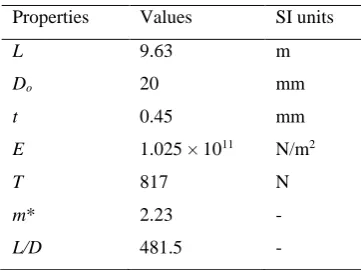
Properties Values SI units
L 9.63 m
Do 20 mm
t 0.45 mm
E 1.025 × 10¹¹ N/m2
T 817 N
m* 2.23 -
L/D 481.5 -
Table 1 Properties of the model riser.
3. Numerical Methods
ANSYS MFX solver is adopted to solve the FSI problem in
this paper.
3.1 Flow Model
The fluid flow around the riser is modelled by solving the
unsteady, incompressible Navier-Stokes equations. The
turbulence flow is simulated using large eddy simulation
(LES) wall-adapted local eddy-viscosity (WALE) model
(Nicoud and Ducros, 1999).
The filtered Navier-Stokes equations are as follows.
i 0
i
u x
i
i j iji j
j i j j i j
u
u p u
u u
t x x x x x x
where τij denotes the subgrid-scale stress. It is defined by
iju u
i j
u u
i j The subgrid-scale stress τij is related to the large-scale strain
rate tensor Sij by Boussinesq approximation:
2
3
ij
ij kk sgsSij 1 2 j i ij j i u u S x x
The eddy-viscosity is computed by
3/ 2 2
5/ 2 5/ 4
d d ij ij
sgs w
d d
ij ij ij ij
S S C
S S S S
where d ij
S denotes the traceless symmetric part of the
square of the velocity gradient tensor:
1
2 2
1 22 3
d
ij ij ji ij kk
S g g
g where 2
ij ik kj
g g g , gij ui/xjand δij is the Kronecker
symbol. The tensor d ij
S can be rewritten in terms of the
[image:2.595.76.257.407.542.2] 1
3
d
ij ik kj ik kj ij mn mn mn mn
S S S
S S where the vorticity tensor is given by
1
2
j i ij
j i
u u
x x
The main advantages of the WALE model are the capability
to reproduce the laminar to turbulent transition and the
design of the model to return the correct wall-asymptotic y+3
(ANSYS Inc., 2013)
The governing equations are discretised using
element-based finite volume method (FVM). Rhie-Chow
interpolation is used for pressure velocity coupling. A
second-order backward Euler scheme is applied for
temporal discretisation and a bounded central difference
[image:3.595.318.523.255.621.2]scheme is adopted for the convective term.
Fig. 2 Mesh at z/L = constant.
Fig. 2 shows the computational mesh in the x-y plane. A
Dirichlet boundary condition is applied to the inlet. A
Neumann boundary condition is imposed on the outlet. A
no-slip boundary condition is used on the cylinder surface
and other surfaces are modelled as symmetry planes where
the velocity normal to the symmetry boundary is zero and
the scalar variable gradients normal to the boundary are also
zero.
3.2 Structural Dynamic Model
The governing equation of a structure’s motion is given by
M
u C
u K
u F where
u is the nodal displacement vector and a dotdenotes differentiation with respect to time. M, C and K
are the mass, damping and stiffness matrices,
respectively.
F is the hydrodynamic force vector. It issolved using the Hilber-Hughes-Taylor (HHT) method
(Chung and Hulbert, 1993) with a second order accuracy.
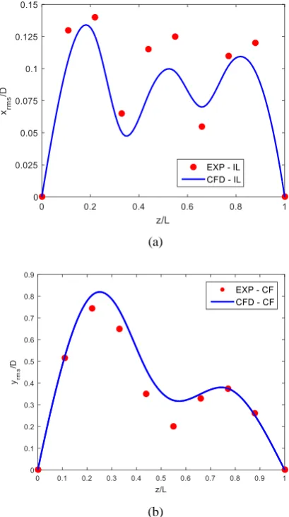
(a)
(b)
Fig. 3 Comparison of CF and IL amplitudes: (a) IL rms amplitude and (b) CF rms amplitude.
4. VIV of a Vertical Riser in Uniform Flow
VIV responses of a vertical riser immersed in uniform
currents are analysed. The current speed is U = 0.42 m/s.
[image:3.595.53.282.400.524.2]Fig. 3 shows the comparison of the in-line (IL) and
cross-flow (CF) amplitudes. The CFD results are in good
agreement with the experimental results. The predicted IL
and CF root mean square (rms) amplitudes are xrms/D = 0.13
and yrms/D = 0.8, respectively.
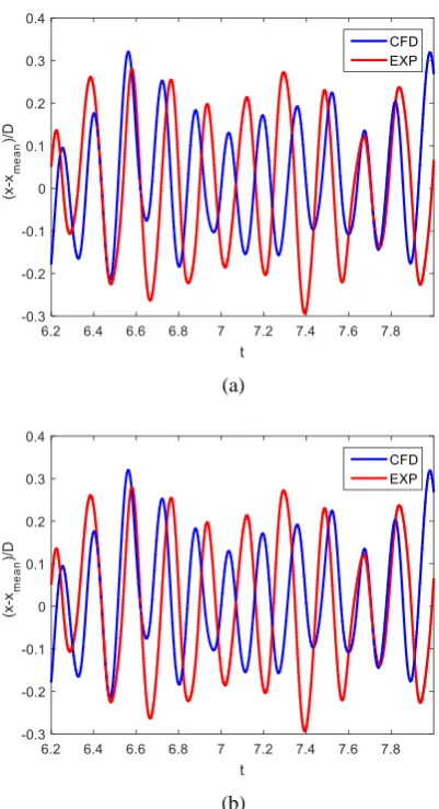
(a)
[image:4.595.60.261.180.550.2](b)
Fig. 4 Time history of displacements (a) IL and (b) CF.
The time history of IL and CF displacements at z/L = 0.22
is compared to the experimental results in Fig. 4. The
predicted amplitudes and frequencies agree with those
obtained in the experiment.
The combined in-line and transverse vibrations of a single
cylinder typically present a figure-of-eight motion as the
dominant frequency in the drag fluctuation is twice of that
in the lift (Prasanth and Mittal, 2009). A figure-of-eight
trajectory is also observed in the present simulation, but
different from the highly repeatable figure-of-eight shapes
obtained from low Reynolds number laminar flow
simulations, the trajectory in the present simulation exhibits
a nonrepeatable feature. Dahl et al. (2010) attributed this
nonrepeatability at subcritical Reynolds numbers to the
irregular in-line motion. Nevertheless, the orbital
trajectories predicted by the current CFD simulation are in
accordance with those in the experiment. An example of
orbital trajectory at z/L = 0.22 is given in Fig. 5. The path
direction of the cylinder motion at z/L = 0.22 appears to have
a clockwise trajectory which illustrates the direction of the
cylinder’s motion at the top position of the figure-of-eight
path. According to the previous study by Bourguet et al.
(2011), clockwise orbits are associated with damping fluid
forces.
(a) (b)
Fig. 5 Orbital trajectory at z/L = 0.22: (a) CFD and (b) EXP.
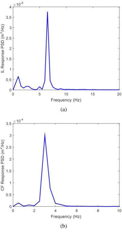
The oscillation frequencies of the cylinder at z/L = 0.22
predicted by CFD is given in Fig. 6. The power spectral
density (PSD) of IL and CF responses are plotted against the
frequency. From the PSD plots, the IL oscillation frequency
is fox= 6.484 Hz and the CF oscillation frequency is foy =
2.993 Hz. The ratio of IL to CF oscillation frequency is
around 2 which verifies the occurrence of dual resonance.
Fig. 7 presents the z-vorticity at different sections of the
riser when t = 8 s. 2P mode is observed at z/L = 0.3 where
[image:4.595.323.503.332.524.2](a)
[image:5.595.62.263.95.479.2](b)
Fig. 6 Response PSD: (a) IL and (b) CF.
5. Conclusions
VIV response of a riser was studied using 3D LES.
Simulation results of uniform flow with U = 0.42 m/s were
presented. The CFD results are in good agreement with the
published experimental data which shows that the present
3D CFD method is capable of predicting VIV of long risers.
The following conclusions can be reached.
The displacement along the riser agree with experimental
data in both the IL and CF directions. When the riser model
is exposed to a flow with free-stream velocity U = 0.42 m/s,
the riser vibrate in the 3rd and the 2nd modes in the IL and
CF directions, respectively. The IL rms amplitude is xrms/D
= 0.13 and the CF rms amplitude is yrms/D = 0.8.
The motion trajectory of the riser is of a figure-of-eight
shape and the ratio of the IL to CF oscillation frequency is
around 2. Both results indicate the occurrence of dual
resonance.
Fig. 7 Z-vorticity along the span at t = 8 s.
2P vortex shedding mode is observed at the location
corresponds to the largest transverse amplitude. 2S mode is
observed elsewhere along the riser.
Acknowledgement
Results are obtained using the EPSRC funded
ARCHIE-WeSt High Performance Computer
(www.archie-west.ac.uk). EPSRC grant no. EP/K000586/1. The authors are also grateful to the “Faculty Engineering Technology Studentship” jointly funded by the Faculty of Engineering
and the Department of Naval Architecture, Ocean and
Marine Engineering.
References
ANSYS Inc., 2013. ANSYS CFX-Solver Theory Guid, Canonsburg, USA.
Bearman, P.W., 1984. Vortex shedding from oscillating bluff body. Annu. Rev. Fluid Mech. 16, 195-222.
[image:5.595.360.494.158.360.2]Bourguet, R., Modarres-Sadeghi, Y., Karniadakis, G.E., Triantafyllou, M.S., 2011. Wake-body resonance of long flexible structures is dominated by counterclockwise orbits. Phys. Rev. Lett. 107.134502, 1-4.
Chaplin, J.R., Bearman, P.W., Huera Huarte, F.J., Pattenden, R.J., 2005. Laboratory measurement of vortex-induced vibrations of a vertical tension riser in a stepped current. J. Fluids Struct. 21, 3-24.
Chung, J., Hulbert, G.M., 1993. A time integration algorithm for structural dynamics with improved numerical dissipation: the generalised - α method. J. Appl. Mech. 60, 371-375.
Constantinides, H., Oakley, O.H., 2008a. Assessment of emprical VIV analysis tools and benchmark with experiments, OMAE2008-57216, Proc. 27th OMAE Conf., Estoril, Portugal.
Constantinides, Y., Oakley, O.H., 2008b. Numerical prediction of VIV and comparison with field experiments, OMAE2008-57215, Proc. 27th OMAE Conf., Estoril, Portugal.
Dahl, J.M., Hover, F.S., Triantafyllou, M.S., Oakley, O.H., 2010. Dual resonance in vortex-induced vibrations at subcritical Reynolds numbers. J. Fluid Mech. 643, 395-424.
Gabbai, R.D., Benaroya, H., 2005. An overview of modelling and experiments of vortex-induced vibrations of circular cylinders. J. Sound Vib. 282, 575-616.
Gu, J., Vitola, M., Coelho, J., Pinto, W., Duan, M., Levi, C., 2013. An experimental investigation by towing tank on VIV of a long flexible cylinder for deepwater riser application. J. Mar. Sci. Technol. 18, 358-369.
Holmes, S., Oakley, O.H., Constantinides, H., 2006. Simulation of riser VIV using fully three dimensional CFD simulations, OMAE2006-92124, Proc. 25th OMAE Conf., Hamburg, Germany.
Huang, K., Chen, H.C., Chen, C.R., 2009. Vertical riser VIV simulation in uniform current. J. Offshore Mech. Arct. Eng. 132, 1-10.
Meneghini, J.R., Saltara, F., Fregonesi, R.A., Yamamoto, C.T., Casaprima, E., Ferrari, J.A., 2004. Numerical simulation of VIV on long flexible cylinders immersed in complex flow fields. Eur. J. Mech. B/Fluids 23, 51-63.
Menter, F., Sharkey, P., Yakubov, S., Kuntz, M., 2006. Overview of fluid-structure coupling in ANSYS-CFX, OMAE2006-92145, Proc. 25th OMAE Conf., Hamburg, Germany.
Nicoud, F., Ducros, F., 1999. Subgrid-scale stress modelling based on the square of the velocity gradient tensor. Flow Turbul. Combust. 62, 183-200.
Prasanth, T.K., Mittal, S., 2009. Vortex-induced vibration of two circular cylinders at low Reynolds number. J. Fluids Struct. 25, 731-741.
Sarpkaya, T., 1979. Vortex-induced oscillations. J. Appl. Mech. 46 (241-258).
Tognarelli, M.A., Slocum, S.T., Frank, W.R., Campbell, R.B., 2004. VIV response of a long flexible cylinder in uniform and linearly sheared currents, OTC 16338, Proc. 2004 Offshore Tech. Conf., Houston, Texas, USA.
Tognarelli, M.A., Taggart, S., Campbell, M., 2008. Actual VIV fatigue response of full scale drilling risers: with and without suppression devices, OMAE2008-57046, Proc. 27th OMAE Conf., Estoril, Portugal.
Trim, A.D., Braaten, H., Lie, H., Tognarelli, M.A., 2005. Experimental investigation of vortex-induced vibration of long marine risers. J. Fluids Struct. 21, 335-361.
Vandiver, J.K., Swithenbank, S., Jaiswal, V., Marcollo, H., 2006. The effectiveness of helical strakes in the suppression of high-mode-number VIV, OTC 18276, Proc. 2006 Offshore Tech. Conf., Houston, Texas, USA.
Willden, R.H.J., Graham, J.M.R., 2001. Numerical prediction of VIV on long flexible circular cylinders. J. Fluids Struct. 15, 659-669.
Williamson, C.H.K., Govardhan, R., 2004. Vortex-induced vibrations. Annu. Rev. Fluid Mech. 36, 413-455.