NUMERICAL OPTIMISATION OF PIEZOCOMPOSITE
MATERIAL PROPERTIES USING 3D FINITE-ELEMENT
MODELLING
Jerzy Dziewierz, Anthony Gachagan, Richard L O'Leary
and Sivaram Nishal Ramadas
University of Strathclyde, 204 George Street, G1 1XW Glasgow, Scotland, UK
e-mail: [email protected]; [email protected]; [email protected]; [email protected]
1-3 connectivity piezoelectric ceramic composite materials are commonly used as the active layer of ultrasonic transducer arrays in many applications. In a typical design, the designer has a freedom to choose between various piezoceramic crystals and polymer fillers that constitute the piezocomposite structure. However, there are many design constraints to be met, including the requirements for uni-modality and low lateral coupling of this periodic material configuration. Additionally, recent developments in material science opened the possibility to adjust the polymer composition, and therefore its parameters, in a continuous manner. Given such a complex design problem, it is convenient to use numerical optimisation to meet the design constraints while maximizing performance. However, classic 1D transducer models, while quick to compute and suitable for optimisation, become inaccurate with these new polymer materials, as they require the use of simplifying assumptions.
In this work, a comprehensive time-domain 3D Finite-Element Model is presented which was designed for efficient computation, making it suitable for use with numerical optimisation. The model takes into account numerous phenomena that could not be modelled in 1D, such as non-uniform surface vibration, and inter-element crosstalk. Additionally, it permits optimisation of the filler polymer composition to maximize performance for the desired application. Results of the optimiser for an example 2.5MHz array design problem are presented and discussed.
1. Introduction
piezoelectric material for many applications, especially in the biomedical and sonar fields. Design of these piezocomposite materials, as in any other engineering field, presents the designer with a series of compromises to be made. Mathematical transducer modelling is a standard tool utilised to determine the transducer parameters and predict system performance. The classic method for modelling behaviour of piezocomposite material is to use a set of equivalent material properties obtained by combining properties of polymer and piezoceramic materials using simplifying assumptions1. Then, a complete transducer design, including matching and backing layers, may be simulated using a reduced-dimension model2.
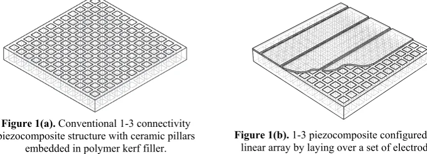
However, when considering the application of the 1-3 piezocomposite material in a linear array arrangement, as illustrated in Fig. 1(b), 1D models cannot take into account the complex physical phenomena associated with the operation of a real array transducer, as they assume many simplifications. There have been attempts to create simple 2D/3D linear systems models that take lateral interactions into account5, but their validity is again restricted. Hence, with modern computing capabilities, it is convenient to utilise Finite-Element (FE) models which provide a more detailed insight into the behaviour of the device3, 4, 6, 7. Importantly, a balance must be achieved between the level of detail in the FE model and the associated computational overhead.
Figure 1(a). Conventional 1-3 connectivity piezocomposite structure with ceramic pillars
embedded in polymer kerf filler.
Figure 1(b). 1-3 piezocomposite configured as a linear array by laying over a set of electrodes.
In this work, a model is proposed that tries to achieve this balance, and allow for extensive, multi-objective numerical optimisation of the array transducer behaviour in realistic time. The objectives for the design of the model included the following:
• Modes of vibration of the piezocomposite structure itself, including the desired fundamental thickness resonances and parasitic lateral modes4, 6
• Dilatation quality of the transducer surface, which takes into account possible anti-phase behaviour of the polymer phase and it’s detrimental effect on the overall acoustic performance of the transducer3, 6
• Mechanical crosstalk between array elements, which must be minimised to ensure good directional performance from the linear array structure6-8
This paper is organized as follows: first, the complexity of the composite design process is discussed. Then, the methodology of the modelling approach is described, followed by a discussion of the optimiser results for the design of a 2.5MHz array transducer device.
2. Design of a Piezoelectric composite for application in ultrasonic
transducer array
[image:2.595.81.513.296.452.2] [image:2.595.336.520.296.418.2]linear array element is determined by the half-lambda design rule and that an integral number of pillars must constitute a single array element. These assumptions directly influence a number of geometric design parameters.
When changing the ceramic volume fraction or polymer composition, the effective longitudinal and shear wave speeds travelling through the composite structure also change1. Therefore, the thickness of the active layer must be adjusted to compensate for any changes in these parameters to match the desired frequency of operation. It is important to note that this is not the only interaction between these parameters.
Gain-Bandwidth Product (GBP) is a nonlinear function of the ratio of piezoelectric composite acoustic impedance to load material acoustic impedance. The acoustic impedance of the composite depends on ceramic volume fraction and polymer properties in a piezoelectric composite structure1. The higher the impedance mismatch between device and load results in a reduction in terms of device bandwidth and sensitivity, as less energy can be transferred between the device and the load. However, when lowering the ceramic volume fraction to improve impedance matching, the volume of active piezoceramic also reduces which impacts on the electro-mechanical efficiency. The softer the polymer used, the easier it is for the ceramic to expand, because the polymer absorbs lateral contraction of the ceramic pillars as they elongate. However, softer polymer materials have a corresponding higher longitudinal wave damping, which also limits GBP. Additionally, with very soft polymers and high ceramic volume fractions, the polymer surface tends to vibrate in anti-phase, being pushed out by the mechanically stiff ceramic3. Similar effects may occur at very low ceramic volume fractions, when the polymer does not bond well to the ceramic pillars and tends to vibrate independently. Accordingly, these effects reduce GBP and may give rise to parasitic surface Lamb waves. Therefore stiffer polymers have to be used at extreme ceramic volume fractions. The impact of material thickness is more straightforward: the thicker the device, the greater the volume of piezoceramic which results in a device with enhanced sensitivity. However, thickness cannot be changed freely because the operational resonant frequency defines the material thickness.
All three parameters have a complex influence on mechanical crosstalk. Softer polymer materials exhibit higher shear wave damping, and hence will result in lower mechanical crosstalk; however, longitudinal wave damping also rises and effectively reduces GBP. Moreover, at certain thickness - wave speed combinations, lamb wave modes of the periodic 1-3 connectivity piezocomposite configuration may come close to the operational frequency of the device. This would cause a significant increase in mechanical crosstalk and is in fact observed in the simulated results found in this work. However, careful design can lead to particular ceramic volume fractions which may not be affected by this phenomenon because their periodic structure creates a stop band filter for these lamb wave modes6.
Given all these dependencies, it is clear that a global optimisation of design parameters using an accurate modelling strategy would enhance understanding of the design process. For this work, a 3D FE model of a piezocomposite array structure has been used to predict important ultrasonic material parameters, GBP and mechanical cross-talk, which are collated and evaluated in an optimiser coded in MATLAB® (The MathWorks, Inc).
3. Methodology
with the other half always in receive mode (connected to a 50Ω load resistor). This approach will provide an estimate of mechanical crosstalk between array elements. However, the crosstalk values returned from this model are not directly comparable to real-world values, because in this symmetrical model every other element in an infinite array is simultaneously excited. Importantly, this assumption does not prevent from optimising the design towards low crosstalk.
The array elements are mechanically interfaced with the load medium as illustrated in Fig. 2(b). The load medium for this work is perspex, as this is a typical NDE angled wedge material, and extends for 3 wavelengths to facilitate near-field wave interaction. The top face of the load medium is terminated by an absorbing boundary to prevent energy reflecting from this surface back to the active piezocomposite layer.
Figure 2(a). Top-down ("thickness plane") view of the 1-3 piezocomposite structure in which the box identifies the actual structure modelled in FE. Dot-dash line – array element boundary; thick line – FE model boundary; dotted line – virtual ceramic material
boundary; thin line – modelled ceramic material boundary
Figure 2(b). Isometric view of the 3D FE model(not to scale). a) acoustic load layer; b) polymer phase; c) ceramic pillar - half; d) ceramic pillar – quarter.
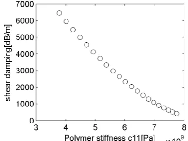
It should be noted that as stated in Section 2, the size of the array element width is fixed to be half-wavelength in perspex at the transducer operating frequency. Moreover, to reduce the computational demand, and simplify the optimisation process, all piezocomposite designs incorporate PZ29 piezoceramic (Ferroperm Piezoceramics A/S, Denmark) as this is considered the industry standard. In addition, new polymeric materials developed at the University of Strathclyde for implementation in piezocomposite array configurations8 have been incorporated into the design process to provide a range of polymer properties relating polymer stiffness to the longitudinal and shear damping as illustrated in Fig. 3(a) and Fig. 3(b).
Figure 3(a). Damping characteristics of polymer range used.
[image:4.595.70.288.216.320.2] [image:4.595.363.481.225.342.2] [image:4.595.69.275.563.713.2] [image:4.595.301.495.564.709.2]The simulation run comprises of three phases: Transmit Phase, Receive Phase and Post-Processing. In the Transmit Phase, one of the simulated array elements is set up in a transmit mode, and excited by wideband electrical pulse. The adjacent element is set up in receive mode. The pressure history is recorded at the absorbing boundary of the load medium for use in the next phase of the simulation. Additionally, the displacement of the surface of the piezocomposite is recorded to provide an estimate of the mechanical crosstalk between excited and neighbouring elements.
In the Receive Phase, both modelled array elements are switched into receive mode, and their electrodes connected to a load resistor (50Ω). The pressure history acquired during the Transmit Phase is used to simulate a returning echo/signal from a reflector located at the top boundary of the load medium. The voltage output from the receiving array elements is recorded.
In the Post-Processing phase, two figures of merit are calculated: Gain-Bandwidth Product of the pulse-echo predict signal and the RMS value of mechanical crosstalk (in dB) between the array elements when operating in transmit mode. These results, and the corresponding waveforms, are saved in a zip file for further analysis. In this work, GBP was calculated only for the frequency range between 2.0MHz to 3.0MHz to promote devices operating with desired centre frequency of 2.5MHz.
It takes less than 15 minutes to run a test case using this FE model for a set of design parameters on a 1GB RAM, dual-AMD Opteron™ 246 Processor PC . At first, running a classic optimisation of the parameters was considered; however, as each case takes considerable time to calculate, and the MATLAB optimisation toolbox does not support restarting an aborted process; therefore, a decision on performing a full-scale brute-force search was made. 3995 test cases have been generated to cover a full range of thicknesses, ceramic volume fractions and polymer stiffness combinations. Specific combinations have been selected to be realistic and realisable using conventional manufacturing techniques. Multiple computers, working in parallel, have been used to speed up the calculation process in following manner: a parameter set for each test case has been written to a numbered file, accessible from a shared location in the local network; then, each computer participating in calculations picks a file containing a test case description, runs three phases of the calculations, stores the results into a zip file, and returns it to a shared location; finally, a single node reads the zipped files and collects all the results for analysis. This method allows for massive parallelisation of the computations. As the FE model results are cached in the last stage, any optimisation algorithm may be used to search inside the pre-calculated result set. Test cases were processed in a randomized order to enable early preview of the results.
4. Discussion of results
Fig. 4 depicts the relationship between GBP and mechanical crosstalk for selected test cases (note - results with GBP lower than 8000 were considered unsuitable for implementation). It is desirable for any transducer array to have good sensitivity and low crosstalk. A range of results in the upper-left corner (i.e. shaded box) of the plot can be interpreted as satisfying this requirement. It is clear that there is a compromise to be considered, as it is possible to select either a case with excellent GBP, or with very low crosstalk, or a blend of two. From Fig. 4 it is also apparent that higher mechanical-crosstalk results in a lowering of the GBP. It is hypothesised that this is because a fraction of the mechanical energy generated by active element is absorbed by the neighbouring (passive) element, and is effectively damped instead of being transmitted into load.
Fig. 4 demonstrates that it is indeed viable to conduct numerical optimisation of the piezocomposite array transducer design using a 3D FE modelling approach. From these results it is possible to identify a region of optimal solutions that minimizes crosstalk and maximizes GBP.
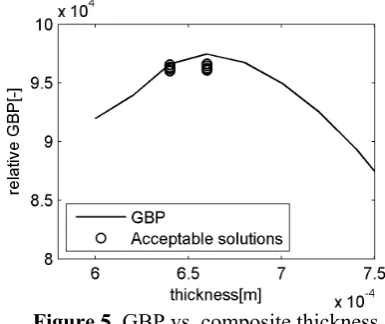
Figure 4. GBP vs. crosstalk for all test cases. Figure 5. GBP vs. composite thickness. The relationship between GBP and piezocomposite thickness, polymer stiffness and CVF are presented in Fig. 5, 6 and 7 respectively. The continuous line in these figures depicts the best possible GBP at given parameter, and small circles indicate the solutions for cases identified from Fig. 4 as potential design solutions (i.e. located within the shaded box). It is important to note that the GBP calculation was weighted to promote devices that are most effective around the desired 2.5MHz centre frequency. The results shown in Fig. 5 predict that there are two piezocomposite thicknesses from the acceptable solutions that produce a high GBP value. In fact, it can be concluded that there are acceptable results for devices in the thickness range of 0.64mm to 0.68mm. This shows that although there may be a specific thickness that gives ideal centre frequency, a thicker device will comprise more active piezoceramic material and produce a stronger electric field, even if the piezocomposite is not resonant at the frequency of interest.
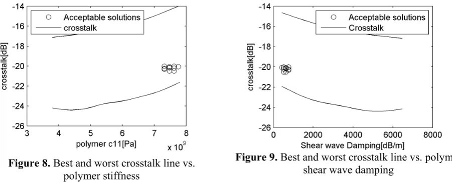
Figure 6. GBP vs. polymer stiffness. Figure 7. GBP vs. Ceramic volume fraction The dependence of GBP on polymer stiffness is shown in Fig. 6 and there is a general trend for the GBP to increase with an increase in polymer stiffness. However, mechanical crosstalk tends to increase as well and this is illustrated in Fig. 8. The basis for this behaviour can be explained by examining the variation of polymer stiffness with both longitudinal and shear damping properties, as illustrated in Fig. 3(b). Increased polymer stiffness will produce a polymer material with significantly reduced shear damping which will promote the propagation of mechanical cross-talk between array elements. Moreover, the acceptable results values are more spread out in the GBP versus CVF relationship as illustrated in Fig. 7, when compared to the results for thickness and polymer stiffness in Fig. 5 and 6. This indicates that, given the pareto line of GBP/crosstalk as illustrated in Fig. 4, CVF may be a function of thickness and/or polymer stiffness.
between mechanical cross-talk in array structures and the polymer stiffness and shear wave damping, respectively. From the acceptable solutions depicted in these Figures it can be determined that the ideal formulation of polymer, in terms of reduced mechanical cross-talk, would comprise high stiffness with a shear damping value towards the lower end of this data set.
[image:7.595.68.519.127.309.2]Figure 8. Best and worst crosstalk line vs. polymer stiffness
Figure 9. Best and worst crosstalk line vs. polymer shear wave damping
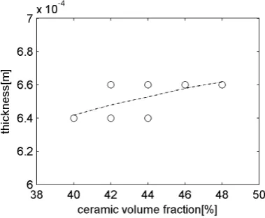
Finally, to investigate the distributed nature of the GBP versus CVF, as shown in Fig. 7, the modelled results have been utilised to determine the interdependence between CVF and the two other design variables in this study: polymer stiffness (Fig. 10) and piezocomposite thickness (Fig. 11). The relationship between CVF and polymer stiffness is again fairly distributed and indicates that there are other significant parameters involved in determining these predictions. Interestingly, a simple relationship between CVF and device thickness can also be extracted. However, it should be noted that this is a relatively small dataset and it is not certain if such relationship will remain valid for all piezocomposite array designs.
5. Conclusions
A distributed computing environment has been used to perform a brute-force search on several design parameters associated with 1-3 connectivity piezoelectric ceramic composite array structures commonly used for ultrasonic transducer array devices. The key design parameters selected for this optimisation process were material thickness, ceramic volume fraction and polymer stiffness. A 3D Finite-Element modelling approach was used to predict array transducer performance indicators: Gain-Bandwidth Product in pulse-echo operation; and inter-element crosstalk. Notwithstanding the considerable amount of data produced from this process, this optimisation approach has shown that it is viable to conduct such a search to aid the design process associated with ultrasonic array transducers. Importantly, it has been demonstrated that an excessive amount of inter-element crosstalk may, apart from its inherent undesirability, lead to reduction of effective gain-bandwidth product of the design.
Figure 10. Polymer stiffness vs. CVF for selected near-optimal set of results.
Figure 11. Composite thickness vs. CVF for selected near-optimal set of results.
Table 1. Final piezocomposite design parameters for a 2.5MHz array
Piezoceramic Polymer Stiffness CVF Thickness
PZ29 7.75GPa 44% 0.66mm
References
1 W. A. Smith and B. A. Auld, Modeling 1-3 composite piezoelectrics: thickness-mode oscillations, Ultrasonics, Ferroelectrics and Frequency Control, IEEE Transactions on, 1991. 2 G.Hayward and J.Hossack, Unidimensional modelling of 1-3 composite transducers, Journal
of the Acoustical Society of America, 1990.
3 G. Hayward and B. J., Assesing the influence of pillar aspect ratio on the behavior of 1-3 connectivity composite transducers, Ultrasonics, Ferroelectrics and Frequency Control, IEEE Transactions on, 1996.
4 J. A. Hossack and G. Hayward, Finite-element analysis of 1-3 composite transducers, Ultrasonics, Ferroelectrics and Frequency Control, IEEE Transactions on, 1991.
5 G. Hayward, D. Gillies and T. S. Durrani, A Multidimensional Linear Systems Model of the Piezoelectric Transducer, IEEE Ultrasonics Symposium, 1984.
6 D. Robertson, G. Hayward, A. Gachagan and V. Murray, Comparison of the frequency and physical nature of the lowest order parasitic mode in single crystal and ceramic 2-2 and 1-3 piezoelectric composite transducers, Ultrasonics, Ferroelectrics and Frequency Control, IEEE Transactions on, 2006.
7 G. Hayward and H. J., Determination of Lamb wave dispersion data in lossy anisotropic plates using time domain finite element analysis, Parts 1&2, Ultrasonics, Ferroelectrics and Frequency Control, IEEE Transactions on, 2006.
[image:8.595.314.504.73.229.2]