International Journal of Innovative Technology and Exploring Engineering (IJITEE) ISSN: 2278-3075, Volume-8 Issue-10, August 2019
Abstract: A 2×2 MIMO planar fractal antenna array using Sierpinski gasket along with microstrip feed line has been investigated. Different configurations of antenna array has been studied. The optimized unit element used in array is further modified geometrically by corner rounding and cut in feed to improve its performance including gain. Proposed fractal array antenna resonates at 4.19 GHz and 7.86 GHz lies in C band and simulated using High frequency structure simulator. Such an attempt has been rarely reported in the literature. Simulated reflection coefficient shows that Proposed antenna works in C band frequency range for various applications and results are quite promising
Index Terms: MIMO, Fractal array, Sierpinski Gasket, C Band
I. INTRODUCTION
Fractal concept are used in various engineering and science discipline like mathematics, Geology and physiology etc. Fractal shapes with electrodynamics used for development of printed antenna, which is very effective. Fractal antenna has a valuable contribution in today’s challenging antenna engineering research [1]. Fractalization of antenna can be achieved through various repetitive structure like Koch curve, sierpinski and other deterministic or non-deterministic fractal shapes. Different type of other modified fractal structure discussed for various applications [2][3]. But sometimes after modification fractal shapes are not properly justified because fractal shapes are the structure which repeat itself and provide multiband or wideband performance [4][5]. Multiband fractal antenna has a compact size because of its increased electrical length and it is easy to fabricate. Fractalization has been achieved through mathematically scaling down the dimension of a structure repetitively. So, it is very useful in achieving multiband/multifunctional characteristics [6][7][8]. Now Multipath fading is a major concern in communication. To mitigate multipath fading multi input and multi output (MIMO) concept is very much used. Channel capacity has been enhanced by MIMO without additional bandwidth and power. High data rate is only possible with MIMO. MIMO Fractal array for 5G applications introduced in[9][10].Printed wide slot array consist of three elements in each array and aligned oppositely. Similarly triangular unit element based 4×4 MIMO array for 5G communication reported in [11]. A 8×8
Revised Manuscript Received on August 09, 2019.
Gurmeet Singh,Department of Electronics and communication enginnering, Sant Longowal Institute of Engineering and Technology, Longowal, Sangrur,Punjab, India.
A.P.Singh, Department of Electronics and communication enginnering, Sant Longowal Institute of Engineering and Technology, Longowal, Sangrur,Punjab, India.
MIMO antenna array for sub 6 GHz of 5G and 10 element array for 5G communications is introduced in [12] [13]. In this paper MIMO based configurations of fractal antenna array is discussed for C band applications.
II. IIDESIGNANDSTRUCTURE
The antenna array is designed on a FR4 substrate of thickness 1.58 mm with dielectric constant 4.4 and loss tangent of 0.017, because FR4 has flame resistant properties and good strength [14]. A microstrip feed is used to achieve the matching with the patch antenna. Firstly, triangular microstrip patch antenna is designed using HFSS Simulator. Then basic triangular shape is simply modified by filleted corner as well as feed and circular cut in feed to improve the performance and same is tuned for desired application. Finally, by utilizing the modified antenna elements 1×2 Sierpinski fractal antenna array and 2×2 Sierpinski antenna array with two configurations is developed with better performance in terms of gain. Following are the design steps:
(a) Conventional Triangular patch antenna (CTPA)
All the dimensions of the patch antenna have been calculated from the mathematical expressions [15] as given by equation (1),(2),(3) and (4). From Equation (1), side length of patch antenna is computed by making use of dielectric constant and given frequency. Effective dielectric constant is calculated by using side length from equation (2). Effective side length as well as resonant frequency by making use of side length and effective side length calculated from (3) and (4). Synthesized antenna performance is examined as per intended application. In Table 1, geometric design parameters triangular patch antenna (Fig. 1.) are given.
(a) Computation of side length
(b) The effective dielectric constant of the Triangular microstrip patch antenna
(c) The effective side length of patch (L)
On the Design of 2×2 MIMO Fractal Antenna
Array for C band applications
After designing the triangular patch antenna, it gets modified along its corner and its feed is also modified to enhance S11 and gain of antenna.
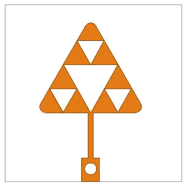
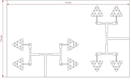
(b) Synthesis of triangular fractal patch antenna array Four different designs of antenna are simulated (1) modified triangular fractal patch antenna (MTFPA) (2) 2×2 modified fractal patch antenna array (3) 2×2 MIMO fractal array with simple configuration (4) 2×2 MIMO fractal array with orthogonal configuration. Sharp bends at corner causes parasitic reactance which change in performnce of antenna. Parasitic reactance is overcome by chamfering and filleting [16]. Then basic patch antenna is modified in the form of filleted corner to reduce parasitic reactance. Reflection coefficient has been improved by cutting slot of circular shape in the feed line. A circular cut is also to get the novelty in shape. These novelties helped to improved performance of basic patch antenna. Modified triangular fractal patch antenna with rounded corner and cut in feed is shown in the Fig. 2. This antenna is transformed into 2×2 fractal array
[image:2.595.67.247.49.232.2]design also filleted for improved performance. 2×2 antenna array with all dimensions (in mm) shown in Fig. 3.
Table I : Design parameters of patch antenna
S. No. Parameters Value (mm)
1 Side Length (a) 19.5
2 Feed width (Wf) 2.8
3 Feed length(Lf) 4
4 Quarter wave Transformer
length (Lqw)
7.7
5 Quarter wave Transformer
width(Wqw)
0.7
6 Ground plane (L×W) 30×30
Lf a
Wqw
Wf Lqw
[image:2.595.318.499.86.266.2]Fig. 1: Conventional triangular patch antenna
Fig. 2 Modified triangular Fractal patch
Fig. 3: 2×2 Modified Triangular fractal antenna array(All dimensions are in mm|)
[image:2.595.42.281.290.480.2]International Journal of Innovative Technology and Exploring Engineering (IJITEE) ISSN: 2278-3075, Volume-8 Issue-10, August 2019
III. RESULTSANDDISSCUSSION
To check the antenna design performance, it is simulated using finite element based method high frequency structure simulator. Antenna performance is measured in terms of S11, S12, S22, gain and bandwidth. S11 of simple fractal patch shows that antenna resonate at 4.2 GHz covers a bandwidth from 4.19 to 4.25 GHz, whereas conventional antenna resonate at 4.9 GHz shown in Fig. 5. Fractal structure shifts resonance at lower frequency. In second design 2×2 array resonates at 4.19 GHz and 7.87 GHz. 2×2 MIMO antenna array with simple configuration resonates at 4.15 GHz and 7.84 GHz. Similarly 2×2 MIMO antenna array with orthogonal configuration resonates at 4.19 and 7.86 GHz shown in Fig. 6,7,8 respectively. Performance parameters S11, S12, S22, gain and bandwidth discussed in table II.
4.0 4.5 5.0 5.5 6.0 6.5 7.0 7.5 8.0
-16 -14 -12 -10 -8 -6 -4 -2 0
S
1
1
(
d
B
)
Frequency(GHz)
IV. UNITS
4.0 4.5 5.0 5.5 6.0 6.5 7.0 7.5 8.0
-20 -18 -16 -14 -12 -10 -8 -6 -4 -2 0 2
S
1
1
(
d
B
)
Frequency(GHz)
s11 of 2×2 Modified Triangular fractal antenna array
4.0 4.5 5.0 5.5 6.0 6.5 7.0 7.5 8.0
-55 -50 -45 -40 -35 -30 -25 -20 -15 -10 -5 0 5
Frequency(GHz) dB(S(1,1)) dB(S(1,2)) dB(S(2,1)) dB(S(2,2))
4 5 6 7 8
-65 -60 -55 -50 -45 -40 -35 -30 -25 -20 -15 -10 -5 0
Frequency(GHz) dB(S(1,1)) [] dB(S(1,2)) [] dB(S(2,1)) [] dB(S(2,2)) [] Fig.4(b) 2×2 MIMO fractal array with orthogonal configuration
Fig. 5. S11 Comparison of MTFPA and Modified triangular patch antenna
[image:3.595.57.284.52.190.2]Fig. 6. S11 of 2×2 Modified Triangular fractal antenna array
Fig. 7. S parameters of 2×2 MIMO fractal array with simple configuration
[image:3.595.319.519.57.220.2]Table II Results of Different Configurations of Antenna Array
Design Freq. GHz S11 (dB) S12 or S21 (dB) S22 (dB) Bandwidth (MHz) Gain (dB) 2×2Fractal Array 4.19 7.82 -18.08 -14.72
--- --- 120 90 4.16 11 2×2MIMO Fractal Array with Simple Configurat ion 4.15 7.84 -28.36 -14.45 -35.76 -31.72 -28.36 -14.45 140 90 2.56 8.19 2×2MIMO Fractal Array with orthogonal Configurat ion 4.19 7.86 -31.03 -12.52 -37.86 -33.82 -31.03 -12.52 160 80 3.73 7.42
(a) Radiation Pattern
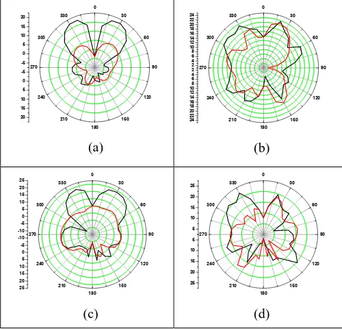
Radiation pattern at ϕ = and ϕ for 4.15 GHz, 7.84 GHz are shown in Fig. 9(a) and 9(b) for first configuration which shows that radiation pattern is distorted at high frequency due to higher order modes. Similarly radiation pattern for orthogonal configuration at 4.19 GHz and 7.86 GHz also shown in Fig. 9(c) and 9(d) respectively.
-5 0 5 10 15 20 0 30 60 90 120 150 180 210 240 270 300 330 -5 0 5 10 15 20 (a) 2 4 6 8 10 12 14 16 18 20 22 24 0 30 60 90 120 150 180 210 240 270 300 330 2 4 6 8 10 12 14 16 18 20 22 24 (b) -10 -5 0 5 10 15 20
25 0 30
60 90 120 150 180 210 240 270 300 330 -10 -5 0 5 10 15 20 25 (c) 5 10 15 20 25 0 30 60 90 120 150 180 210 240 270 300 330 5 10 15 20 25 (d)
V. HELPFULHINTS IV CONCLUSIONS
MIMO Fractal antenna array based on Sierpinski geometry is designed with microstrip feed for wireless C band applications. Proposed antenna array shows dual band
array with simple configuration at lower frequency. Good isolation is achieved in both configurations which proves effectiveness of design.
ACKNOWLEDGMENT
The authors express sincere thanks to the Faculty and Staff of the ECE Department at SLIET, for making laboratory facilities available for present work.
REFERENCES
1. D. H. Werner and S. Ganguly, “An overview of fractal antenna engineering research,” IEEE Antennas Propag. Mag., vol. 45, no. 1, pp. 38–57, 2003.
2. A. Pharwaha, partap Singh, and S. Rani, “A Novel Antenna Design for Telemedicine Applications,” Int. J. Commun. Sci. Eng., vol. 7, no. 12, pp. 617–621, 2013.
3. S. Chaimool, C. Chokchai, and P. Akkaraekthalin, “Multiband loaded fractal loop monopole antenna for USB dongle applications,” Electron. Lett., vol. 48, no. 23, p. 1446, 2012.
4. A. Kulshrestha and B. Khakde, “Fractal Antenna for Multiband Applications,” Int. J. Innov. Eng. Technol., vol. 5, no. 3, pp. 206–214, 2015.
5. A. Awad, S. A. Chahine, Z. Osman, and K. Y. Kabalan, “Investigation of H-tree Multiband Prefractal Antennas,” pp. 1–6, 2020.
6. G. Singh and A. P. Singh, “On the design of planar antenna using Fibonacci word fractal geometry in support of public safety,” Int. J. RF Microw. Comput. Eng., vol. 29, no. 2, p. e21554, Feb. 2019. 7. A. Kumar and A. Partap, “On the Design of 2×2 Element Fractal
Antenna Array using Dragonfly Optimization,” Int. J. Comput. Appl., vol. 179, no. 33, pp. 27–34, Apr. 2018.
8. A. Kumar and A. P. Singh, “Design of micro‐machined modified Sierpinski gasket fractal antenna for satellite communications,” Int. J. RF Microw. Comput. Eng., p. e21786, Apr. 2019.
9. A. A. R. Saad and H. A. Mohamed, “Printed millimeter-wave MIMO-based slot antenna arrays for 5G networks,” AEU - Int. J. Electron. Commun., 2019.
10. P. T. Liu, T. C. Tang, and K. H. Lin, “C-band MIMO antenna with isolation and gain enhancement for MIMO radar applications,” IEEE Antennas Propag. Soc. AP-S Int. Symp., no. 1, pp. 490–491, 2014. 11. D. Thi Thanh Tu, N. Gia Thang, N. Tuan Ngoc, N. Thi Bich Phuong,
and V. Van Yem, “28/38 GHz dual-band MIMO antenna with low mutual coupling using novel round patch EBG cell for 5G applications,” in 2017 International Conference on Advanced Technologies for Communications (ATC), 2017, vol. 2017-Octob, pp. 64–69.
12. M.-Y. Li et al., “Eight-Port Orthogonally Dual-Polarized Antenna Array for 5G Smartphone Applications,” IEEE Trans. Antennas Propag., vol. 64, no. 9, pp. 3820–3830, Sep. 2016.
13. Y. Li, C.-Y.-D. Sim, Y. Luo, and G. Yang, “Multiband 1 -Antenna Array for Sub-6 GHz MIMO Applications in 5-G Smartphones,” IEEE Access, vol. 6, no. May, pp. 28041–28053, 2018.
14. T. P. T. Aguilar JR, Beadle M, “The microwave and RF characteristics of FR4 substrates,” in IEE Colloquium on Low Cost Antenna Technology (Ref. No. 1998/206), pp. 2–6.
15. Nasimuddin, K. Esselle, and A. K. Verma, “Resonance frequency of an equilateral triangular microstrip antenna,” Microw. Opt. Technol. Lett., vol. 47, no. 5, pp. 485–489, Dec. 2005.
16. L. S. Solanki, S. Singh, and D. Singh, “Modified Wideband Bowtie Antenna for WLAN and High Speed Data Communication Applications,” Wirel. Pers. Commun., vol. 95, no. 3, pp. 2649–2663, Aug. 2017.
AUTHORS PROFILE
[image:4.595.41.291.392.632.2]Gurmeet Singh has received his B.Tech degree from Kurukshetra University, Kurukshetra and M.Tech degree from Sant Longowal Institute of Engineering and Technology(SLIET) Punjab. At present, he is pursuing his Ph.D degree in the field of Microstrip Fractal Patch Antennas fromSant Longowal Institute of Engineering and Technology(SLIET) Punjab. His Research interest is in field of antenna engineering research. He has Published three research articles in
International Journal of Innovative Technology and Exploring Engineering (IJITEE) ISSN: 2278-3075, Volume-8 Issue-10, August 2019