International Journal of Innovative Technology and Exploring Engineering (IJITEE) ISSN: 2278-3075,Volume-8 Issue-11, September 2019
Abstract: In bimodular material (different elastic properties in tension and compression) beam, shear-extension, twisting-stretching, bending-twisting coupling are present irrespective of stacking sequence, ply-angle unlike unimodular materials. The presence of these coupling parameters can affect transverse deflection when beam is subjected to pure bending. In this paper an attempt is made to take consideration of these coupling by implementing equivalent stiffness methods along with classical beam theory. The objective is to find out the effects of these couplings on transverse deflections, neutral surface positions and on stress and strain distribution throughout the thickness of the beam. Transverse deflection, neutral surface position, through the thickness stress and strain distribution are obtained for simply supported and clamped-clamped boundary conditions. The analysis shows that results obtained for neutral surface position, positive and negative half cycle frequencies, transverse deflection and even strain, strain distribution through the thickness by considering the coupling parameters are different from the results obatained by neglecting the couplings.
Keywords : Bimodular beam, Laminated composite, Equivalent stiffness, Coupling
I. INTRODUCTION
Few composite materials have nonlinear stress-strain curve (Fig. 1), which can be approximated with two straight lines having different slopes at the origin. These types of materials are called bimodular materials. The examples of such materials are unidirectional boron/epoxy which have compression moduli 15-20% lower than that of the tensile moduli, glass/epoxy composite have 20% lower tensile moduli than compressive moduli, aramid-rubber has tensile moduli 300 times greater than compression moduli and polyester-rubber has tensile moduli 17 times greater than the compressive moduli [1, 2]. It is reported [3] that, due to the material unsymmetry in bimodular material, the coupling parameters never reduced to zero. As a result, the neutral surface does not pass through the geometric mid-plan of the beam even for symmetric laminate [4]. But a wide range of research had been carried out without considering the effects of these coupling parameters in bending, free vibration analysis of bimodular beams/plates. Timoshenko [5] was the first person to analyze flexural stress in isotropic bimodular beam and Kamya [6] analyze transverse shear effect of isotropic bimodular beam. This puzzling phenomenon of different elastic properties in tension and compression
Revised Manuscript Received on September 05, 2019. * Correspondence Author
Nasir Hasan Sk*, Department of Mechanical Engineering, National Institute of Technology Durgapur, India. Email: [email protected]
Amrendra Kumar, Department of Mechanical Engineering, National Institute of Technology Durgapur, India. Email: [email protected]
Kallol Khan, Department of Mechanical Engineering, National Institute of Technology Durgapur, India. Email: [email protected]
especially occur due to microshear crimping and fiber curvature [7]. The different properties in tension and compression makes the assignment of the material properties is a function of strain/stress. So, material models used in bimodular material are different than the material model used in unimodular material. Jones [8], Papazouglou [9] give compliance matrix based bimodular model for two dimensional and three-dimensional stress states. The present paper deals with Bert’s [10] constitutive material model based on stiffness matrix rather than compliance matrix. Tran [4] shows that under axial load alone or under complicated loads the position of the neutral surface changes drastically along the length of the beam in shear deformation theory. Iwase [11] carried out the similar analysis in three different beam theories and found that the position neutral surface varies along axial direction even for transverse load in Levinson beam theory.
In the previous works on bimodular materials [1-11], no author has considered the effects of coupling. In this paper the main objectives are to find out the magnitude of coupling and successfully incorporate in bending analysis of thin laminated bimodular beam. Also, results obtained by conventional stiffness method are compared with equivalent stiffness methods.
II. METHODOLOGY
For thin beam:
Axial displacement:
(1)
Application of Equivalent Stiffness to Consider
Coupling Effects in Bimodular Beam
[image:1.595.315.533.377.536.2]Nasir Hasan Sk, Amrendra kumar, Kallol Khan
Fig. 1. Stress-strain curve of bimodular material Tensile modulus (Et)
Compression modulus (Ec)
Strain (εxx) Stress (σxx)
Actual behavior
Transverse displacement:
(2) Normal strain:
(3) Normal Stress:
(4)
Where, axial displacement of the mid-surface of the beam and is reduced transformed stiffness.
The equations of motion can be obtained from Hamilton’s energy equation.
Hamilton’s Energy equation:
(5)
Where,
First variation of strain energy:
First variation of work done:
First variation of kinetic energy:
Using the expressions of
, and in Hamilton’s energy equation (Eq. 5) we get the following equations of motion.
(6)
(7)
Where the parameters
N
x andM
x are force and momentresultants and
The resultant force (
N
x) and moment (M
x) are defined and calculated as:;
The force and moment resultant can be rewritten in terms of various stiffness parameters (A11: Extensional stiffness,
B11: Bending-stretching coupling stiffness and D11: Bending
stiffness) and primary variables as:
(8)
(9)
Equations of motion in terms of displacements (
):
(10)
(11)
A. Calculations of stiffness parameters: Conventional method (NM) [2]:
Relation between resultant force/moment with strain/curvature shown in Fig. 2.
In case of thin beam
and
. So, only
,
and are useful in equations of motion (Eqs. 10,
11). In this method stiffness parameters (
,
and) are calculated without considering the effects of
,
,
,
,
and ., and are calculated as:
Where Ne is the number of effective layers for
x 11 12 16 11 12 16
y 12 22 26 12 22 26
xy 16 26 66 16 26 66
x 11 12 16 11 12 16
y 12 22 26 12 22 26
xy 16 26 66 16 26 66
N
A
A
A
B
B
B
N
A
A
A
B
B
B
N
A
A
A
B
B
B
M
B
B
B
D
D
D
M
B
B
B
D
D
D
M
B
B
B
D
D
D
2
xx yy xy xx yy xy
Bending-Extension CouplingBending-Extension Coupling Bend-Twist Coupling
[image:2.595.109.498.423.635.2]Shear-Extension Coupling
International Journal of Innovative Technology and Exploring Engineering (IJITEE) ISSN: 2278-3075,Volume-8 Issue-11, September 2019
bimodular composite laminated beam. If any layer is partly under tension and partly under compression then that layer will have partly compressive properties and partly tensile properties and the number of effective layer will be Ne = N+1( N is number of layers in the laminate).
And for kth lamina,
66 2 2 + 22 4
Where θk is ply angle for kth lamina and n has two values
(t and c) if the lamina is under tension then n = t and if the lamina is under compression then n = c is considered.
The reduced stiffness parameters
(
) are calculated as:
; ; ;
Vinson-Sierakowski equivalent stiffness method (VS) [12]:
In this method the stiffness parameters are calculated as:
All the coupling parameters are taken into consideration by equivalent elastic modulus ( ) and put appropriate weightage in , and .
Here,
and
E
11k
,
E
22k ,G
12k ,
12k and
kare Young’s modulus in fiber direction, Young’s modulus transverse to fiber direction, in-plane shear modulus, in-plane poisons ratio and ply angle for kth layer respectively.Rios-Chan equivalent stiffness method (RS) [13]: Rios and Chan [21] calculated equivalent stiffness parameters by inverting [ABD] matrix. The method was originally for unimodular material. So, few changes (assigning material properties in tension and compression) are required for implementing in bimodular materials.
The equivalent stiffness parameters are calculated as:
Where, a11 = J11, b11 = J14, d11 = J44 and [J] = [ABD]-1
Kaw equivalent stiffness method (Kaw) [14]: This method is similar to VS method. The equivalent elastic modulus ( ) is used to calculate equivalent
stiffness parameters. However, Kaw’s equivalent elastic
modulus ( ) is different from VS.
Where, equivalent elastic modulus ( ) for kthlamina
Here, I=bh3/12, d11 = J44 and [J] = [ABD]-1. The [ABD]
matrix is same as calculated in Rios-Chan method (RS) and b, h are the width and thickness of the beam.
B. Neutral surface location
One of the important parts for analysis of bimodular material laminated structures is identifying the neutral surface (εxx= 0) location. In this work iterative technique is
used to locate the neutral surface position. To initiate the iteration, process the geometric mid-plane is assumed as
the neutral surface, material properties
(tensile/compressive) are assigned depending upon the strain distribution. If strain is positive (tensile strain) the tensile properties are assigned and if the strain is negative (compressive strain) the compressive properties are assigned.
The equation of neutral surface can be written as:
;
After each iteration modified zn, [ABD] and strain are
calculated to get the new modified [ABD] matrix. The iteration continues till the desired level of accuracy for zn is
obtained.
C.
Solution methodology
Boundary conditions:
Simply supported (SS):
, at x=
-L/2, L/2The general solution assumed for u0 and w which
satisfies the SS boundary conditions and Eqs. (10) and (11) as:
Where
L
ii
for SS beam and L is the length of thebeam, i is number of terms are to be considered for converged value of displacements.
Clamped-Clamped (CC):
, at x=
-L/2, L/2
The general solution assumed for u0 and w which
where
2
L
i
i
for CC beamFor both the boundary conditions, the origin of the coordinate system is considered at the center of the beam.
The Fourier series expansions of axial force (Px) and
transverse force (Pz) are written as:
Putting the values of
u w
0, , P , P
x z in equations ofmotion (Eqs. 6,7) and solved for the constants
A , C
i i:
Where,
2 4 3
11 11 22 11 21 12 11
C
A , C
D and C
C
B
i i i
Non-dimensional transverse deflection
and
non-dimensional stress (
) are expressed as:
,
Where wmax is maximum displacement and q0 is
intensity of uniformly distributed transverse load.
III. RESULTS AND DISCUSSION
[image:4.595.55.268.52.168.2]Numerical results are obtained to verify the presence of non-zero coupling parameters in thin bimodular beam. Also, non-dimensional transverse deflection, stress and strain distributions are obtained for both conventional stiffness parameters and equivalent stiffness parameters for the materials presented in Table I. The dimensions of the beam are: aspect ratio (L/h) = 20, thickness ratio (b/h) = 0.5.
Table- I: Material Properties [Material 1: Aramid Rubber, Materiel 2: Polyester Rubber]
Materials
Properties in Tension Properties in compression
E11 t
(GPa)
E22 t=E33 t
(GPa)
G12t=G13t
(GPa)
G23t
(GPa) ν12t = ν23t = ν13t (GPa)E11 c
E22 c=
E33 c
(GPa)
G12c=G13c
(GPa)
G23t
(GPa) ν12c=ν23c=ν13c
Material 1 [3] 3.58 0.00909 0.0037 0.0029 0.416 0.012 0.012 0.0037 0.0029 0.205
[image:4.595.47.547.350.450.2]Material 2 [3] 0.617 0.008 0.00262 0.00223 0.475 0.0369 0.0106 0.00267 0.00475 0.185
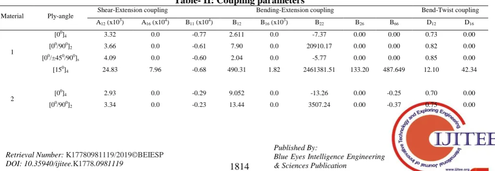
Table II shows coupling parameters of all possible types of stacking sequence in a laminated beam, which are unidirectional laminate [00]4, cross-ply laminate [00/900]2,
mixed ply laminate [00/±450/900]s and angle-ply laminate
[150]4. The observation displayed that bending-extension
coupling (B11) exist for all stacking sequence and
magnitude of this coupling is minimum for cross-ply laminate. A16, B16, B26, B66 and D16 are non-zero only in
case of mixed-ply/angle-ply laminates. One other observation is that bend-twist coupling parameters are significantly small compared to shear-extension and bending-extension coupling. The equivalent stiffness captures all these coupling parameters and put appropriate
weightage into A11, B11 and D11.
The effect of these coupling parameters on A11, B11, and
D11 is presented in Table III. The difference between the
results obtained by conventional stiffness method (NM) and equivalent stiffness methods (VS, RC and Kaw) is negligible for unidirectional laminate [00]4, cross-ply
laminate [00/900]2. But, for angle-ply laminate [150]4 NM
overestimate the stiffness parameters (A11, B11, D11) 5 to
[image:4.595.51.561.658.834.2]10 times except Kaw’s equivalent stiffness method. It is clear from Table II and Table III that coupling is maximum in case of angle-ply laminate and minimum in case of unidirectional laminate.
Table- II: Coupling parameters
Material Ply-angle
Shear-Extension coupling Bending-Extension coupling Bend-Twist coupling
A12 (x103) A16 (x104) B11 (x104) B12 B16 (x103) B22 B26 B66 D12 D16
1
[00]
4 3.32 0.0 -0.77 2.611 0.0 -7.37 0.00 0.00 0.73 0.00
[00/900]
2 3.66 0.0 -0.61 7.90 0.0 20910.17 0.00 0.00 0.82 0.00
[00/±450/900]
s 4.09 0.0 -0.60 2.04 0.0 -5.77 0.00 0.00 0.85 0.00
[150]
4 24.83 7.96 -0.68 490.31 1.82 2461381.51 133.20 487.649 12.10 42.34
2 [0
0]
4 2.93 0.0 -0.29 9.052 0.0 -13.26 0.00 -0.25 0.70 0.00
[00/900]
International Journal of Innovative Technology and Exploring Engineering (IJITEE) ISSN: 2278-3075,Volume-8 Issue-11, September 2019
[00/±450/900]
s 13.52 0.56 -0.21 106.14 0.10 221045.89 100.15 98.43 3.33 2.12
[150]
4 14.49 4.24 -0.25 188.41 0.67 5854507.21 53.53 179.03 4.91 15.59
Table- III: Conventional and equivalent stiffness parameters
Material Ply-angle A11 x (105) B11 x (104) D11 x (105)
NM VS RC Kaw NM VS RC Kaw NM VS RC Kaw
1
[00]
4 3.47 3.44 3.44 3.29 -0.77 -0.76 -0.76 -0.73 181.12 179.83 179.84 173.35
[00/900]
2 2.76 2.71 2.71 2.67 -0.61 -0.60 -0.60 -0.60 147.64 145.44 145.40 143.63
[00/±450/900]
s 2.69 2.48 2.64 2.67 -0.60 -0.55 -0.59 -0.59 144.76 134.45 141.88 143.50
[150]
4 3.10 0.32 0.70 2.47 -0.68 -0.03 -0.008 -0.24 160.72 8.55 14.54 403.288
2
[00]
4 1.90 1.89 1.89 1.89 -0.29 -0.29 -0.29 -0.29 68.58 68.25 68.28 68.28
[00/900]
2 1.29 1.28 1.28 1.23 -0.23 -0.23 -0.23 -0.23 52.82 52.55 52.60 50.91
[00/±450/900]
s 1.21 1.11 1.18 1.21 -0.21 -0.20 -0.20 -0.21 52.88 50.13 51.41 52.80
[150]
4 1.68 0.36 0.44 1.56 -0.25 -0.01 -0.01 -0.24 60.28 7.83 9.46 57.74
In the next section, all these coupling parameters have been considered using equivalent stiffness methods to determine transverse deflection and compared with conventional stiffness method. Table IV and Table V shows the non-dimensional transverse deflection and neutral surface position for SS and CC boundary conditions respectively. It is observed from the tables that for unidirectional laminate and cross-ply laminate conventional stiffness method has almost same result compared with equivalent stiffness methods. But for angle-ply laminate and cross-ply laminate NM method underestimate the magnitude of non-dimensional transverse deflection for both Material 1 and Material 2. The results obtained for simply supported boundary condition has same nature with clamped-clamped
boundary condition. But, magnitude of non-dimensional transverse deflection for clamped-clamped boundary are much smaller than simply supported boundary condition. Interestingly, these two-boundary condition have no effect on the position of the neutral surface. Fig. 3 shows the variation of neutral surface of single layer lamina as ply-angle shifts from 00 to 900for Material 1 and Material 2. It is observed that for all stiffness methods the neutral surface move towards the geometric mid-plane of the beam as the ply-angle advance towards 900. VS and RC methods are more sensitive in the vicinity 00 to 300, after that gradual decrease of neutral surface is observed. Whereas, NM and Kaw’s method overlap with each other and have different trends than VS and RC.
Table- IV: Non-dimensional transverse deflection (w) and neutral surface position (z/h) of Simply supported beam [SS]
Material Ply- angle NM VS RC Kaw
z/h z/h z/h z/h
1
[00]
4 0.444 4.19 0.445 4.371 0.445 4.371 0.444 4.197
[0o/90o] -0.012 17.47 -0.011 17.88 -0.013 17.49 -0.012 17.50
[0o/90o]s 0.444 4.19 0.445 4.37 0.445 4.37 0.444 4.19
[0o/±45o/90o]s 0.445 4.39 0.447 4.73 0.446 4.39 0.445 4.39
[45o/0o/-45o/90o]s 0.397 4.93 0.330 7.15 0.328 6.31 0.397 4.93
[300/45o/-45o/-30o
]s -0.430 4.75 -0.039 15.42 -0.251 5.03 -0.436 6.22
2
[00]
4 0.302 1.723 0.303 1.738 0.303 1.737 0.302 1.723
[0o/90o] -0.079 8.92 -0.079 8.98 -0.079 8.94 -0.078 9.07
[0o/90o]s 0.334 2.15 0.334 2.17 0.334 2.17 0.334 2.15
[0o/±45o/90o]s 0.344 2.54 0.358 2.95 0.343 2.55 0.344 2.54
[45o/0o/-45o/90o]s 0.279 3.42 0.256 4.98 0.246 4.11 0.279 3.42
[300/45o/-45o/-30o
Table- V: Non-dimensional transverse deflection (w ) and neutral surface position (z/h) CC
Material Ply- angle NM VS RC Kaw
z/h z/h z/h z/h
1
[00]
4 0.444 0.839 0.445 0.874 0.445 0.874 0.444 0.839
[0o/90o] -0.012 3.49 -0.0116 3.57 -0.012 3.49 -0.012 3.49
[0o/90o]s 0.444 0.83 0.445 0.87 0.445 0.87 0.444 0.83
[0o/±45o/90o]s 0.445 0.87 0.447 0.94 0.445 0.87 0.445 0.87
[45o/0o/-45o/90o]s 0.397 0.98 0.330 1.43 0.327 1.26 0.397 0.98
[300/45o/-45o/-30o]
s -0.430 0.95 -0.039 3.08 -0.251 1.01 -0.436 1.24
2
[00]
4 0.302 1.723 0.303 1.738 0.303 1.737 0.302 1.723
[0o/90o] -0.079 1.78 -0.079 1.79 -0.079 1.78 -0.079 1.78
[0o/90o]s 0.334 0.43 0.334 0.43 0.334 0.43 0.334 0.43
[0o/±45o/90o]s 0.344 0.50 0.358 0.59 0.342 0.51 0.344 0.50
[45o/0o/-45o/90o]s 0.279 0.68 0.256 0.99 0.246 0.82 0.279 0.68
[300/45o/-45o/-30o]
s -0.300 0.63 -0.006 3.22 -0.179 1.03 -0.304 0.66
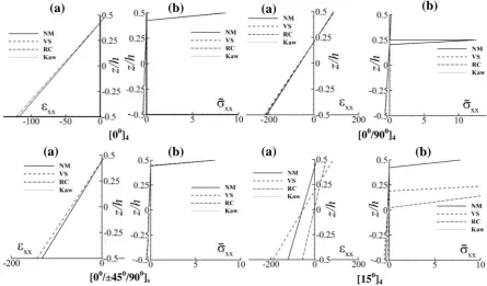
Fig. 4-7 shows the through the thickness strain and through the thickness non-dimensional stress distribution for simply supported [SS] and clamped-clamped [CC] boundary condition for Material 1 and Material 2. In [00]4
and [00/900]4 laminates all the equivalent stiffness and
conventional stiffness method show same strain and stress distribution. But small difference is observed in [00/±450/900]s for both the materials. In case of angle-ply
laminate [150]4 NM and Kaw’s method underestimate both
[image:6.595.42.558.61.261.2]stress and strain than VS method.
Fig 3. Variation of neutral surface with ply-angle ( )
[00]4 [00/900]4
[00/±450/900]s [150]4
Fig. 4. (a) Strain and (b) stress distribution of Material 1 [SS]
(a)
(a)
(b)
(a)
(b)
(a)
(b)
[image:6.595.68.514.464.725.2]International Journal of Innovative Technology and Exploring Engineering (IJITEE) ISSN: 2278-3075,Volume-8 Issue-11, September 2019
Fig. 5. (a) Strain and (b) stress distribution of Material 1 [CC]
[00]4 [00/900]4
[00/±450/900]s [150]4
(a)
(b)
(a)
(b)
(a)
(b)
(a)
(b)
[00/±450/900]s [150]4
2
[00]4 [00/900]4
(a)
(a)
(a)
(a)
(b)
(b)
(b)
(b)
[image:7.595.61.501.94.357.2]IV. CONCLUSIONS
This paper presents that the coupling parameters are non-zero irrespective of stacking sequence of the bimodular beam. These coupling parameters are taken into consideration by using equivalent stiffness method to implement in bending analysis and stress/strain distribution. The following conclusions are drawn from the above discussion
The effect of coupling parameters on transverse deflection, stress and strain distribution is more in case of angle-ply laminate as compared to cross-ply laminates.
The neutral surface obtained by equivalent stiffness methods are different from conventional stiffness method. The neutral surface shifts towards the top fiber for all equivalent stiffness methods as the ply-angle changes from 00 to 900 single layer lamina.
Beam end supports (SS, CC) have significant effect on transverse deflection, but have no effect on position on neutral surface.
ACKNOWLEDGMENT
The authors are thankful to the department of Mechanical Engineering, NIT Durgapur, for their help and support.
REFERENCES
1. R.M. Jones, and H.S. Morgan, “Bending and extension of cross-ply laminates with different moduli in tension and compression”,
Comput. Struct, vol. 11(3), 1980, pp. 181-190.
2. R.M. Jones, “Mechanics of composite materials”, 2nd ed., Tailor & Francis, 1980.
3. C.W. Bert, and C.J. Rebello, “Bending of laminated thick beams of bimodular material”, Eng. Struct., vol. 5(3), 1983, pp. 227-231. 4. A.D. Tran, and C.W. Bert, “Bending of thick beams of bimodulus
materials”, Comput. Struct, vol. 15(6), 1982, pp. 627-642. 5. S. Timoshenko, “Strength of materials, part II, Advanced Theory and
Problems”, 2nd ed., Van Nostrand Company, 1941.
6. N. Kamiya,. “Transverse shear effect in bimodular plate”, Nuclear Engineering and Design, vol. 32, 1975, pp. 351-357.
7. C.W. Bert, “Effect of bimodularity on mechanical properties of planar-random fiber composites”, Compos. Sci.Technol., vol. 26, 1986, pp. 119-128.
8. R.M. Jones, “Stress-strain relations for materials with different moduli in tension and compression” AIAA Journal, 15, 1976, pp. 16-23.
9. J.L. Papazoglou, and N.G. Tsouvalis, “Mechanical behaviour of bimodulus laminated plates”, Compos. Struct., vol. 17, 1991, pp. 1–22.
10. C.W. Bert, “Models for fibrous composites with different properties in tension and compression”, J. Eng. Mater. Technol, 99(4), 1977, pp. 344–349.
11. T. Iwase, and K. Hirashima, “High-accuracy analysis of beams of bimodulus materials”, J. Eng. Mech., vol. 126(2), 2000, pp. 149-156. 12. J.R. Vinson, and R.L. Sierakowski, “The behavior of structures
composed of composite materials:, Springer, 2008.
13. G. Rios, and W.S. Chan, “A unified analysis of stiffener reinforced composite beams”, Ph.D Dissertation, Arlington: University of Texas, 2009.
[00/±450/900]s [15
0] 4
[00]4 [00/900]
4
(a)
(a)
(a)
(a)
(b)
(b)
(b)
(b)
International Journal of Innovative Technology and Exploring Engineering (IJITEE) ISSN: 2278-3075,Volume-8 Issue-11, September 2019
AUTHORSPROFILE
Nasir Hasan Sk completed his Bachelor degree in Mechanical Engineering from Assam Engineering College Guwahati and his Master’s degree from NIT Silchar. He is currently pursuing his Ph.D. in Bimodular Composite Materials in Mechanical Engineering Department of NIT Durgapur.
Amrendra Kumar received his B. Tech. in Mechanical engineering from NIT Jamshedpur, Jharkhand (India) and the M.Tech. from NIT Durgapur, West Bengal (India). He is currently pursuing the Ph.D. in Machine Design (Mechanical engineering Dept.) at the NIT Durgapur of West Bengal (India). His current research involves the field of Composite Material.

![Fig. 2. Relation between resultant force/moment with strain/curvature using [ABD] [2]](https://thumb-us.123doks.com/thumbv2/123dok_us/8177812.253972/2.595.109.498.423.635/fig-relation-resultant-force-moment-strain-curvature-using.webp)
![Fig. 5. (a) Strain and (b) stress distribution of Material 1 [CC]](https://thumb-us.123doks.com/thumbv2/123dok_us/8177812.253972/7.595.61.501.94.357/fig-strain-b-stress-distribution-material-cc.webp)
